International Research Journal of Engineering and Technology (IRJET) e ISSN: 2395 0056

Volume: 09 Issue: 06 | June 2022 www.irjet.net p ISSN: 2395 0072
International Research Journal of Engineering and Technology (IRJET) e ISSN: 2395 0056
Volume: 09 Issue: 06 | June 2022 www.irjet.net p ISSN: 2395 0072
1M Tech student, Power Electronics, Dept. of EEE, Toc H Institute of Science and Technology, Arakkunnam, Kerala, India
2Assistant Professor, Dept. of EEE, Toc H Institute of Science and Technology, Arakkunnam, Kerala, India ***
Abstract Basically, a boost converter a crucial component of a solar network improves the output voltage of renewable energy sources. In this converter, a diode can be swapped out for a MOSFET to increase the efficiency of boost converters. The adoption of MOSFET is anticipated to reduce power loss because its internal resistance is lower than a diode's. In this essay, synchronous and nonsynchronous boost converters are compared. MATLAB Simulation has been used to model a 50W prototype. The performance of the synchronous and non synchronous boost converter topologies was evaluated. Both circuits' efficiency was compared and examined. The results of the simulation analysis show that, for a given input power, the output power of the synchronous boost converter is greater than that of the non synchronous boost converter. As a result, synchronous boost converter efficiency is higher and is attained at 95%, whereas regular boost converter efficiency is only at 90%.
Key Words: Photo voltaic system, Synchronous boost converter, Non Synchronous boost converter.
Renewable energy sources are developing quickly, particularlyphotovoltaic(PV)applications.Thesesystems produce electricity using renewable energy. PV systems produce clean electricity and are more environmentally friendlythanconventionalenergysources.
Modern electronic systems demand resources with excellent efficiency. By switching out the diode for a MOSFET,theDCtoDCconvertercanbemoreeffectiveasa sourceofpowerforelectronicdevices.SynchronousDCto DCconverterreferstotheDCconverterfromDCoperating in MOSFET synchronization mode. The MOSFET and the synchronous converter cannot operate simultaneously andmusthavethesamefrequency Itisenvisagedthatby using MOSFETs, which have low internal resistance in conduction mode, the power loss from DC to DC converterswillbereduced.
The work that is currently being presented compares two topologies. The non synchronous boost converter is
the first. The synchronous boost converter is the second topology.Intheexperiment,theinputandoutputpowerof synchronous and nonsynchronous boost converters will be calculated and compared, and the efficiency will be examined.
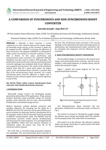
The provided voltage is increased to the desired level using a non synchronous boost converter. Any DC source, whetherasolarpanel,batteries,oranotherdevice,maybe usedastheconverter'sinput.
Figure 1 depicts the circuit diagram for the non synchronizedboostconverter.
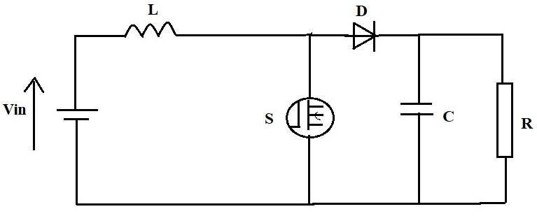
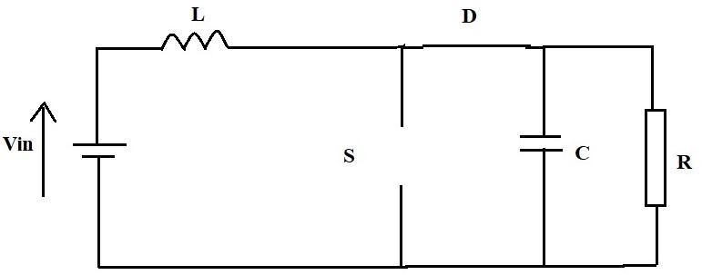
The Nonsynchronous Boost Converter has two alternative architectures in continuous mode, as shown in Fig.2.
The switch S is turned on. Through the supply voltage, theinductorstoresenergyandchargesitself.Theinductor currentprogressivelyrisesunderthesecircumstances.
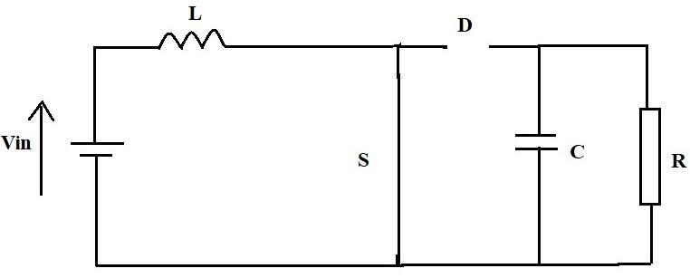
The switch S is in the off state. The inductor's polarity shifts, and energystored there is used to power the diode andchargethecapacitor.
International Research Journal of Engineering and Technology (IRJET) e ISSN: 2395 0056
Volume: 09 Issue: 06 | June 2022 www.irjet.net p ISSN: 2395 0072
L=
where iL is the ripple current and f is the switching frequency
Thevalueofthecapacitoriscreatedusing: C= Where∆Vcistheripplevoltage
(a) (b)
Fig 2: Non synchronousBoostConvertercircuit configurations.(a)On state;(b)Off state
Thedutycycleisdeterminedusingtheformulabelow: D=1 theinputvoltageVin,andtheoutputvoltageVout
ThesourceoftheloadRis: R= wherePin denotesthepowerinput
The following formula is used to determine the input and outputcurrents: Iout = Iin =
Thedesignoftheinductorvalueinvolves:
There is 50 w of input power. The circuit receives a 12 voltinputandoperatesatafrequencyof40kHz.
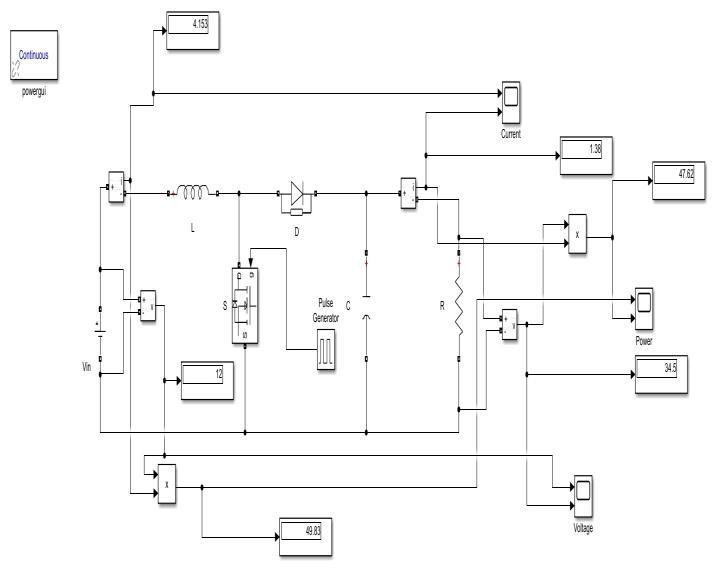
The circuit for the non synchronous boost converter is depicted in Figure 3 and is modelled using MATLAB simulation.
Fig 3: DiagramoftheNon SynchronousBoostConverter SimulationCircuit
International Research Journal of Engineering and Technology (IRJET) e ISSN: 2395 0056
Volume: 09 Issue: 06 | June 2022 www.irjet.net p ISSN: 2395 0072
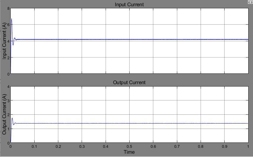
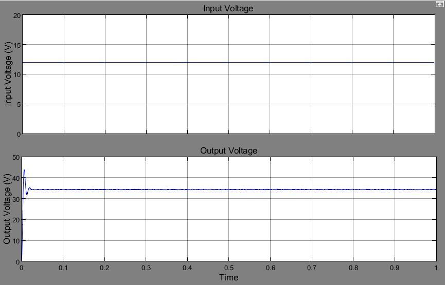
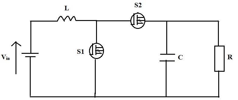
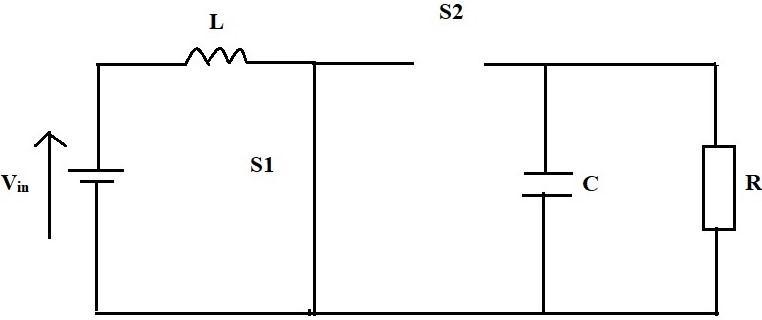
Figure 5 depicts the circuitschematicfor thesynchronous boostconverter.
Incontinuousmode,thesynchronousboostconverterhas twopotentialstructures,asdepictedinfig.6.
Whenever switch S1 is activated. Through the supply voltage, the inductor stores energy and charges itself. The inductor current progressively rises under these circumstances.
WhileS1isoffandS2isswitchedon.Theoutputstage receives the energy that has been inductively stored. The inductor current gradually diminishes under these circumstances.
SwitchS2willbeOFFwhenswitchS1isON,andviceversa. This is how a synchronous boost converter's switches are activated. There is a dead interval between the activation ofthetwoswitchestopreventshotthroughscenarios. (a)
International Research Journal of Engineering and Technology (IRJET) e ISSN: 2395 0056
Volume: 09 Issue: 06 | June 2022 www.irjet.net p ISSN: 2395 0072
Thereis50wofinputpower.Thecircuitreceivesa12volt inputandoperatesatafrequencyof40kHz.
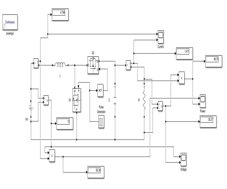
The MATLAB simulation is used to simulate the synchronous boost converter, and Figure 7 depicts the circuit.
(b)
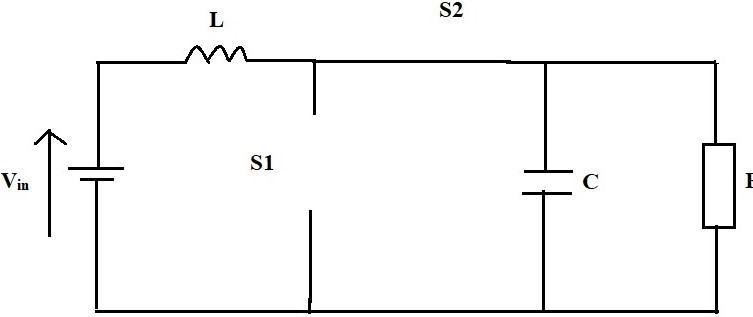
Fig 6: Synchronousboostconvertercircuitconfiguration. (a)S1isturnedonwhileS2isoff.(b)S2isONwhileS1is OFF.
Thedutycycleisdeterminedusingtheformulabelow: D=1 theinputvoltageVin,andtheoutputvoltageVout ThesourceoftheloadRis: R= wherePin denotesthepowerinput
The following formula is used to determine the input and outputcurrents: Iout = Iin = Thedesignoftheinductorvalueinvolves: L= where iL is the ripple current and f is the switching frequency
Thevalueofthecapacitoriscreatedusing: C= Where∆Vc istheripplevoltage
Fig 7: DiagramoftheSynchronousBoostConverter SimulationCircuit
(a)
International Research Journal of Engineering and Technology (IRJET) e ISSN: 2395 0056
Volume: 09 Issue: 06 | June 2022 www.irjet.net p ISSN: 2395 0072
(b)
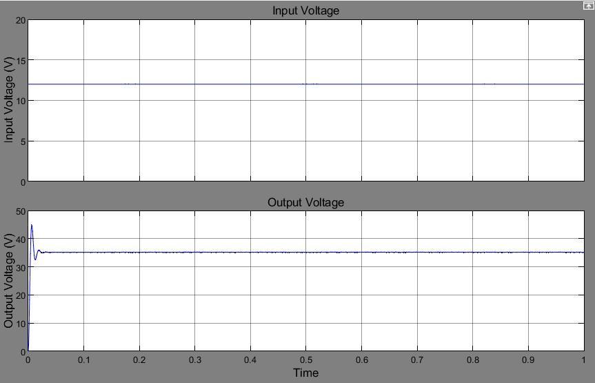
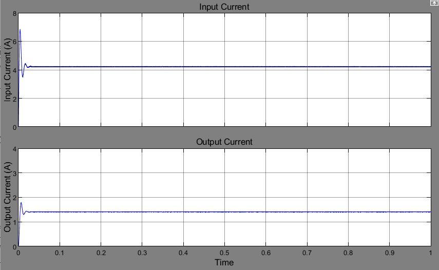
Fig -8: Electricalsignalwaveforms.Asynchronisedboost converter's(a)InputandOutputVoltage(b)Inputand OutputCurrent
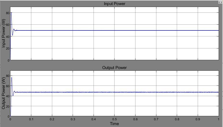
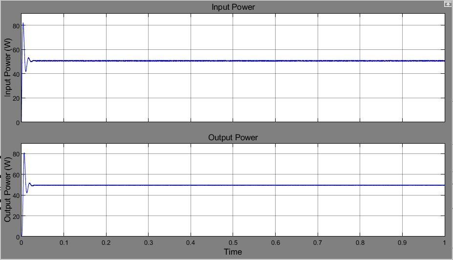
Another important simulation result is the higher efficiency with the use of synchronous boost converters. GraphsinFigs.9and10show,respectively,theinputand output powers of synchronous and non synchronous boost converters. The values of the input output power were calculated through simulation and are shown in TABLEI.
Fig -10: Powerofthesynchronousboostconverter'sinput andoutput
Table 1: Comparingtheefficiencyofsynchronousand non synchronousboostconvertersforthesamesystem parameters
Power Input(W) Power Output(W) Efficiency (%)
Fig -9: Powerofanon synchronousboostconverterat inputandoutput
Non Synchronous Boost Converter
50 49.75
50 47.62 Synchronous Boost Converter
For the same input power, it is discovered that the synchronousboostconverter'soutputpowerishigherthan the non synchronous boost converter As a result, synchronous boost converter efficiency is higher, at 95%, compared to non synchronous boost converter efficiency, whichisonly90%.
In this paper, a comparison of synchronous and asynchronous boost converters is presented. Each topology's entire design was analyzed. The simulation outcomes for these converters are discussed. The output analysis shows that the synchronous boost may increase the voltage even with a low input voltage, in contrast to the other topologies. The synchronous boost converter topology is the best one, according to the efficiency analysis.
International Research Journal of Engineering and Technology (IRJET) e ISSN: 2395 0056 Volume: 09 Issue: 06 | June 2022 www.irjet.net p ISSN: 2395 0072
[1] Sibi Philip, Preetha P.K, Vinod Kumar Gopal. “DC Link Voltage Regulation of a Battery Integrated Solar Photo Voltaic System.” 3rd IEEE International Conference on Recent Trends in Electronics, Information & CommunicationTechnology(RTEICT2018)
[2]AnushaVadde,SachinS.,V.S.N.SitaramGuptaV.“Real Implementation of Synchronous Boost Converter with Controller for Power Factor Correction.” 978 1 5090 6255 3/17/$31.00©2017IEEE.
[3] Nesrine Boujelben, Ferdaous Masmoudi, Mohamed Djemel and Nabil Derbel. “Design and Comparison of Quadratic Boost and Double Cascade Boost Converters with Boost Converter.” 2017 14th International MultiConferenceonSystems,Signals&Devices(SSD)
[4] Zhang M.T, Jovanovic M.M , Lee F.C.Y , 1998, “Design Considerations and Performance Evaluations of Synchronous Rectification in Flyback Converters”, IEEE TransactionsonPowerElectronics,vol.13No.3,pp.538 546
[5] Mirza Mursalin Iqbal, Kafiul Islam, “Design And Simulation of A PV System With Battery Storage Using Bidirectional DCDC Converter Using Matlab Simulink”, International journal of scientific & technology research volume6,issue07,july2017