International Research Journal of Engineering and Technology (IRJET)

e-ISSN: 2395-0056
Volume: 09 Issue: 06 | June 2022 www.irjet.net p-ISSN: 2395-0072
e-ISSN: 2395-0056
Volume: 09 Issue: 06 | June 2022 www.irjet.net p-ISSN: 2395-0072
Sanjan P S1 , Dr. Madhu B R2
1Department of Electrical and Electronics, RV College of Engineering, Bangalore, India
2Assistant Professor, Department of Electrical and Electronics, RV College of Engineering, Bangalore, India
Abstract Inthispaper,acomparativeanalysisiscarried out on the performance of a Field Oriented Controlled (FOC) based speed and position control of BLDC motor using Sinusoidal Pulse Width Modulation (SPWM) and Space Vector Pulse Width Modulation (SVPWM) schemes. FOC is commonly used in high performance motor driver/controller for its superior performance such as high efficiency and lower torque ripple content, especially in applications such as robotics, electric vehicles, power tools, etc. Advancements in Digital Signal Processors and lower costs have allowed this technique to be used in more high performance applications. The overall performance also depends on PWM control scheme used. SPWM and SVPWM techniques are two most commonly used techniques in motor control and inverter control applications. Hence a comparison study is carried out with the two schemes using Simulink. In light loading conditions, the results show that the performance is quite similar, but on closer inspection, SVPWM based FOC offers better performance compared to SPWMbasedFOC.
Keywords FOC; BLDC; SVPWM; SPWM; Clarke Transformation;ParkTransformation;
Over the years, Brushless DC Motors (BLDC), a type of permanent magnet synchronous motor has gained wide spread popularity. Now, it is commonly used in electric vehicles,precisionmotorcontrolapplicationssuchasCNCs and robotic arms, power tools, aerospace applications, drones etc. This is due to its high power density, high efficiency, more robust and reliable compared to a typical brushedDCmotor, also,highrotorspeedscanbeachieved and quieter operation. Typical construction of a BLDC motor uses an armature that is stationery with the three phase coils arranged 120o electrical apart and permanent magnets are attached on the rotor. Due to this type of construction, the commutation needs to be done electronically unlike a brushed DC motor that commutates mechanically.InordertocontrolaBLDCmotor,thecurrent flowing through each coil needs to be controlled, by doing so,thenetmagneticfieldvectorcanbecontrolled(i.e.,both direction of rotation and magnitude). The rotor magnetic fieldcatchesupwiththenetstatormagneticfieldvectorto produce torque, since the strength of magnetic field is directly dependent on the current flowing in the coils, the torquecanbecontrolled[1 3].
Various BLDC control techniques have been defined in literature, these include, trapezoidal control that involves controlling the current through any two pair of coils
simultaneously, the sequence of firing is decided by a lookuptableandfeedbackfromthehall effectsensorsthat measurerotorposition.Althoughthistechniqueissimpleto implement, it does not provide smooth and precise motor control. Sinusoidal control involves controlling the three phase currents though the coils sinusoidally as the motor rotates. This results in a smoothly rotating magnetic field vector; therefore, it eliminates the torque ripples and commutation spikes. One of the drawbacks with this techniqueisthatitsperformancedegradesathigherspeeds because of the time variant nature of the control scheme that causes the breakdown due to limited bandwidth of PI (Proportional Integral) Controller. Field oriented control, also called as vector control is a scheme that offers great performance and efficiency. In this technique, the stator currents of the motor are represented in dq reference frame. One vector corresponds to the magnetic flux of the rotor and the other vector represents the torque. By manipulating these vectors based on the desired output required,themotoriscontrolled.Adetailedexplanationof this scheme is provided in section. Although this scheme requires high processing requirements, recent advancementsandreductionofcostinmicroprocessorand power electronics technology have led to wide spread usageofthisschemeinACmotordrives[2 3]
For field oriented control and various other industrial application, two of the most commonly used PWM (Pulse Width Modulation) schemes to control the inverter are SPWM(SinusoidalPWM)andSVPWM(SpaceVectorPWM). In SPWM technique, two different signal types are used sinusoidal reference waveforms and a high frequency triangular waveform (i.e., carrier waveform) for comparison to generate pulses. In SVPWM, the rotating space vector of either the reference voltage or current is recomposed by taking the vector sum of available base vectors[5 8].
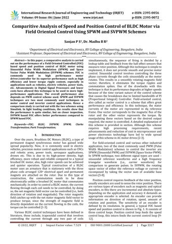
Positioncontrolrequiresfeedbackoftherotorposition, usuallyencodersareusedtosensetherotorposition.There arevarioustypesofencoderssuchasmagneticandoptical encoders,in thisthere are incremental and absolutetypes. Depending on the application and accuracy it demands an appropriate encoder is selected. An encoder can provide information on direction of rotation, speed, amount of rotation and position. The sensitivity of an encoder is defined by its resolution. In general, a typical FOC based speedandpositioncontrol isshowninFig. 1.Itconsistsof three control loops. Position control loop feeds the speed control loop, this inturn feeds the current control loop [9 12]
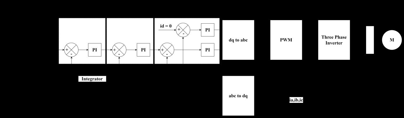
Let’s assume a system of BLDC motor connected via a three phaseinverterandpoweredbyaDCsourceasshown in Fig.2. To model the motor, consider a star connected configuration for the BLDC motor [2] and assuming a balancedthreephasesystem,then,R=Ra+Rb+Rc. (1) (2) (3)
Inequation(1 3),
Va, Vb, Vc = phase voltages
R = Armature resistance
L = Armature self inductance


M = Mutual inductance
Ia, ib, ic = phase current
Ea, eb, ec = motor back emf
Thebackemfofthemotoriswrittenasshownin(4 7) (4) (5)
The electrical angle, θe = (P/2)θm, where θm is the mechanicalangleoftherotorandParethenumberofpole pairs.Thefunctiongivenbyfin(7)givesthebackemfthat istrapezoidalinnatureforphaseAofthemotor.Kwisthe backemfconstantandωistherotorspeed.
The electromagnetic torque in both electrical form and mechanicalformisgivenin(8)and(9)respectively. (8) (9)
Inthis,
P = Number of pole pairs
TL = Load Torque
J = Moment of Inertia
B = Friction Constant
Fig.3 shows the vector representation of the stator current in abc, alpha beta and dq reference frames. For conversion from abc to alpha beta reference frame, only two instantaneous current vectors are sufficient, in this case phase currents of a and b. Phase c current can be computedusingthecurrentrelationshownin(10). (10)
Using Clarke’s transformation, the phase vectors are converted to alpha beta orthogonal reference frame (11 12).
(12)
Sinusoidal Pulse Width Modulation, is one of the most commonly used technique for motor control and inverter applications. Implementation of this technique is simple and processing requirements are less. The sinusoidal reference waveforms are compared with a high frequency triangularcarrier waveformto obtain the switching pulses fortherespectiveswitches.
Using Park’s transformation, the vectors are converted fromalpha betacoordinatesystemtodqcoordinatesystem (13 14) (13) (14)
Here,θistheinstantaneousrotorpositionangle,alsoin thedqreferenceframe,thequantitiesaretimeinvariant.By controlling/modifying the quadrature component of the current, the torque can be controlled. By controlling the directcomponent,therotorfluxcanbecontrolled.
In order to maximize torque and overall efficiency, the direct component must be ideally maintained at zero and quadrature component is generated based on torque and speed requirements. The reference values are compared withactualvaluesandviaaPIcontroller,thecorresponding voltage is calculated. The voltage in dq reference frame is converted back to alpha beta coordinate system using Inverse Park’s transformation as shown (15 16). This is typicallyusedtogeneratethegatepulsesusingSVPWM. (15) (16)


Inordertoconvertfromalpha betacoordinatesystem to abc, Inverse Clarke’s transformation is used as shown (17 19).ThisisusedtogeneratetheSPWMfortheinverter. (17) (18) (19)
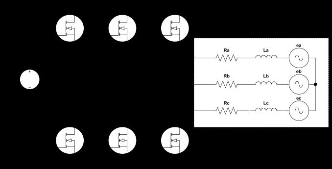
Space Vector Pulse Width Modulation is a more advancedtechniquecomparedtotheSPWMtechnique.The added complexity offers many advantages such as better utilization of DC bus voltage, lower harmonics and better flexibility.Fig.4showsa spacevectorrepresentationofthe inverter system with six sectors. The reference vector rotates with an angular velocity against the stationary alpha beta reference frame. By controlling the frequency andmagnitudeofvref,themagnitudeandfrequencyofthe correspondingfundamentalcomponentisvaried[6 8] The requiredoutputvoltageofeachphaseisshownin(20 22).
(20) (21) (22)
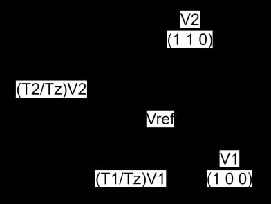
Vrefiscalculatedusing(23)andtheFig.5visualizesthe representationofsector1
Fig.5.Sector1Representation
Volume: 09 Issue: 06 | June 2022 www.irjet.net p ISSN: 2395 0072
(23)
Inthisθ=ωt=2πft (24)
In this Tz is the time period of the PWM signal or the reciprocaloftheswitchingfrequencyfs(i.e.,Tz=1/fs).The anglebetweenthesectorsisgivenbyϕwithrangebetween 0o to60o .


(25)
(26 28)isusedtodeterminetheswitchingperiod. (26) (27) (28)
ThesimulationstudiesarecarriedoutusingSimulink.In accordance to fig, the models for the comparison studies using the SPWM and SVPWM based speed and position control of BLDC motor is shown in Fig.6. The Simulink model consists of PMBLDC motor configured for trapezoidal back emf, stator resistance of 0.01ohms and inductance of 40uH. For the inverter, a two level inverter block is used, powered by a DC source of 12V. The transformations are directly performed using the conversion blocks available in Simulink. The PWM scheme is directly implemented using the PWM modulator block that offers both SVPWM and SPWM capabilities. The PWM scheme is changed between studies to perform the comparison study. The switching frequency is set at 8kHz. There are three control loops, one current control loop, speed control loop and position control loop connected in cascaded configuration. In order to keep track of the
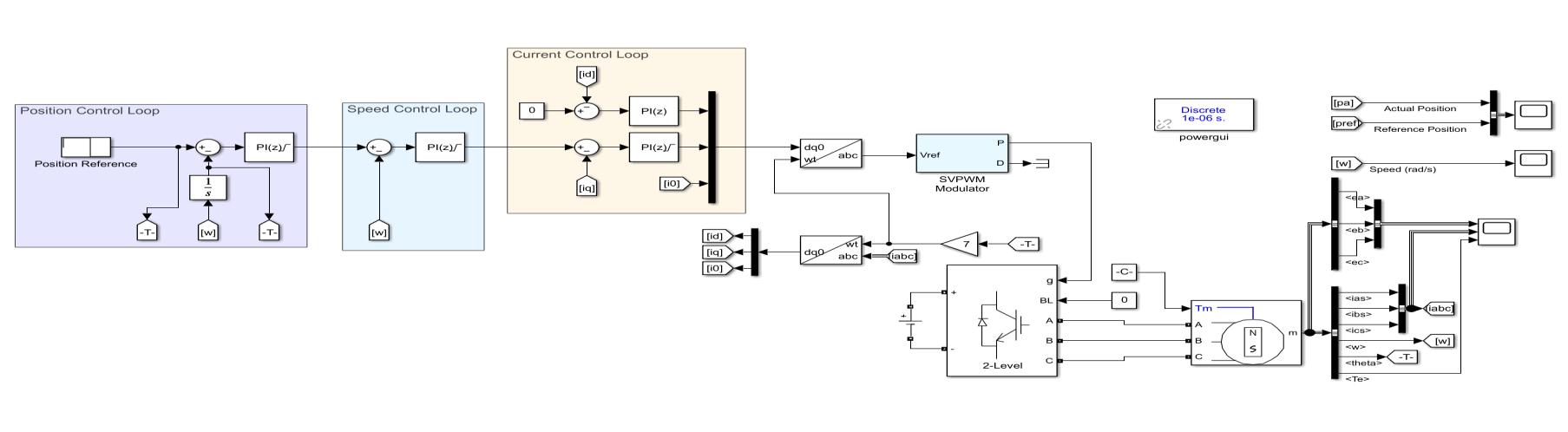
position,theintegralofspeedistaken.Aconstanttorqueof 0.008Nm is applied on the motor with a total simulation time of 5 seconds. Using a stair generator block, the referencepositionisgenerated.From0,at0.1seconds,the position is set to 4 radians or 4 revolutions of the rotor shaft. At 2 seconds, the rotor position is set to 4 radians andissetbackto0radiansat3.5seconds.ThePIcontroller of the current control loop is tuned using a separate MATLAB script. The speed and position control loop are tuned by trial and error method The model is run at constant speed next to obtain the back emf and electromagnetictorquewaveforms.
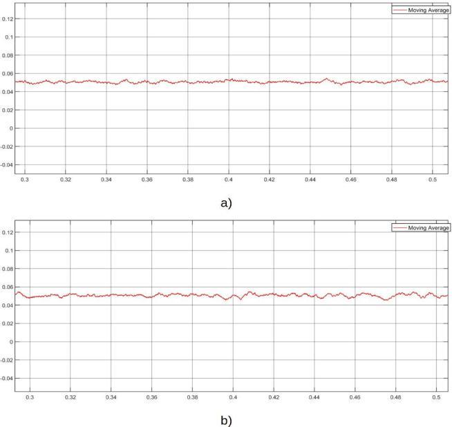
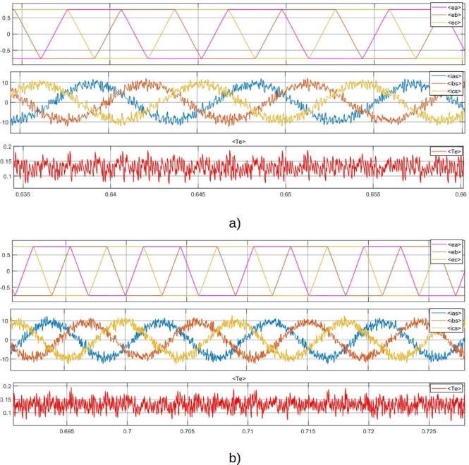
Fig.7 shows the waveforms related to the motor. In order, thefirstwaveformshows theback emf,thephasecurrents and the electromagnetic torque. At the commanded positions, the waveforms using both SPWM and SVPWM look similar, upon closer inspection, the electromagnetic torque ripple is relatively less in SVPWM scheme. During position change, the current draw increases to reach the desired position, the current starts dropping once the positional error start reducing. Spikes in electromagnetic torque is seen during position changes. Fig. 8 and Fig.9 shows the comparison between speed and position waveforms respectively. The rotor speed waveforms show thespeedincreasingduringpositionchangesandreducing when positional error reduces. The position waveforms showtheactualpositionandreferencepositionwaveforms. The control system is able to track the reference positions accuratelyandnoovershootsoccur. Asimilarconclusionis drawn by comparison of these waveforms. This similar performance is due to the light loading conditions. Fig.10 shows a comparison of the motor parameters at constant speed of 100 rad/sec with increased loading of 0.08Nm compared to the 0.008Nm previously. In this case, only a small difference is seen in the electromagnetic torque. The back emf at this loading is at 0.7V and the current draw is close to 10A(peak). The overall torque ripple is less in SVPWM compared to SPWM. This is verified by taking a movingaverageoftheelectromagnetictorquetoreducethe noise caused by switching as shown in Fig.11. There are a lot less variations in the SVPWM based FOC compared to
International Research Journal of Engineering and Technology (IRJET) e ISSN: 2395 0056
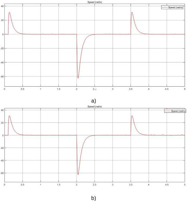
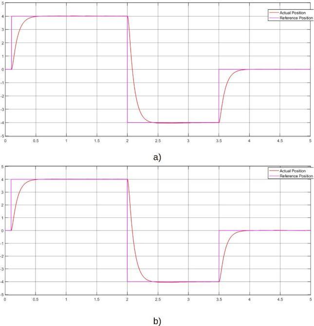
Fig.7 BackEMF,StatorCurrent,ElectromagneticTorqueWaveformsoftheBLDCMotora)SVPWMb)SPWM
SPWMbasedFOC.
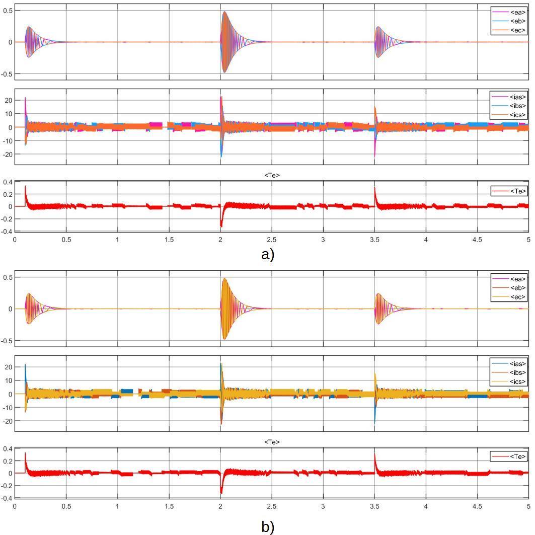
Fig.8.SpeedWaveforminrad/seca)SVPWMb)SPWM
Volume: 09 Issue: 06 | June 2022 www.irjet.net p ISSN: 2395 0072 © 2022, IRJET | Impact Factor value: 7.529 | ISO 9001:2008 Certified Journal | Page3321
Fig.9.ActualPosition(Red)andReferencePosition (Purple)Waveform a)SVPWMb)SPWM
General Block Diagram of Position and Speed Control of BLDC Motor Using FOCInternational Research Journal of Engineering and Technology (IRJET) e ISSN: 2395 0056
Fig.10.BackEMF,StatorCurrent,ElectromagneticTorque WaveformsoftheBLDCMotoratConstantSpeeda) SVPWMb)SPWM
Fig.11.ElectromagneticTorqueatConstantSpeeda) SVPWMb)SPWM
The comparison study of position and speed control of BLDC motor via FOC using SPWM and SVPWM has been carried out using Simulink and the corresponding output waveformsofcomparisonispresented.Inthisstudy,dueto lightloadingconditions,theperformanceoftheFOCbased algorithm usingbothSPWM and SVPWM schemeare quite similar. Small variations can be seen in the waveforms especially comparing the electromagnetic torque, the
Volume: 09 Issue: 06 | June 2022 www.irjet.net p ISSN: 2395 0072 © 2022, IRJET | Impact Factor value: 7.529 | ISO 9001:2008 Certified Journal | Page3322
SVPWM performs slightly better with less torque ripple compared to SPWM technique. The averaged torque waveform of SVPWM is relatively smoother compared to SPWM.
[1] Bimal K. Bose, “Modern Power Electronics and AC Drives,”2008
[2] Gujjar,MeghanaN.,andPradeepKumar."Comparative analysis of field oriented control of BLDC motor using SPWM and SVPWM techniques." In 2017 2nd IEEE International Conference on Recent Trends in Electronics,Information&CommunicationTechnology (RTEICT),pp.924 929.IEEE,2017.
[3] Kiran, Yadu, and Dr PS Puttaswamy. "A review of brushless motor control techniques." International JournalofAdvancedResearchinElectrical,Electronics and Instrumentation Engineering 3, no. 8 (2014): 10963 10971.
[4] Singh, Bhim, and Sanjeev Singh. "State of the art on permanent magnet brushless DC motor drives." journalofpowerelectronics9,no.1(2009):1 17.
[5] Lazor, Marek, and Marek Štulrajter. "Modified field oriented control for smooth torque operation of a BLDC motor." In 2014 ELEKTRO, pp. 180 185. IEEE, 2014.
[6] John, Joseph P., S. Suresh Kumar, and B. Jaya. "Space vectormodulationbasedfieldorientedcontrolscheme for brushless DC motors." In 2011 International Conference on Emerging Trends in Electrical and ComputerTechnology,pp.346 351.IEEE,2011.
[7] Li, Bo, and Chen Wang. "Comparative analysis on PMSMcontrolsystembasedonSPWMandSVPWM."In 2016 Chinese Control and Decision Conference (CCDC),pp.5071 5075.IEEE,2016.
[8] Ting, Naim Suleyman, Yusuf Yasa, Ismail Aksoy, and YakupSahin."ComparisonofSVPWM,SPWMandHCC control techniques in power control of PMSG used in wind turbine systems." In 2015 Intl Aegean Conference on Electrical Machines & Power Electronics (ACEMP), 2015 Intl Conference on Optimization of Electrical & Electronic Equipment (OPTIM) & 2015 Intl Symposium on Advanced Electromechanical Motion Systems (ELECTROMOTION),pp.69 74.IEEE,2015.
[9] Yun, Si Young, Ho Joon Lee, Jung Ho Han, and Ju Lee. "PositioncontroloflowcostbrushlessDCMotorusing Hall sensor." In 2012 Sixth International Conference on Electromagnetic Field Problems and Applications, pp.1 4.IEEE,2012.
International Research Journal of Engineering and Technology (IRJET) e ISSN: 2395 0056
Volume: 09 Issue: 06 | June 2022 www.irjet.net p ISSN: 2395 0072
[10] Ganesh, Chandramouleeswaran, and Sanjib Kumar Patnaik. "A simple first order compensator for brushless direct current drive based position control system." Journal of Vibration and Control 21, no. 4 (2015):647 661.
[11] Gamazo Real, José Carlos, Ernesto Vázquez Sánchez, and Jaime Gómez Gil. "Position and speed control of brushless DC motors using sensorless techniques and application trends." sensors 10, no. 7 (2010): 6901 6947.
[12] Sharma, Pragati K., and A. S. Sindekar. "Performance analysisandcomparisonofBLDCmotordriveusingPI and FOC." In 2016 International Conference on Global Trends in Signal Processing, Information Computing and Communication (ICGTSPICC), pp. 485 492. IEEE, 2016.