International Research Journal of Engineering and Technology (IRJET) Volume: 09 Issue: 06 | June 2022 www.irjet.net
e-ISSN: 2395-0056 p-ISSN: 2395-0072
Time Controlled DC Power Supply Using 555 Timer Shrihari. S1, Venkateshan. R2 1,2Department
of ECE, PSG College of Technology, Coimbatore-641004, India.
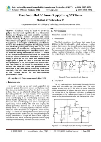
------------------------------------------------------------------------***-------------------------------------------------------------------II. METHODOLOGY gadgets has increased significantly. In a lithium-ion The system consists of two blocks namely battery, overcharging can create unstable conditions inside the battery, increase pressure and cause A. Power supply thermal runaway. Most phone manufacturers preach “Do not leave your phone connected to the charger for This block contains a transformer that steps down long periods or overnight” and “Keeping your battery 230V AC to 5V DC, followed by which we have a rectifier level as close to the middle (30% to 70%) as possible section that removes the ripples from the input signal, the can effectively prolong the battery life”. So, to solve next section has a capacitor filter to reduce the voltage this problem, we should have a timing mechanism that fluctuations, and the last section of power supply block is a automatically shuts the power after the desired time. voltage regulator which gives a constant voltage of 5V in To make this timing mechanism we used a 555 Timer the output despite the variations in the input voltage. IC as a monostable multivibrator which has one stable state and a quasi-stable state. The output of the power supply is given to the 555 timer and whenever the trigger pulse is given the timer is activated, which in turn gives power to the load only for that desired time. The time delay of the circuit is determined by the resistor and capacitor value. The potentiometer is used here to vary the resistor value and in turn the time delay. The 16 x 2 LCD will display the time delay at the current instant for the corresponding potentiometer value.
Abstract—In today’s world, the need for electronic
Figure 1: Power supply-Circuit diagram
Keywords—555 Timer, power supply, 16 x 2 LCD
B. Timer Block
I. INTRODUCTION
The 555 timer used here is in monostable multivibrator mode with one stable and quasi-stable state. The input voltage to the timer is 5V DC which is taken from the power supply block. Whenever a trigger pulse is applied to the trigger pin of the 555 timer, the timer produces the output voltage to the load circuit with a specific time delay based on the potentiometer value and the capacitor value.
In today’s world, we are very much dependent on electronic gadgets like mobile phones and laptops, which have become a significant part of our life. So it is essential to know how we can effectively utilize these devices to have a longer life. The one main reason a device ages is its battery and to sustain good battery health we need to avoid overcharging it as overcharging decreases the battery health significantly. Many phone manufacturers have said that overcharging your phone overnight can significantly reduce battery life, and also keeping the battery percentage between 30 - 70 % results in good battery health. To solve this problem, we have a solution. The basic idea is to control the output of a power supply using a 555 timer and making the electronic device charge to a specific set time by the user, by doing this the power supply terminates to charge the device after a specific amount of time, which eventually prevents overcharging and improves the battery life of the electronic devices.
Figure 2: 555 timer (Monostable mode) Circuit diagram © 2022, IRJET
|
Impact Factor value: 7.529
|
ISO 9001:2008 Certified Journal
|
Page 385