International Research Journal of Engineering and Technology (IRJET) e ISSN: 2395 0056

Volume: 09 Issue: 06 | Jun 2022 www.irjet.net p ISSN: 2395 0072
International Research Journal of Engineering and Technology (IRJET) e ISSN: 2395 0056
Volume: 09 Issue: 06 | Jun 2022 www.irjet.net p ISSN: 2395 0072
2
1 PG Student : Civil Engineering department, Ilahia College of Engineering and Technology, Mulavoor P.O, Muvattupuzha 686673
2 Assistant Professor : Civil Engineering department , Ilahia College of Engineering and Technology, Mulavoor P.O, Muvattupuzha 686673 ***
Abstract Tapered Concrete Filled Double Skin Tubular (CFDST) Columns are widely used in construction of modern buildings and structures due to their enhancement instability, high strength, light weight, andbetter cyclic performance. This paper presents a numerical investigation on the performance of tapered CFDST stub columns with locally corroded and surface corroded steel tubes by Finite Element method using ANSYS 16.1 WORKBENCH. Based on prior research the local corrosions in the steel tubes were represented by artificial notches and surface corrosion is represented by reducing the thickness of the steel tube. To develop the critical data needed for understanding the behavior of such stub columns, a group of 20 specimens were designed and analyzed. From the parametric analyses using the validated computer models the percentage decrease in strength for each specimen is calculated and strengthen the corroded section using CFRP
Key Words: CFDST, Local corrosion, Surface corrosion, Artificial notch and CFRP
Composite steel concrete construction is widely used in construction of modern buildings and structures, even in highlyseismicregions.Structuralmembersthataremadeup oftwoormoredifferentmaterialsareknownascomposite elements.Themainbenefitofcompositeelementsisthatthe propertiesofeachmaterialcanbecombinedtoformasingle unitthatperformsbetteroverallthanitsseparateconstituent parts. As a material, concrete works well in compression, but it haslessresistanceintension.Steel,however,isvery strong intension,evenwhen usedonlyinrelativelysmall amounts.Steel concretecompositeelementsuseconcrete's compressivestrengthalongsidesteel'sresistancetotension, andwhentiedtogetherthisresultsinahighlyefficientand lightweightunitthat iscommonlyusedforstructuressuch as multistorey buildings and bridges. There are several different types of composite column; the most common being a hollow section steel tube which is filled with concrete; or an open steel section encased in concrete CFDSTsarestructuralmembersthathaveadoublesteelskin withconcretesandwichedbetweenthetwosteeltubes.The concreteinfilladdstothecompressionresistanceofthesteel section, preventing the steel from buckling. Although the
combinationofsteel andconcreteacrosstheCFSTcolumn cross section is optimal from the structural performance perspective,itexposesthesteeltubedirectlytotheworking environmentwhichcanbecorrosive[1].Incomparisonwith the abundant investigations on the other aspects of the CFDSTcolumns,theresearchonthebehaviorsoftheCFDST columnswiththecorrodedsteeltubesisfairlyscarce,very limitedworkhasbeendonefortheCFSTcolumnswiththe steel tubes locally corroded[1 2] Deterioration due to corrosionisaseriousproblemforallstructuresthatcauses enormous economic, social and environmental losses. Aggressive environment conditions and inadequate maintenance are the main reason for corrosion related damages. The costs attributed to corrosion damages of all kinds are estimated to be 3% to 5% of industrialized countriesgrossnationalproducts.
Thebehavioroftaperedconcretefilleddoubleskintubular columnssubjectedtolocalgroovecorrosionintheformof artificial notches are studied. And also, the comparative study on local groove corrosion and surface corrosion in tapered CFDST columns are studied Further, the results frompastsurveysshowthatlocalcorrosiontriggeredmore than80%ofthereportedcorrosionaccidents[1].Therefore, there is an urgent need to extend the research from the CFDSTcolumnswiththeuniformlycorrodedsteeltubesto those with locally corroded steel tubes. Due to those damages found out how much amount of strength is lost from the member, change in the behavior of column and CFRP method is proposed to strengthen the damaged taperedCFDSTcolumn.Modellingandanalysisaredonein FiniteElement(FE)SoftwareANSYS16.1
1) Performingtheaxialloadandeccentricloadstudy of corrosion damaged tapered CFDST under local grovecorrosion
2) Studyofsurfaceareacorrosioninformofartificial wayofreducingthethicknessinsteelaremade
3) Strengthening methods proposed to overcome thesedamagesaccordingtotheseverity.
International Research Journal of Engineering and Technology (IRJET) e ISSN: 2395 0056
Volume: 09 Issue: 06 | Jun 2022 www.irjet.net p ISSN: 2395 0072
Inthisstudy,theliteraturereviewisdone,themodelling of specimen is done using ANSYS 16.1 WORKBENCH, conductingparameterstudyusingANSYS16.1WORKBENCH andtheinterpretationofresults.
Tapered Concrete Filled Double Skin Tubular columns withlocalgroovecorrosionintheformofartificialnotches aremodelled.18modelsarecreatedusingANSYSsoftware with artificial notches in different direction (vertical, horizontal, inclined) and at different depth (top, middle, bottom).TheconcretetypeusedisM30GradeConcrete
For the specimen the properties of concrete were Young’s modulus(E)=2.33×10⁵MPa,Poisson’sratio(µ)=0.2,Density (ρ)=2400kg/m3andGradeofconcreteisM30.Andthesteel tube specimen with following material properties is used Young’smodulus(E)=1.96×10⁵MPa,Poisson’sratio(µ) = 0.3,Density(ρ)=7860kg/m3
Geometrical
Model Length (mm) Width (mm) Thickness (mm) SC 150 110 0.28 150 110 0.28
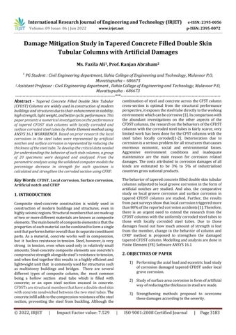
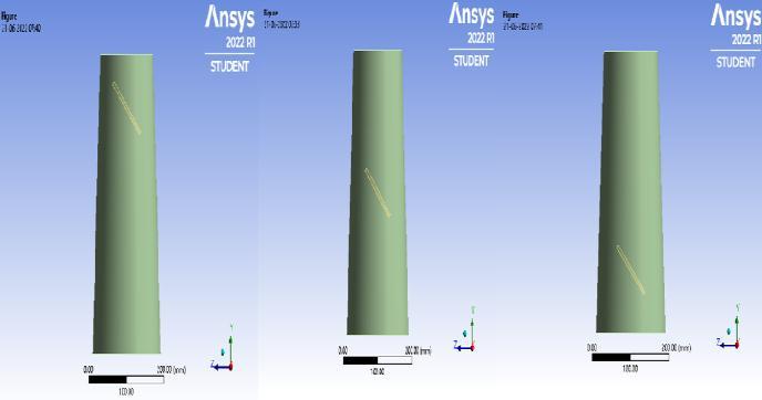
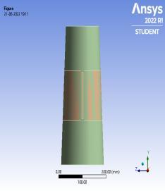
TaperedCFDSTcolumnsaremodelledinANSYSsoftware. Thelocalgroovecorrosionisprovidedinvertical,horizontal and inclined direction at different depths of the tapered CFDST columns. Length of column is taken as 420mm, thickness of the steel inner and outer is 3mm and 5mm respectively.Thesurfacecorrosionisprovidedintheformof reducingthethicknessofthesteeltubeModellingofconcrete andsteel is donebyusing element types of SOLID186and hexahedronmeshingisprovided.Programcontrolledcoarse meshisadoptedformeshingthecolumns.Loadisappliedas displacement of 10mm according to displacement convergencemethod.
(a) (b) (c)
Fig 1:ModelofTaperedCFDSTcolumnswithvertical notchat(a)Top(b)Middle(c)Bottom
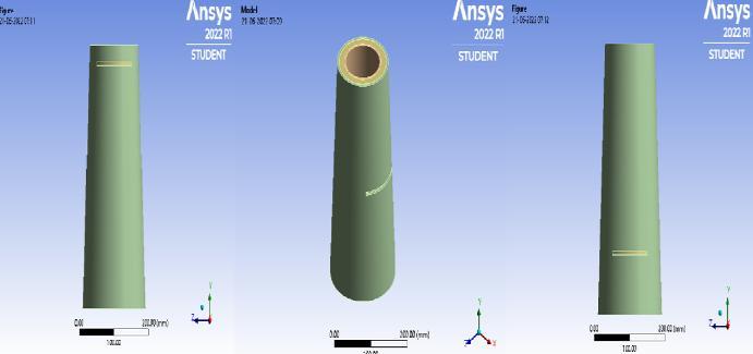
Fig 2:ModelofTaperedCFDSTcolumnswithhorizonal notchat(a)Top(b)Middle(c)Bottom
International Research Journal of Engineering and Technology (IRJET) e ISSN: 2395 0056
Volume: 09 Issue: 06 | Jun 2022 www.irjet.net p ISSN: 2395 0072
Fig 3:ModelofTaperedCFDSTcolumnswithvertical notchat(a)Top(b)Middle(c)Bottom
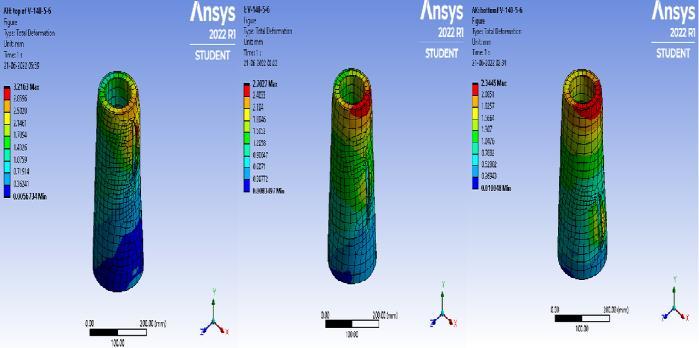
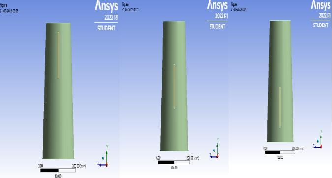
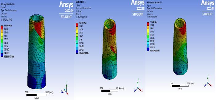
AnalysisiscarriedouttostudytheperformanceofTapered Concrete Filled Double Skin Tubular Columns with local groovecorrosionattopmiddleandbottomofthecolumnand surfacecorrosionofthecolumn.Nonlinearstaticsstructural analysisiscarriedoutinANSYSsoftware.Deformationand loadcarryingcapacityisstudied
Fig 6:DeformationofTaperedCFDSTcolumnswith inclinednotchat(a)Top(b)Middle(c)Bottom
5.1
The axial loading capacity of Tapered CFDST column subjectedtolocalgroovecorrosionandsurfacecorrosionwas determined from FE analysis. Table 4 and 5 shows the maximum load and deflection of axially loaded Tapered CFDST column under local groove corrosion and surface corrosion
TABLE-4: Maximumloadanddeflectionofaxiallyloaded localcorrodedTaperedCFDSTcolumn
Model Deformation (mm) Load (kN) % Decrease inload NP3 1.40 1197.8 1
TOP V 140 5 6 1.83 1152.8 3.75 V 140 5 6 1.64 1143.6 4.52 BOTTOM V 140 5 6 2.03 1148.6 4.10
TOP H 140 5 6 1.08 1047.3 12.56 H 140 5 6 1.12 1031.6 13.87 BOTTOM H 140 5 6 0.87 1112 7.16 TOP IN 140 5 6 1.10 1011.3 15.57 IN 140 5 6 1.44 1072.8 10.43 BOTTOM IN 140 5 6 0.87327 1112 7.16
TABLE 5: Maximumloadanddeflectionofaxiallyloaded surfacecorrodedTaperedCFDSTcolumn
Model Deformation (mm) Load (kN) % Decrease inload
NP3 1.40 1197.8 1 V 140 5 6 1.64 1143.6 4.52 SC 150 110 0.28 1.216 1165.8 2.67
International Research Journal of Engineering and Technology (IRJET) e ISSN: 2395 0056
Volume: 09 Issue: 06 | Jun 2022 www.irjet.net p ISSN: 2395 0072
FromTable4,TaperedCFDSTcolumnswithverticalgroove corrosionhasmoreloadcarryingcapacitythantheTapered CFDST column with horizontal and inclined local groove corrosion. The load carrying capacity of Tapered CFDST column with horizontal notch at the middle and inclined notch at top has percentage decrease of load is 23.43 and 35.81respectivelywhencomparedwiththenon corroded NP3TaperedCFDSTcolumn
Fig -7:Load Deformationcurveofverticalnotchin TaperedCFDSTcolumn.
FromTable5,TaperedCFDSTcolumnwithsurfacecorrosion showsmoreloadcarryingcapacitythantheTaperedCFDST columnwithlocalgroovecorrosion.Onlya2.6%ofdecrease inloadcarryingcapacityinsurfacecorrodedTaperedCFDST column but there is a 4.5% of decrease in load carrying capacitywhensubjectedtolocalgroovecorrosion.
The eccentric loading capacity of Tapered CFDST column subjectedtolocalgroovecorrosionandsurfacecorrosionwas determinedfromFEanalysis.Table6showsthemaximum loadanddeflectionofaxiallyloadedTaperedCFDSTcolumn underlocalgroovecorrosion
TABLE 6: Maximumloadanddeflectionofeccentric loadedlocalcorrodedTaperedCFDSTcolumn
Fig 8:Load Deformationcurveofhorizontalnotchin TaperedCFDSTcolumn.
Model Deformation (mm) Load (kN) % Decrease inload NP3 2.1 424.02 1 V 140 5 6 2.51 487.42 14.95 H 140 5 6 1.51 523.39 23.43 IN 140 5 6 2.68 575.88 35.81
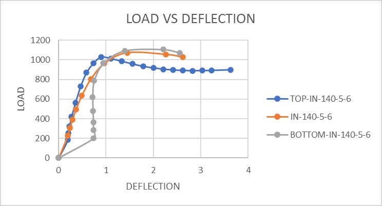
Fig 9:Load Deformationcurveofinclinednotchin TaperedCFDSTcolumn.
Fig 11:EccentricLoad DeformationcurveofTapered CFDSTcolumn.
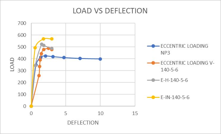
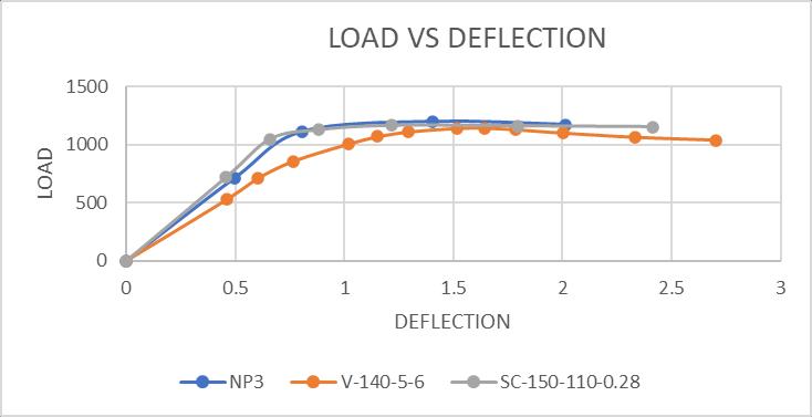
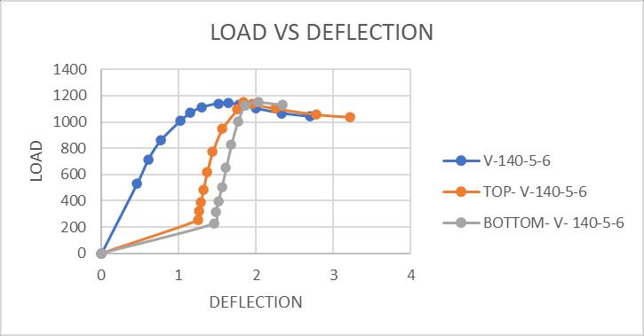
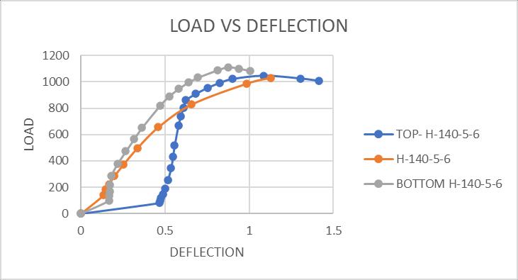
Fig -10:Load Deformationcurveofsurfacecorroded TaperedCFDSTcolumn.
2022, IRJET | Impact Factor value: 7.529 | ISO 9001:2008 Certified Journal
International Research Journal of Engineering and Technology (IRJET) e ISSN: 2395 0056
Volume: 09 Issue: 06 | Jun 2022 www.irjet.net p ISSN: 2395 0072
FromTable6TaperedCFDSTcolumnswithverticalgroove corrosionhasmoreeccentricloadcarryingcapacitythanthe Tapered CFDST column with horizontal and inclined local groove corrosion. The load carrying capacity of Tapered CFDST column with horizontal notch at the middle and inclined notch at top has percentage decrease of load is 23.43and35.81respectivelywhencomparedwiththenon corrodedNP3TaperedCFDSTcolumn
ThematerialpropertiesoftheCFRPlaminatesareimproved due to its wide range of usage in construction industries. Carbonfibrereinforcedpolymerhasahighercompression strengththanmaterialslikealuminiumandsteel.Thismeans thatcarbonfibrehandlesmorepressurethanitstraditional alternatives. It islight weight and it has highfatigue resistanceand the flexible carbon fibres crack far less frequently than traditional alternatives like concrete and steel(especiallywhenthey’resubjecttorepeatload bearing weight)
TensileStrength(MPa)1240
ModulusofElasticity(MPa)91700
Poisson'sRatio0.3
BulkModulus(MPa)76417
ShearModulus(MPa)35269
Thickness(mm)1.27
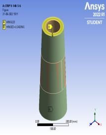
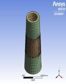
Fig 12:(a)Modelling(b)Meshingand(c)Loading diagramofV 140 5 6usingCFRP
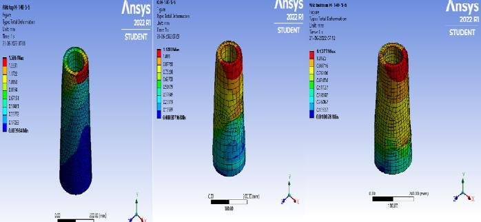
AnalysisiscarriedouttostudytheperformanceofTapered ConcreteFilledDoubleSkinTubularcolumnswithCFRPto strengthen.Nonlinearstaticstructuralanalysisiscarriedout inANSYSsoftware.Deformationand load carryingcapacity isstudied.Thedeformationdiagramsofcolumnspecimens aregivenbelow
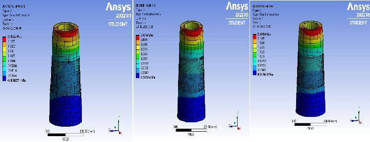
(a) (b) (c)
Fig 13:DeformationofTaperedCFDSTcolumnswith verticalhorizontalandinclinednotchusingCFRP.
TheaxialloadingcapacityofrepairedTaperedCFDSTcolumn withCFRPsubjectedtolocalgroovecorrosionandsurface corrosionwasdeterminedfromFEanalysis.Table7shows the maximum load, deflection and % increase in axially loadedTaperedCFDSTcolumnunderlocalgroovecorrosion repairedusingCFRP
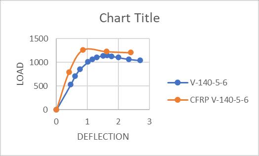
TABLE 7: Maximumloadanddeflectionofaxiallyloaded verticallocalcorrodedTaperedCFDSTcolumnusingCFRP
Deformation (mm) Load(kN) %Increasein load V 140 5 6 1.64 1143.6 1 CFRPV 140 5 6 1.62 1227.8 7.3
TABLE-8: Maximumloadanddeflectionofaxiallyloaded horizontallocalcorrodedTaperedCFDSTcolumnusing CFRP
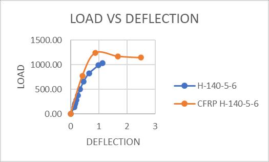
%Increasein load H 140 5 6 1.12 1031.6 1 CFRPH 140 5 6 0.87 1243.1 20.5
Deformation (mm) Load(kN)
TABLE-9: Maximumloadanddeflectionofaxiallyloaded inclinedlocalcorrodedTaperedCFDSTcolumnusingCFRP
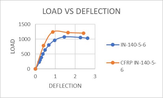
%Increasein load IN 140 5 6 1.48 1072.8 1 CFRPIN 140 5 6 0.87 1247 16.2
Deformation (mm) Load(kN)
2022, IRJET | Impact Factor value: 7.529 | ISO 9001:2008 Certified Journal
International Research Journal of Engineering and Technology (IRJET)
e ISSN: 2395 0056
Volume: 09 Issue: 06 | Jun 2022 www.irjet.net p ISSN: 2395 0072
TaperedConcreteFilledDoubleSkinTubularcolumnswith local groovecorrosionandsurfacecorrosionaremodelled andanalysed.Thecomparisonoflocalgroovecorrosionand surfacecorrosionarestudied.CFRPisusedforstrengthening thedamagedTaperedCFDSTcolumn.
Thefollowingconclusionsareobtained:
Fig 14:AxialLoad DeformationcurveofTaperedCFDST columnusingCFRP
Based on the research it was found that peak resistanceandductilityoftaperedCFDSTcolumns can be significantly reduced due to presence of horizontalandslantedartificialnotchinsteeltube. However,theinfluencesonthepeakresistanceand ductility become much less remarkable when the notchisalongtheverticaldirection.
The load carrying capacity of Tapered CFDST column with horizontal notch at the middle and inclinednotchattophaspercentagedecreaseofload is23.43and35.81%respectively
Localcorrosioncanbeactuallymoredetrimentalin CFDST columns since it causes asymmetric cross sectionpropertiesandaccordinglyleadstoeccentric loadingwhilecompromisingtheconfinementonthe concretefill.
Fig -15:AxialLoad DeformationcurveofTaperedCFDST columnusingCFRP
Tapered CFDST column with surface corrosion showsmoreloadcarryingcapacitythantheTapered CFDSTcolumnwithlocalgroovecorrosion.Onlya 2.6%ofdecreaseinloadcarryingcapacityinsurface corrodedTaperedCFDSTcolumnbutthereisa4.5% ofdecreaseinloadcarryingcapacitywhensubjected tolocalgroovecorrosion.
Moreover,ithasbeenreportedthatlocalcorrosion is more likely to occur compared with uniform corrosion
Using CFRP to rehabilitate the locally grooved tapered CFDST columns enable steel section to restorethelostcapacityandresistadditionalloads.
Fig 16:AxialLoad DeformationcurveofTaperedCFDST columnusingCFRP
Fromfigs14,15,16,damagedTaperedCFDSTcolumnwith CFRP shows more load carrying capacity in local groove corrosion.7.3%,20.5%,and16.2%increaseinloadcarrying capacitywhenwrappedwithCFRP.
I am thankful to my guide, Mr Ranjan Abraham, Asst. ProfessorinCivilEngineeringDepartmentofIlahiaCollege of Engineering, Mulavoor for his constant encouragement andableguidance.Also,Ithankmyparents,friendsetc.for theircontinuoussupportinmakingthisworkasuccess.
International Research Journal of Engineering and Technology (IRJET) e ISSN: 2395 0056
[1] Haijia Huang Lanhui Guo, Bing Qu, Chen Jia and MohamedElchalakani“Testsofcircularconcrete filled steel tubular stub columns with artificial notches representinglocalcorrosions,”EngineeringStructures, vol.242,1September2021112598.
[2] Hossein Karagah, Cheng Shi, Mina Dawood and AbdeldjelilBelarbi“Experimentalinvestigationofshort steel columns with localized corrosion”, Thin Walled Structures,vol.87,February2015
[3] Yong Bo Zhang, Lin Hai Han and Wei LiR. Nicole, “Analytical behaviour of tapered CFDST stub columns under axially partial compression,” Journal of ConstructionalSteelResearch,vol.139,December2017
[4] FangYuan,MengchengChen⁎,HongHuang,LiXie,Chao WangK. Elissa, “Circular concrete filled steel tubular (CFST)columnsundercyclicloadandacidrainattack: Test simulation,” Thin Walled Structures, vol.122, November2017
[5] TalhaEkmekyapar,BaraaJ.M,AL Eliwi“Concretefilled double circular steel tube (CFDCST) stub columns,” EngineeringStructures,vol135December2017
[6] Xiao LingZhao,Le WeiTongandXing YiWang“CFDST stub columns subjected to large deformation axial loading” ,EngineeringStructures,692 703.2009
[7] M.Pagoulatou,T.Sheehan,X.H.DaiandD.Lam“Finite element analysis on the capacity of circular concrete filleddouble skinsteeltubular(CFDST)stubcolumns” , EngineeringStructures,102 112.2014
[8] Wei Li, Lin Hai Han and Tak Ming Chan “Tensile behaviour of concrete filled double skin steel tubular member” .JournalofConstructionalSteelResearch.2014
[9] Qing XenRin,ChaoHou,DennisLamand Lin HaiHan “Experiments on the bearing capacity of tapered concrete filled double skin steel tubular stub CFDST columns”, Steel and Composite structures, 667 686 2014
Volume: 09 Issue: 06 | Jun 2022 www.irjet.net p ISSN: 2395 0072 © 2022, IRJET | Impact Factor value: 7.529 | ISO 9001:2008 Certified Journal