International Research Journal of Engineering and Technology (IRJET) e ISSN: 2395 0056

Volume: 09 Issue: 06 | Jun 2022 www.irjet.net p ISSN: 2395 0072
International Research Journal of Engineering and Technology (IRJET) e ISSN: 2395 0056
Volume: 09 Issue: 06 | Jun 2022 www.irjet.net p ISSN: 2395 0072
1Mtech student, Structural and construction management, MGMCET, Pampakuda P.O, Muvattupuzha, Kerala, India
2Assistant professor, Civil Department, MGMCET, Pampakuda P.O, Muvattupuzha, Kerala, India
3Assistant professor, Civil Department, MGMCET, Pampakuda P.O, Muvattupuzha, Kerala, India ***
Abstract Diagrid structures are designed with new geometric layouts. The flexibility and aesthetic appearance make it unique. In this paper comparing four grid systems such as O Grid, Elliptical grid, concentric grid and Forward grid with ANSYS workbench 2021 R2. Also the connection bracings are provided with three shapes such as H, I and C. Analysis with an outrigger with O Grid H, I, C shape is also performed. Analysis is mainly used to determine the seismic performance of models, energy absorption capacity and ductility of the models. After analysis the result obtained that, by comparing with other models O Grid models are between the forward and elliptical bracing systems, and have appropriate load bearing and can absorbedgreatenergywith their axial and flexural behaviour. The utility performance of OG rid with C section shows better result.
Key Words: Diagrid Grid, O Grid, Elliptical bracing system, Grid bracing system, forward bracing seismic response.
Diagridconstructionshaveframesarrangedinatriangular modular quadrilateral. These triangular members resist verticalandlateralloads.Becausetherearenoelementsor columns. A modular framework consists of larger interlockingsteels.Thissystemhasordoesnothavevertical components, and since the primary load components are members,theyalsohavelateralsupport.Tiesarecommonly usedtostabilizeabuildingstructureagainstlateralloading. Themainfunctionofthestrutsistostabilizethestructure and prevent its collapse. Various fastening systems are currently in use. Depending on the shape, the braces are diagonalbracings,X shaped,K shaped shaped,ellipticaland O shaped. In this paper different bracing systems are numericallyanalysed.
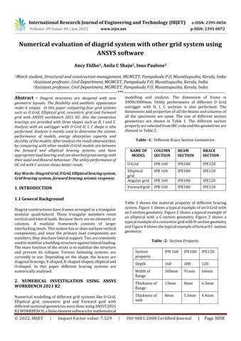
Numerical modelling of different gridsystemslike OGrid, Elliptical grid, concentric grid and Forward grid with differentsectionalgeometriesweredoneusingANSYS2021 R2WORKBENCH,afiniteelementsoftwareformathematical
modelling and analysis. The dimension of frame is 3000x3000mm. Utility performance of different O Grid outrigger with H, I, C sections is also performed. The dimensionsandpropertiesofallthebeamsandcolumnsof all the specimens are same. The size of different section geometries are shown in Table 1. The different section propertyareselectedfromIBCcodeandthegeometriesare showedinTable2.
Table -1: DifferentBraceSectionGeometries.
NAME OF MODEL COLUMN SECTION BEAM SECTION BRACE SECTION
OGrid IPB160 IPE180 IPE120
Elliptical grid IPB160 IPE180 IPE120
Angulargrid IPB160 IPE180 IPE120
Forwardgrid IPB160 IPE180 IPE120
Table 3 shows the material property of different bracing system.Figure1showsatypicalexampleofanOGridwith anI sectiongeometry,Figure2showsatypicalexampleof an elliptical with a C section geometry, Figure 3 shows a typicalexampleofaconcentricgridwithH sectiongeometry andFigure4showsthetypicalexampleofforwardI section geometry.
Table 2: SectionProperty.
Section property
IPB160 IPE180 IPE120
Depth 160 180 120
Widthof flange 160mm 91mm 64mm
Thicknessof flange 13mm 8mm 6.3mm
Thicknessof web 8mm 5.3mm 4.4mm
International Research Journal of Engineering and Technology (IRJET) e ISSN: 2395 0056 Volume: 09 Issue: 06 | Jun 2022 www.irjet.net p ISSN: 2395 0072
Table -3: MaterialProperty.
Fig -4:ForwardgridwithI section
Anoutriggerisconstructedwith threestoreywithOGrid. OutriggerwithH,IandCsectionsweremodelled.Theheight ofeachlayeris3000mmanddiameterofOGridis2616mm. Thelengthofbeamis9000mm.forfirststoreythereisthree OGridsareprovided.Onthewholestructuretotallyof9O Grids are there. Figure 5 shows the modelled view of outriggerwithCsectiongeometry.
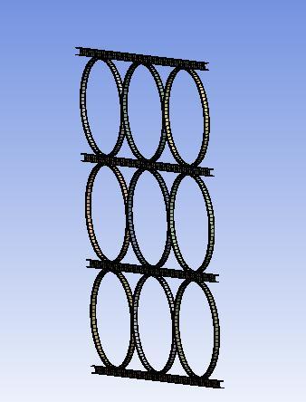
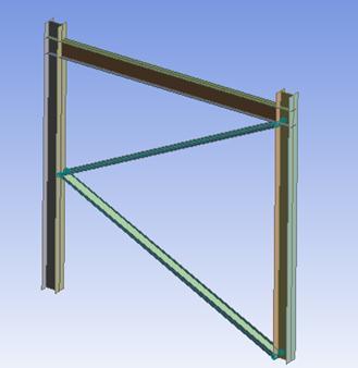
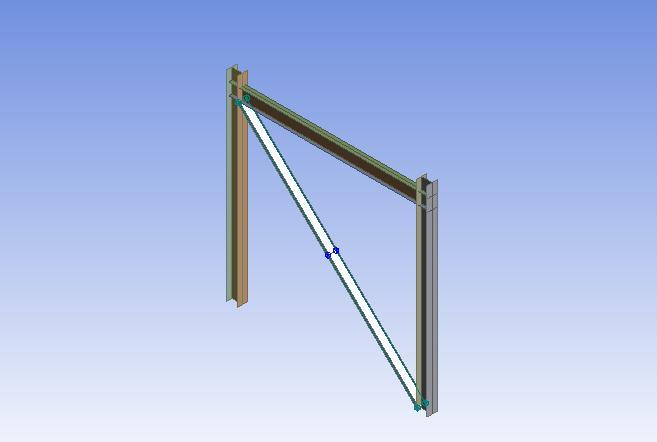
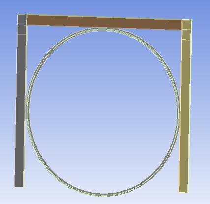
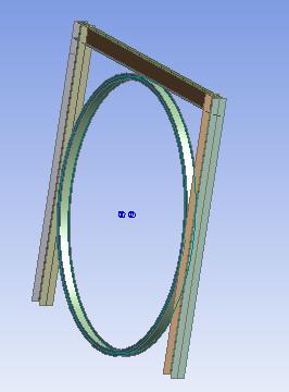
Fig -5:ModelledviewofsteelwithoutriggerwithC section
Herea100mmdisplacementisgiveninx direction.Similar loading conditions is given to twelve models. Also the support condition is fixed. A remote displacement is also provided. Figure 6 and 7 shows the loading pattern in Angular Isectionandinanoutriggergeometry.
International Research Journal of Engineering and Technology (IRJET) e ISSN: 2395 0056
Volume: 09 Issue: 06 | Jun 2022 www.irjet.net p ISSN: 2395 0072
Combination of O Grid Section
Fig -6 LoadingandboundaryconditionofAngulargrid

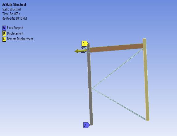
Fig 7 LoadingandboundaryconditionofOGridin outriggersystem
Theload displacementhysteresiscurvesofeachmodelare drawn by comparing the load deformation values of each model Chart1tochart4showstheobtainedvalues.
200000
100000
0
-100000
300000 -150 -100 -50 0 50 100 150 Force (N)
-200000
-300000
Deformation (mm)
O Grid-C O Grid-I O Grid-H
200000
100000
0
-100000
300000 -150 -100 -50 0 50 100 150 Force (N)
-200000
Chart 1:Load displacementhysteresiscurveofOGrid section -300000
Deformation (mm)
Elliptical-C Elliptical- I Elliptical -H
Chart -2:Load displacementhysteresiscurveofelliptical gridsection
100000
50000
0
150000 -200 -100 0 100 200 Force (N)
-50000
-100000
-150000
Deformation (mm)
Angle-C Angle-I Angle-H
Chart 3:Load displacementhysteresiscurveofangular gridsection
International Research Journal of Engineering and Technology (IRJET) e ISSN: 2395 0056
Chart 6showstheenergyabsorptioncapacityofeachmodel.
5.00E+05
0.00E+00
1.00E+06 -150 -100 -50 0 50 100 150 Force (N)
-5.00E+05
-1.00E+06
Deformation (mm)
Comparision of Forward sections Forward-C Forward-I Forward -H
Chart 4:Load displacementhysteresiscurveofforward gridsection
Theacceptanceofdifferentgeometriesofoutriggerwillbe analyzedusingANSYSsoftware.Table4showstheresultsof anoutriggersystems.
Table -4: Resultsofoutriggersystem
Name of model Total deformation (mm) Equivalent stress (MPa)
Outrigger I 112.03 653.34 Outrigger H 112.74 648.37 Outrigger C 112.44 751.27
1000000
Energy absorbed
500000
0
Ogrid-C Ogrid-I Ogrid-H Elliptical-C ELliptical-I Elliptical -H Angle-C Angle-I Angle-H Forward-C FOrward-I Forward-H
Name of models
Chart 6: Energyabsorptioncapacityofgridsystems
Force (N)
Force (N)
Chart5showsductilecharacteristicsofgridsystems.From thesemaximumforcevalueisobtained. 0
1000000 0 50 100 150
500000
Deformation (mm)
Ogrid-C O Grid-I Ogrid-H Elliptical -C Elliptical-I Elliptical-H Angle-C Angle-I Angle-H Forward-C Forward-I Forward-H
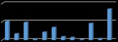
Chart -5: Ductilepropertiesofgridsections
100000
This can be simplified by comparing the maximum force valueofoutrigger H,outrigger I,outrigger C.Chart7shows themaximumforcevalueofdifferentgeometries. 0
150000 0 50 100 150
50000
Deformation (mm) Outrigger-I Outrigger -C Outrigger -H
Chart -7:Comparisonofoutriggerwithdifferent geometries
This study was mainly used to compare different types of bracing with different cross section geometries. When analysing,Gridbracesarebetweentheforwardandelliptical systems, and they have adequate load bearings and can absorbgreatenergywiththeiraxialandflexuralbehaviour. Unlike other braces, the structure and shape of O Grid braces, can be used in any part of the structure without removingarchitecturalspaceandarchitecturalform.Ogrid bracingsystemhasgoodductilityandstiffness.
Volume: 09 Issue: 06 | Jun 2022 www.irjet.net p ISSN: 2395 0072 © 2022, IRJET | Impact Factor value: 7.529 | ISO 9001:2008 Certified Journal | Page3061
International Research Journal of Engineering and Technology (IRJET) e ISSN: 2395 0056
Theresultofanalyticalstudywithdifferentbracingsection geometryisshowninfollowingconclusions:
The load deflection hysteresis curve of twelve models,OGridwithH,I,C sectionbracing,elliptical gridwithH,I,C sectionbracing,angularbracingH,I,C andforwardbracingwithH,I,C section.
[5] Maryam Boostani, Omid Rezaifar, Majid Gholhaki, “Experimental investigation of a new lateral bracing systemcalledOGridundercyclicloading”,Department of structural Engineering, Semnan University, Iran,2022.
Theresultshowedthatforward Hsectionbracing hasmoreductilityandenergyabsorptioncapacity, also the one with O Grid C section bracing shows comparableresult.
[6] Mahathi Heshmati, Alireza Khatami, Hamzeh Shakib,”Seismic performance assessment of tubular diagrid structures with varying angles in tall steel buildings”, Department of civil and Environmental Engineering,TarbiatModaresuniversity,Iran,2020.
Theresultobtainedfromtheanalysisofoutrigger showsthatOutrigger Csectionshowsthemaximum forceandequivalentstress.
[7] Qingxuan Shi, Yihui Ying, Bin Wang, ”Experimental investigationonthe seismic performanceofconcrete filledsteeltubularjointsindiagridstructures”,College ofcivilengineering,Xi’anUniversityofArchitecture& technology,Xi’an710055,China,2020
ThusthisOGrid Ctypeofbracingcanbeeffectively used in engineering structures in seismic prone areas which have the ability to withstand lateral loads.
IwishtothanktheManagement,PrincipalandHeadofCivil EngineeringDepartmentofMGMCollegeofEngineeringand Technology,affiliatedbyKeralaTechnologicalUniversityfor theirsupport.Thispaperisbasedontheworkcarriedoutby me (Ancy Eldho), as part of my PG course, under the guidance of Anila. C. Shaju and Inus Paulose (Assistant Professors, MGM College of Engineering and Technology, Muvattupuzha,Kerala).Iexpressmygratitudetowardsthem forvaluableguidance.
[1] Arshia Keivan, Yunfeng Zhang, “Nonlinear seismic performance of Y type self centering steel eccentri callybracedframebuildings”,DepartmentofCiviland Environmental Engineering, University of Maryland, CollegePark,USA.2018
[2] F.Albouye,“ExperimentalInvestigationofNewStruc turalSystem‘‘OGRID’’,DepartmentofCivilEngineering, SemnanUniversity,Iran,2016
[3] G.Lacidogna,D.Scaramozzino,A.Carpinteri,“Influence ofthegeometricalshapeonthestructuralbehaviourof diagridtallbuildingunderlateralandtorqueactions”, DepartmentofstructuralEngineering,CorsoDucaDegli Abruzzi24,Torino,Itely,2020.
[4] JorgeRuiz Garcíaa,EdénBojorquezb,EdgarCoronab. “Seismicbehaviourofsteeleccentricallybracedframes undersoft soilseismicsequences”,SoilDynamicsand EarthquakeEngineering115(2018)
Volume: 09 Issue: 06 | Jun 2022 www.irjet.net p ISSN: 2395 0072 © 2022, IRJET | Impact Factor value: 7.529 | ISO 9001:2008 Certified Journal