International Research Journal of Engineering and Technology (IRJET) e ISSN: 2395 0056

Volume: 09 Issue: 06 | Jun 2022 www.irjet.net p ISSN: 2395 0072
International Research Journal of Engineering and Technology (IRJET) e ISSN: 2395 0056
Volume: 09 Issue: 06 | Jun 2022 www.irjet.net p ISSN: 2395 0072
1,2Department of Mechanical Engineering, Priyadarshini College of Engineering, Nagpur 440019 Maharashtra, India
Abstract Raisin’s production is one of the leading agriculture industry but due to poor quality of raisins prices goes down and also it hamper the Indian raisins quality in global market. Poor quality of raisins due to the mixing of lower grade into higher grade, some impurities, moisture control not proper and its due to not properly sorting grades of raisins. The ability to sort raisins automatically is more efficient compared to the manual inspection which is slow, labour intensive, tedious and error prone. For that automatic, manual & S/W controlled raisins sorting machines available in market. In most of the cases sorting of right size of raisins has problem due to issues like wrong springs or over & not proper vibration due to wrong selection of vibration motor. One of the reason is linkages also. Lots of research’s have already been done to address issues & improve performance. And most the vibratory feeder research papers had addressed the performance issues with help of computer vision approach. In this paper, will check vibration calculations and check also selection of vibration motor.
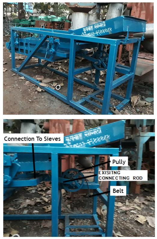
Raisinsneedprocessinglikecleaning,removalofdebrisand gradingintovarioussizes.Gradingofraisinsinvolvessorting raisins by size. Conventionally, this is done manually by womenwhoworkedforminimumwages.Thegradinghas beendonebythembasedonvisualinspectionandwhichis laborintensive,tediousanderrorprone.Nowaday’smanual toautomaticsorting machinesdevelopedforthispurpose calledraisingradingmachineandinmostofthedeveloped machine’ssortinghappenbyvibratingthesieves.Vibrating sievesarecommoninfoodindustriessortingequipmentbut mostcriticalpartinthatisvibratingmotorandgoodquality ofsievesaspergradesizesforraisinsits9mm,7mm&5mm wiremeshes.Combinationoffeedingandsortingofraisins machine consists of three motors, feeder, three sieves, blower,andbeltandpulleymechanism.Inthismachinefirst raisins are fed through a feeder, which has a rotor with a rubberpad.Amotordrivesthemechanism.Therubberpad hammerstheraisinstoremovethetwigsofraisins.These raisinsarethenpassedthroughtheblower,whichblowsthe dustandtwigsandcleanstheraisinswiththehelpofahigh pressureairflow.Theraisinsarefurthergradedaccordingto
size with the help of vibratory sieves with different wire meshing(9mm,7mmand5mm).Motiontovibratorysieve isgiventhrougha pulley beltdrive.Theraisinsseparated and graded over each sieve are collected in a different chamber. So in existing machine vibration in sieve not properits reducesthe efficiencyofmachinei.e.ithasless massflowrateofraisinasexpectedfromenduser.
Istudiedvarioussortingmachinesavailableinmarket,also studiedmachinesavailablefromglobalmanufacturermainly China manufactured machines have cheaper due to local manufactureuseofvibratormotor.Sortingmachinewhich mainlycontainsieveswithvibrationmotor.
Key Words: Raisin sorting, Grading of raisin, production & quality of raisin vibration system motorFig 1:ExistingSortingPlatform
International Research Journal of Engineering and Technology (IRJET) e ISSN: 2395 0056
Volume: 09 Issue: 06 | Jun 2022 www.irjet.net p ISSN: 2395 0072
Combination of feeding and sorting of raisins machine consists of three motors, feeder, three sieves, blower, and beltandpulleymechanism.Figure 1showsthetypicallayout orconstructionofsortingplatformofexistingusedmachine. A2HPmotordrivesthevibratingsieve.Motiontovibratory sieve is given by connecting rod which is eccentrically connected to the motor shaft. Vibrating motion of sieve is guided by the connecting rod which is hinged to the foundation
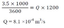
MassFlowraterequired=3to3.5tonnesperhour
Densityofraisin =1200kg/m³
Lengthofvibratingsieve=2.9m
Widthofvibratingsieve =0.6m
Nowforsizertheraisinbysize,eachofraisinsshould comeincontactwithvibratingsieve.
Therefore,Averagethicknessofraisinlayeroversieve(t) =averagethicknessofsingleraisin=0.005m Where, m=ρ×Q
m=massflowrateofraisinoverthevibratingsieveinkg/s Q=dischargeofraisinfromthevibratingsieveinm³/s ρ=densityofraisininkg/m³
K2=factortoconsidertheeffectofdepthofbedofbulk K3=factortotakeintoaccounttheamountoffinesinthe bulkmaterial
K4=factortoconsidereffectofslopeofthetroughonthe averageflowvelocity η =efficiencyoftransport β=throwangleindegrees
β , η , K1 , K2 , K3,
Theusualrangeofthrowangleβ,adopted forvibratoryconveyoris200to550Forthis system,β=250isassumed
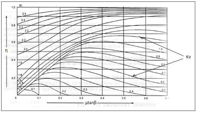
Figure2showsgraphofefficiencyoftransportagainst µtanβ
Q=A×V Where,
Q=dischargeofraisinfromthevibratingsieveinm³/s
A=cross sectionalareaofraisinlayeronsieveinm²
V=transportvelocityofraisinoverthevibratingsievein m/s
8.1×10 4=0.6×0.005×V
V=0.27m/s
Averagetransportvelocityofsolidalongthetroughis givenby
V=η×(2Пn/60)×A×cosβ×K1×K2×K3×K4…eqn.(1) Where,
V=averagetransportvelocityofsolidalongtroughin m/s
n=speedofmotorinrpm
A=amplitudeofvibrationinmm
K1=materialfactor
Fig – 2: GraphofEfficiencyofTransportagainstµtanβ
Forthissystem, β=250andµ=Co efficientoffrictionbetweenraisinand sieve=0.1(assumed) µtanβ=0.05
Formostofconveyor’svalueofthrowfactor(Kv)lies between1.5to3FromFigure2, η=0.85 K1isthematerialfactorwhichistobedeterminedby experimentationandmayvaryfrom0.85to1.1. Forthissystem,assumeK1=0.85(assumed)
Figure3showsgraphofK2againstbeddepth.K2isthefactor to consider the effect of depth of bed of bulk material on trough.Thevalueofthisfactorvariesfromunityforsmall depthto0.7for300mmdepthofbed.
2022, IRJET | Impact Factor value: 7.529 | ISO 9001:2008 Certified Journal
International Research Journal of Engineering and Technology (IRJET) e ISSN: 2395 0056
Volume: 09 Issue: 06 | Jun 2022 www.irjet.net p ISSN: 2395 0072
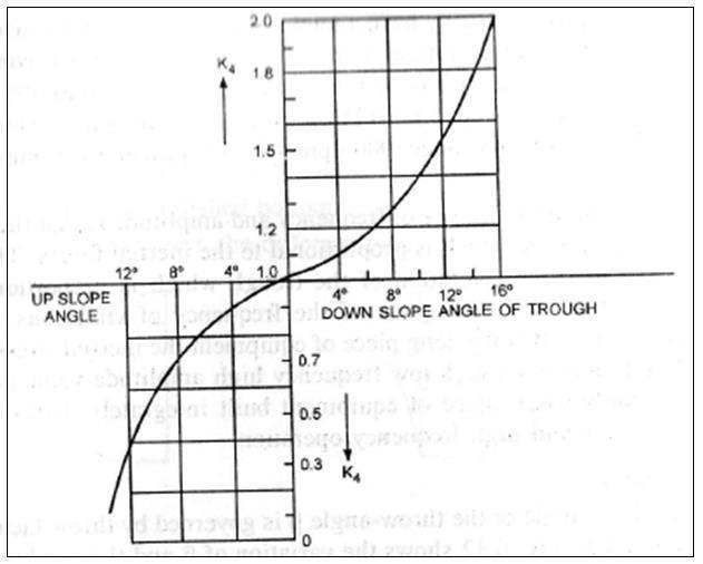
Figure 5 shows graph of K4 against slope angle. K4 is the factor to consider the effect of slope of the trough on the average flow velocity. The value is unity for horizontal conveying for upward conveying slope of about 100, the value of K4 is 0.6. The value decreases rapidly for steeper slope.
Forthissystem,beddepthis5mmandthereforefrom graphvalueofk2=0.95
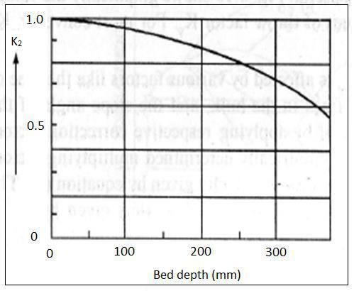
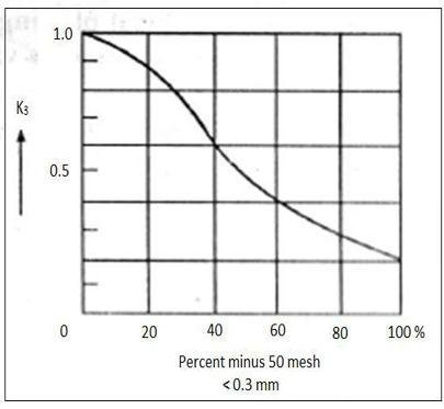
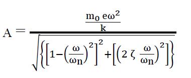
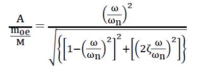
Figure4showsgraphofK3againstpercentminus50mesh. K3 is the factor to take into account the amount of fines particlesinthebulk material.Ifthebulk material contains 20%offineparticleslessthan0.3mm(50mesh),thefactoris 0.85.Ifthebulkcontains60%fineparticleslessthan0.3mm, thefactoris0.4.
Forthissystem,sieveishorizontalandhence, K4=1, Now,forsystemofvibratingsieve, K1=0.85,K2=0.95,K3=1,K4=1,=0.85,n=1440, β=25ºSubstitutingallthesevaluesineqn.(1), 0.27=0.85×(2П×1440/60)×A×cos25×0.85×0.95×1×1 A=2.9mm
Responseofarotatingunbalancesystemisgivenby, Where,
A =amplitudeofvibrationinmeter =unbalancemassinKg
e =eccentricityofunbalancemassinmeter M =massoftotalsysteminKg
Forthissystemparticlesareraisinswiththicknessgreater than0.3mmhencevalueofk3is1.
International Research Journal of Engineering and Technology (IRJET) e ISSN: 2395 0056
Volume: 09 Issue: 06 | Jun 2022 www.irjet.net p ISSN: 2395 0072
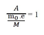
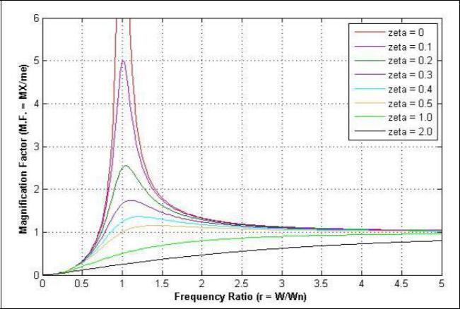
Figure6showsFrequencyResponseofsystemsubjectedto centrifugal force type excitation. In this figure it has been shown that magnification factor becomes unity when frequencyratioisgreaterthan4
Fig 6: FrequencyResponseofSystemSubjectedto Centrifugal
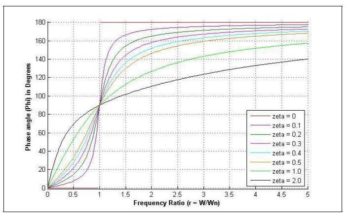
Figure 7 shows phase response of system subjected to centrifugalForcetypeexcitation.Foroursystemfrequency ratio is greater than 4 so phase angle should be greater than120°
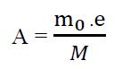
Where, A =amplitudeofvibrationinmeter mo=unbalancemassinKg e =eccentricityofunbalancemassinmeter M=massoftotalsysteminKg mo.e=A.M …..eqn.(2)
M Massoftotalsystemisgivenby, M=MassofVibratingsieve+massofraisinsonsieve M=174+ρ.V
Where, ρ=densityofraisininkg/m3 V=totalvolumeofraisinovervibratingsieveinm3 Now,M=174+1200×2.9×0.6×0.005=183Kg Substitutingthisvalueineqn.(2), =2.9×10 3×183 =0.531Kg m Unbalanceforcerequired =0.531×(2.π.1440/60)2
=12076N
Inthisraisingradingmachinewhenraisinanddebriscomes out from feeder it spreads all over width of sieve. So it is required to give only forward motion to them. For that purposesieveshouldvibratealongitslengthandmovement alongitswidthiscompletelyrestricted.Torestrictmovement ofsievealongitswidth,twomotorsshouldbeselectedwhich will rotate in opposite direction in order to balance horizontalcomponentofunbalanceforce.Hence,raisinswill getonlyforwardmovementonsievealongthelengthofsieve Totalmassmomentrequired=0.531Kg-m
Forsinglemotormassmomentrequired=0.265Kg-m For 0.265 Kg-m moment following motor is selected from Wuergescatalogueofvibratorymotors
Here,N=1440rpmsothisishighspeedmachine Forhigh speedmachine,
Model =H V12/4 301.5 Synchronousspeed =1440 Centrifugalforce =6822 Workingmoment =0.3kg m Nominalcurrent =1.43to0.83A Power =746W Mass =18.8Kg
International Research Journal of Engineering and Technology (IRJET) e ISSN: 2395 0056
Motorsaremountedsuchthattheresultantunbalanceforce willactatthecenterofsieve.Forthismachinemotorsare mountedat bottom ofsieveata distance of600mm from backside of sieve. The motors are mounted such that the maximumunbalanceforceactsonthesieveat250.Forthat purposefoundationofmotorisweldedtosieveatanangleof 650 .
Comparison after changing vibration method by adding propervibratormotoranditsposition
Parameter Before modification After modification
Mass flow rate of raisin 1.75tonnes/hour 3.2tonnes/hour
Inthiswaymodifiedraisinsortingmachineiseffectiveby selecting the proper vibrator motor and selecting proper unbalanceweight.Onemoreadvantageobservedthatdueto thismodificationunskilledworkercanoperatethemachine easily.Thismachinecanbeusedforotherproductsalsolike cashewnuts,groundnuts&somebeansbutbychangingthe sieves.Fromaboveallobservations&improvedmassflow rate of raisin it proves that instead of old eccentrically connectedpullyandbeltarrangement,vibratorymechanism iseffective.
ACKNOWLEDGEMENT (Optional)
Theauthorscanacknowledgeanyperson/authoritiesinthis section.Thisisnotmandatory.
[1] Sangali Grapes Processing, Marketing and reaserch Limited, Gat. no.1952, Subhash nagar, Tal. Miraj, Dist. Sangali,Maharashtra
[2] Differences Technique”, Development of a working Model power Technology. Ambrosio Ugri M.C.B and TarantoO.P,(2006)
[3] Rao, A. V. R., Prakash, C. H. B., and Raju, G. H. T, “Selection of vibratory motors for vibrating feeder by analyticalapproachformaterialhandlingplants”
[4] Narendra V.G, “Quality Inspection and Grading of AgriculturalandFoodProductsbyComputerVision A Review”,ISSN:0975 8887,Vol2,Issue1,2010,pp.43 78.
[5] GeorgeM,“MultipleFruitandVegetableSortingSystem UsingMachineVision”,ISSN:0976 4860,Vol6,Issue1, 2015,pp.1 4
[6] V.P.Singh, “Mechanical Vibration”, Dhanpat Rai Co.pvt ltd.,ISBN13:5551234002564,Vol1,2016,pp.200 240.
[7] Ref:http://www.wuerges.de/
[8] Ref:https://elteco.dk/wp content/uploads/2014/08/W%C3%BCrges katalog.pdf
Volume: 09 Issue: 06 | Jun 2022 www.irjet.net p ISSN: 2395 0072 © 2022, IRJET | Impact Factor value: 7.529 | ISO 9001:2008 Certified Journal