International Research Journal of Engineering and Technology (IRJET) e ISSN: 2395 0056

Volume: 09 Issue: 06 | Jun 2022 www.irjet.net p ISSN: 2395 0072
International Research Journal of Engineering and Technology (IRJET) e ISSN: 2395 0056
Volume: 09 Issue: 06 | Jun 2022 www.irjet.net p ISSN: 2395 0072
Raj1,Bennet Kuriakose 2
1Mtech student, Dept. of civil engineering, St Joseph’s College of Engineering and Technology, Palai, Kerala, India
2 Associate Professor, Dept. of civil engineering, St Joseph’s College of Engineering and Technology, Palai, Kerala, India ***
Abstract When it comes to physical and mechanical characteristics, steel is an excellent building material. By utilizing structural elements with relatively small cross sections, large spans and great heights can be covered. Considering the flexibility and slenderness of these girders, space stability of the whole bearing structure must also be addressed because of their flexibility and slenderness. Traditionally, spatial stability is created by bracings, which serve as a conduit for horizontal forces to be transmitted to the ground and to the foundations. In coordination with the main structure, it can behave as a diaphragm and contribute toitsspatialstability.Thispaperaimstostudyallthefeatures of stressed skin behavior of steel façade frame under varying structural conditions. Conclusions, recommendations, and diagrams provided in this study may be used to guide the application of the "stressed skin design concept" to the real world. The goal here is specifically to optimize fastener number, sheet profile height, height to length ratio of façade frames, and bearing capacity using FEA. All the studies concluded that the introduction of stressed skin behavior of steel façade frame can increase the strength of the structure.
Key Words: Stressed skin behavior, steel façade frame, fasteners,cladding,spatialstability,diaphragm.
Differenttypesofbracingsareusedintraditionalsteelframe constructionstostabilisetheprimarybearingstructurein space, retain the planned geometry and shape, and limit horizontal displacements of the slender elements. The "stressed skin design," on the other hand, stabilises the frame structure because the wall and roof cladding have significantin planestiffness.Asaresult,thecladdinghasthe abilitytoacceptandtransferhorizontalforcesoperatingon thestructurewhilealsoprovidingspatialstability.However, putting this concept into action is challenging due to the difficulty in determining the stiffness of various types of corrugatedsheetsusedascladding,aswellasthestiffnessof theconnectionsbetweenthecladdingandalsothebearing steelframework.Theshearordiaphragmpanelisasection ofthesheardiaphragmmadeupofoneormorecorrugated sheeting separated by structural elements. European standards (EUROCODE EN 1993 1 3 2006) and steel structural design recommendations only address this conceptinbroadterms(ECCS1995).Stressedskindesignis quitepossible,anditproducesresultsthatarecomparableto
or better than braced skin design in terms of stress and deformationofthestructure[1,2]
Inreality,whetherornotthediaphragmeffectisconsidered, itisalwaysthereinabuilding.Economicstudiesconducted inEuropebyorganizationssuchastheEuropeanConvention forConstructionalSteelwork(ECCS)ortheConstructional Steel Research and Development Organization (CONSTRADO,1976)revealedsavingsofupto10%ofthe totalcostofthesteelstructurewhenthediaphragmeffect was taken into account in the design. The fundamental function of roof and wall cladding systems is to keep the structure dry and airtight, while the diaphragm effect transformsthemintomajorstructuralcomponents[5]
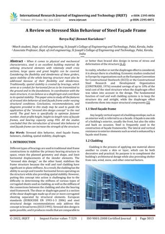
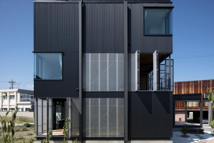
Anylargelyverticalaspectofabuildingenvelope,suchas anexteriorwall,isreferredtoasafacade.Afaçadeisoneside ofabuilding'sexterior,usuallythefront,butalsothesides and back on occasion. Steel is frequently used in the constructionoffaçadeframeworks.Thelateralandvertical resistancetoexteriorelementssuchaswindisenhancedbya façadesteelframe.
Cladding is the process of applying one material above another to create a skin or layer, which can be both decorativeand practical.Itspurpose isto compliment the building'sarchitecturaldesignwhilealsoprovidingshelter fromrain,wind,snow,andotherexternalfactors.
International Research Journal of Engineering and Technology (IRJET) e ISSN: 2395 0056
ISSN: 2395 0072
shear diaphragm, profiledsteel sheeting is highly effective whenusedasroofsheetingordecking,floordecking,orside cladding[3,4].Thebenefitsofstressedskindesignare:
•Calculatedframestressesanddeformationsaretypically substantiallylowerthanbareframestressesanddeflections.
•Stressesanddeflectionscalculatedandobservedagree, makingthedesignmorerealistic.
•Bracingintheroofplaneisremovedortheframesizeis lowered.
•Bydiaphragmaction,stressedskinstructuresutilisethe claddingtowithstandlateralload.
The stressed skin idea has been thoroughly confirmed, based on the fact that the façade and roof cladding of a building with a steel bearing structure have significant in planestiffness,canreceiveandtransmitlateralforcesacting onthebuilding,andofferstructuralstabilityofthestructure. Wedeterminedthatthecladdingcontributedtotheoverall stiffnessoftheentirefaçadeframe,aswellastheprominent stressed skin behavior, by comparing the findings of the framewithoutcladdingandthecladdedframes.Thenumber andgaugeoffasteningdevicesdeterminethestrengthand deformability of the investigated façade steel structure, confirmingearlierfindings.Fasteningofthecladdingtothe steel frame in troughs is along horizontal direction (connectionstothebeams)ratherthantheverticaldirection (connectionstothecolumns)isthedominantinfluence.The process of horizontal force transfer from the frame to the cladding, which occurs primarily through shear of the fasteningmechanismsbetweenthecladdingandtheframe beam,ratherthantheframecolumn,isthereasonforthis.As aresult,theresultsoftheanalysesmaybeusedtoidentify theappropriatenumberandgaugeoffasteningdevices.
Thecladdingcanoperateasadiaphragmandcontribute tothespatialstabilityoftheprimarystructure,enablingthe so calledstressedskindesignconcepttobeimplemented.In other words, the resistance and stiffness of frames are influencedbytheresistanceandstiffnessofroofing,flooring, andsidecladdingpanels.Asaresult,suchpanelsarereferred to as "shear diaphragms" or "simply diaphragms", in the Europe,theyarereferredtoas"stressedskindesign".Asa
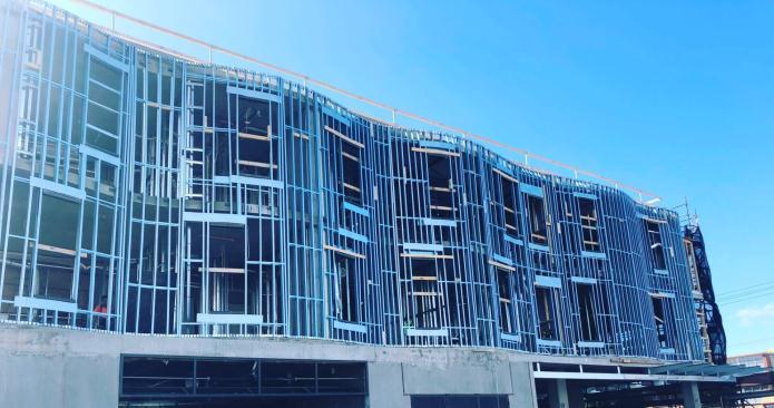
Fig 3:Differentfasteningpositions
International Research Journal of Engineering and Technology (IRJET) e ISSN: 2395 0056
Volume: 09 Issue: 06 | Jun 2022 www.irjet.net p ISSN: 2395 0072
The fastening systems, frame dimensions, type of cladding, and other factors all influence the strength and deformabilityofthestressedskindesignoftheinvestigated façadesteelframe.
In terms of load carrying capacity, the shear resistanceofroofpanelsisdeterminedbythecapacityofthe seamfasteners,thekindandthicknessofthesheeting,and thesidefastening.Fromtwo sidedfasteningstofour sided fastenings,theshearcapabilitycanincreasefourfold[5].
Asummaryoftheload carryingcapacitiesofpanels is provided in table 1. The proportional limit in each configurationisindicatedbythe"Linearrange"column;asa result, the previously mentioned flexibility values can be assureduntiltheseloadlimitationsaremet.Ingeneral,the two skindesignswithnarrowertrapezoidalsheetprofiles had the higher load carrying capacity values. In single skinned systems, using a lower trapezoidal sheet profile (LTP20)increasedload carryingcapacityby30%overusing a larger trapezoidal sheet profile (LTP30) (LTP45). The reason for this could be related to the quantity of fixings available,astheformprofileofLTP20sheetingisintended to have much more corrugations than LTP45 sheeting, allowingformorefixingstobeusedonLTP20sheetsthanon LTP45sheets.Thenumberoffixeshasasignificantimpact on behaviour: reducing the number of fastenings by 50% results in a 16 36% reduction in load carrying capacity. Purlinsizeandthicknessareincreasedby10 40%toboost loadcarryingability[3].
Table 1: Measuredloadcarryingcapacities Tes t No.
5 11
Alternate Single 9.21 11.96 12 Two skin 16.82 22.35 13 Z300/2. 0 LTP20/0. 5 Every Single 17.71 22.41 14
Alternate Single 12.85 16.91 15 Two skin 24.75 28.83 16 LTP45/0. 5 Every Single 14.22 16.15 17 Alternate Single 9.82 12.21 18 Two skin 18.85 22.87
AsillustratedinFig.4(a)and(b),fatiguefailurescreated twocommontypesoffracturepatterns:creaseandstartype. Cracksoriginatingatcreasepointsawayfromthefasteners hole and cracks originating at the screw hole are the two typesofcreaseandstarcrackpatterns[6]
Purlins Trapezoi dal sheeting
Fixing number in troughs
Sheetin g Linea r range (kN)
Load carryin g capacit y(kN) 1 Z200/1. 5 LTP20/0. 5 Every Single 10.22 19.04 2 Alternate Single 7.45 11.52 3 Two skin 17.23 22.02 4 LTP45/0. 5 Every Single 7.81 12.69 5 Alternate Single 7.22 9.71 6 Two skin 11.96 17.58 7 Z250/2. 0 LTP20/0. 5 Every Single 18.25 23.65 8 Alternate Single 12.45 17.41 9 Two skin 25.67 33.03 10 LTP45/0. Every Single 13.66 15.56
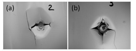
Mahendran [7] made a similar observation using lineloadtestloadingsystems.AccordingtoHenderson[8], thecreasefracturesaredividedintotwopatterns:'H'and'T.'
For Pmax, Fig. 6 illustrates the number of cycles duringwhichacrackisinitiatedandthenumberofcycles during which it fails. Fig 6 also depicts the crack types at failureforeachtest,whichcanbelinkedtotheloadratioR and ultimate load per cycle as indicated in Fig 5. When a crack larger than 1.0 mm is discovered, it is called crack initiation. The numbers of cycles for commencement and failure in the material being tested may not be the same. Theydenotethenumberofcyclesrequiredfortheinitiation andfailureofanyofthefour"completelyloaded"screws.For creasetypecracks,acrackbeginsearlierinthecyclecounts, with cracks occurring at the crease points away from the screwhead.Thesefractureshaveahigherstresseachcycle than the star cracks that occur beneath the screw head. Furthermore, failure from crease type cracks necessitates much longer cracks with correspondingly quicker developmentrates[6]
International Research Journal of Engineering and Technology (IRJET) e ISSN: 2395 0056
Fig -5: Peakpressurewithnumbersofcyclestofailure
that avoid the use ofseam fasteners andare often usedin everydaybuildingthroughoutEurope.Thepresentliterature examines[9]andevaluatestheshearflexibilitydata,including a comparison of test and computed results. The stiffening impactoftheanalysednonstandarddiaphragmsisshownto beunderestimatedbytheECCSformulas.Thediscrepancies rangefrom3%to100%,withconsiderablescattering.The usefulnessofpresentformulaeislimitedtostandardsetups, andtheprimarygoalofthisstudyistoexpandthesphereof applicabilityofcurrentformulaesothattheycanbeusedin nonstandardsituations.Moreresearchisneededtoidentify the variables that influence the shear stiffness of non standarddiaphragmconfigurations.Theeffectofdiaphragm heightandfixingnumber,aswellasstructuralcomponents (purlins, bracing, and sheeting) on shear flexibility, are discussedfurther.
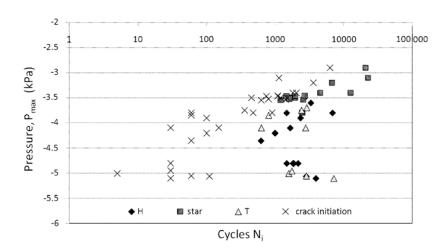
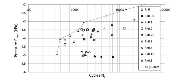
Fig 6: Numberofcyclestocrackinitiationandtofailure forstarandcrease(‘H’and‘T’)typecracks.
Creasepointsformedaroundtheedgesofthedistorted crests under loads greater than the corrugated cladding's local plastic deformation (LPD) strength. Cracks began at these crease locations and grew outwards, forming a 'X' shapelongitudinallyandtransversely[6]
Undertheflexiblesealthatfitsbetweentheunderneathof thescrewheadandthecladdingasaweatherwraponthe screwholes,starcracksappearinthecladdingatthescrew hole.Duringthestaticloadingexperiments,cracksoccurred at lower pressures than the pressures recorded for local plasticdeformation[6].
Afurtherstudyprogrammeisintendedtoimproveand extendthecurrentdesigntechniques,basedonananalysisof theavailableresearchfindingsanddesignrecommendations on stressed skin effect, as well as preliminary numerical calculations.Theresearchprogram'spurposeistoinvestigate thestiffeningeffectofnonstandarddiaphragmconfigurations
Theimpactofsectionsizeandthenumberoffastenerson shearflexibilityisexaminedindepth.Infullycladinstances, raisingthesectionheightofpurlinsincreasesshearflexibility by6 109%.Inthosecaseswherenobracingswereused,a smaller rise of 1 55 % wasrecorded. Acontrasting trend was observed in roof cladded and braced configurations: increasingpurlinheightleadstoanincreaseinflexibilityof 11 44 %. In some circumstances, removing the bracing allows for more flexibility. The flexibility of a trapezoidal sectionincreasesbyupto53%whentheheightofthesection isincreased.Thisconclusiondoesnotapplytodiaphragms that are only found in the roof. Shear flexibility is mostly influencedbytheamountoffixes.Whenusinghighersheets, theflexibilityisreducedby17 40%,implyingthatdoublethe numberoffixesisused.Byusingsmallersheetheights,this rangemightvarybetween2%and30%[10,14].
Whencomparingtheeffectofpurlinsonthestructure's shearflexibility,itmaybeconcludedthatroofpurlinsstiffen thebuildingmore(2 6%)thanwallpurlins.Theuseofroof bracingincreaseshallstiffnessby2 3times,whereastheuse of roof and wall bracing makes the structure 8 10 times stiffer. This demonstrates that bracing has a significant impact on the shear rigidity of the structure. The use of internalandexternalcladdingreducesshearflexibilityby40 78%,demonstratingthenon negligiblestiffeningimpactof steelcladding.Internalcladdinghasaminorimpactonshear flexibilityascomparedtoexternalsheets.Atmodestpurlin profiledcases,thisvaluedecreasesby1%to5%,whereasat highprofiledcases,itdecreasesby1 15%.Theresultsofthe diaphragm effect show that the stiffening impact of diaphragmsiscomparabletothestiffeningeffectofbracingin nonstandardcircumstances.
Thefindingsindicatedthattheinfluenceofpurlinsinboth the wall and the roof reduces shear flexibility by 17 40%.
Volume: 09 Issue: 06 | Jun 2022 www.irjet.net p ISSN: 2395 0072 © 2022, IRJET | Impact Factor value: 7.529 | ISO 9001:2008 Certified Journal
International Research Journal of Engineering and Technology (IRJET) e ISSN: 2395 0056
Volume: 09 Issue: 06 | Jun 2022 www.irjet.net p ISSN: 2395 0072
The installation of wall covering reduces flexibility by between24and87%.Claddingplusbracingofthestructure reducesflexibilityby27 86%,whilebracingalonereduces flexibilityby57 86%inuncladframes.Theinfluenceofinner claddingonflexibilityisreducedby23 75%[10,14]
The effects of varying overhang lengths (150 mm and300mm)onthepull throughcapabilityofcorrugated andtrapezoidroofcladdingswereexploredbyNasirahet.al. Ahydraulictestingmachinewasusedtoconductaneweasy testprocedureusingsingle spancladdingunderstaticuplift pressure. The pull through capacity of corrugated roof claddingwasgreaterthanthatoftrapezoidalroofcladding, according to the findings. Furthermore, as the overhang length was extended, the steel cladding's pull through capacity decreased for both cladding profiles. Localized dimplingfailureofcorrugatedcladdingandcross sectional deformationoftrapezoidalroofcladdingwereobservedasa resultofthis study.Inconclusion,increased roofcladding lengthdecreasedpull throughcapacityandappliedloadfor bothcladdingprofiles.
Forthe150mmand300mmoverhanglengths,respectively, corrugated roof cladding produced an average maximum fastenerreactionforceof1.47kNand0.46kN,aswellasan average maximum deflection of 80.25 mm and 58.75 mm. Thefastenerresponseforceofthecorrugatedroofcladding with150mmand300mmoverhandlengthwas53%and72 %fortrapezoidalroofcladding,respectively.Thedeflection of trapezoidal roof cladding with 150 mm and 300 mm overhang lengths, on the other hand, was 23% and 38% larger than that of corrugated roof cladding, respectively. Under static wind uplift stress, corrugated roof claddings hadlocaldimplingfailure,whereastrapezoidalroofcladding experienced cross sectional deformation of the discretely fastenedroofing.Thelengthoftheoverhang,theamountof uplift loading, and the amount of deflection all have a relationship. Increased overhang length resulted in a reducedupliftforcebeneaththeoverhangingroofaswellas lesserdeflectionforbothcladdingprofiles.Corrugatedroof claddinghadahigherfastenerreactionforce(pull through capacity)andmaximumappliedloadthantrapezoidalroof cladding.Thedeflectionoftrapezoidalroofcladding,onthe otherhand,isgreaterthanthatofcorrugatedroofcladding. With increasing roof cladding length for both cladding profiles,themaximumfastenerresponseforceandapplied loaddecreased[12].
One of the advantages of using the stressed skin designisthatitiscosteffective.Thestressedskinstructure was found to be 8 15 % less expensive than the braced structureinthisstudy[2].Whencomparedtoadesignthat
ignoresstressed skinaction,thematerialcostoftheinternal framecanbeloweredbyasmuchas53%forabuildingwith two internal frames [13]. The findings of the least cost optimisationshowthatwhenstressed skinactivityistaken intoconsideration,thecostoftheinternalframefor"square shaped" buildings can be cut in half. It's important to remember that this is a least cost optimization, not a minimumweightoptimization[11].
Theinitialstagesofstressedskindesigncoincided with a massive, government led construction boom that included prominent schools and hospitals. Many of these weremadewiththehelpofsystems,andalotofeffortwent intoincorporatingstressedskindesignintothem.Thiswas donenotsimplytosavemoneyoncrossbracing,butalsoto make the system easier to understand in terms of design calculations and component count. Standard diaphragm designs might be employed without the requirement for complexcalculationsthankstodesigntables.Thecontractor must then select his own decking profile and fastener specifications and demonstrate that they meet the performance requirements, which include the load in the roof plane that must be resisted and stressed skin design. Thealuminiumlinertraysintheroofsofthestandsatboth theMillenniumStadiuminManchesterandthenewstadium forArsenalFootballClubaretworecentsignificantinstances ofthistechnology[15].
Thefasteningsystems,framedimensions,typeof cladding, and other factors all influence the strength and deformabilityofthestressedskindesignoftheinvestigated façadesteel frame.Stressed skindesignseemstobequite possible, and it produces satisfactory results in terms of structural stress and deformation, equal to or better than braced design. We found that the cladding contributed significantly to the overall stiffness of the entire façade frame,aswellastheprominentstressedskinbehaviour,by comparingthefindingsof theframe withoutcladdingand thecladdedframes.Thefindingsofthisstudy,aswellasthe conclusions,recommendations,andguidingillustrations,can be used as design guides when using the "stressed skin designconcept."Thisreferstothenumberoffastenersused, thethicknessofthesheets,theheight to lengthratioofthe façadeframe,andthebearingcapacityofsuchframes.
[1] Vacev,T.,Zoric,A.,Rankovic,S.,Milic,M.,Paunovic,S., Nesovic , I. , “Analysis of Stressed Skin Behaviour of a Steel Façade Frame Under Varying Structural Conditions,InternationalJournalofSteelStructures,Dec 2019. doi: https://doi.org/10.1007/s13296 020 00425 2
2022, IRJET | Impact Factor value: 7.529 | ISO 9001:2008 Certified Journal |
International Research Journal of Engineering and Technology (IRJET) e ISSN: 2395 0056
Volume: 09 Issue: 06 | Jun 2022 www.irjet.net p ISSN: 2395 0072
[2] Vacev,,T.,Zoric,A.,Rankovic,S.,Milic,M.,Paunovic,S., Nesovic,I.,“StressedSkinDesignVersusBracedFrame Design Through Efficient Numerical Modelling ˮ, InternationalJournalofSteelStructures,Nov2019.doi: https://doi.org/10.1007/s13296 020 00352 2
[3] Lendvai,A.andJo,A.L,“Improvementofstressedskin designprocedurebasedonexperimentalandnumerical simulationsˮ,JournalofConstructionalSteelResearch, vol.168,Nov 2019.doi: https://doi.org/10.1016/j.jcsr.2019.105874
[4] Gryniewicz,M.,Roberts,M.J.,Davies,J.M.,“Testingand analysisofa full scalesteel framedbuildingincluding the consideration of structure cladding interaction ˮ , Journal of Constructional Steel Research, vol.181, Feb 2021.doi:https://doi.org/10.1016/j.jcsr.2021.106611
[5] Z.s.Nagy,A.Pop,I.Moiș,R.Ballok,“StressedSkinEffect ontheElasticBucklingofPitchedRoofPortalFramesˮ, Structures,May2016.
[6] Henderson,D.J.andGingerJ.D.,“Responseofpierced fixedcorrugatedsteelroofingsystemssubjectedtowind loads ˮ, Engineering Structures, vol.33, Aug 2011,pp 3290 3298.doi: https://doi.org/10.1016/j.engstruct.2011.08.020
[7] Mahendran, M., “Fatigue behaviour of corrugated roofing under cyclic wind loading ˮ, Civil Engineering TransactionsIEAust;1990.
[8] Henderson DJ., “Response of pierced fixed metal roof cladding to fluctuating wind loads ˮ, Ph.D. thesis. Townsville(Australia)JamesCookUniversity;2010
[9] Lendvai,A.,Jo,A.L,Dunai,L.,“Experimentalfull scale tests on steel portal frames for development of diaphragmaction PartIexperimentalresultsˮ,Thin WalledStructures,inpress.
[10] Lendvai,A.andJo,A.L,“Experimentalfull scaletestson steelportalframesfordevelopmentofdiaphragmaction Part II Effect of structural components on shear flexibilityˮ,Thin WalledStructures,inpress.
[11] Wrzesien, A.M., Phan, D.T., Lim, J.B.P., Lau, H., Hajirasouliha,I.,Tan,C.S.,“EffectofStressed skinAction on Optimal Design of Cold formed Steel Square And Rectangular shaped Portal Frame Buildings ˮ, InternationalJournalofSteelStructures,vol.16(2),June 2016,pp299 307.
[12] Siron, N., Majid, T.A., Zaini, S.S., “Experimental investigation on the effects of overhang length variationsofsteelroofcladdingunderupliftpressureˮ, Structures, vol. 32, April 2021, pp 2032 2041.doi: https://doi.org/10.1016/j.istruc.2021.04.007
[13] Phan,D.T.,Lim,J.B.P.,Tanyimboh,T.T.,Wrzesien,A.M., Sha,W.,Lawson,R.M.,“Optimaldesignofcold formed steelportalframesforstressed skinactionusinggenetic algorithmˮ,EngineeringStructures,vol.93,Feb2015,pp 36
49.doi:http://dx.doi.org/10.1016/j.engstruct.2015.02.0 37
[14] Wrzesien,A.M.,Lim,J.B.P.,Xu,Y.,MacLeod,I.A.,Lawson, R.M.,“Effectofstressedskinactiononthebehaviourof cold formed steelportal frames ˮ, Engineering Structures, vol.105, Oct 2015, pp 123 136. doi: http://dx.doi.org/10.1016/j.engstruct.2015.09.026.
[15] Davies, M.J., “Developments in stressed skin design ˮ, Thin Walled Structures,vol.44 , 2006, pp 1250 1260. doi:https://doi.org/10.1016/j.tws.2007.01.002
2022, IRJET | Impact Factor value: 7.529 | ISO 9001:2008 Certified Journal