Comparative Study Between Cross Flow Air To Air Plate Fin Heat Exchanger With Triangular

 Mansoor Imtiyaz1 , Shilpa Mondkar²
1Student, Dept. of Mechanical Engineering, Pillai College of Engineering, Maharashtra, India 2Asst. Professor, Dept. of Mechanical Engineering, Pillai College of Engineering, Maharashtra, India ***
Abstract Indoor Air Quality (IAQ) is a term which we get to hear a lot after the commencement of the coronavirus pandemic. Heat recovery ventilation (HRV) can play a very important role in this. The fresh air from the ambient is separated from the stale air exhausted from the indoor facilities. Due to this the fresh air is not contaminatedby the moisture, dust, pathogens, particulate matters, pollutants, smoke, smell etc. which is exhausted directly from the indoors and only heat transfer takes place further decreasing the load on HVAC systems. Computational fluid dynamics analysis between conventional plate fin heat exchanger model with triangular extended surfaces and proposed perforated model was performed and the comparative characteristics where studied. In order to maximize the parameter such as thermal effectiveness, recovered heat, outlet temperatures, Taguchi analysis was implemented using the L9 orthogonal array. The design variables and levels that would maximize the thermal effectiveness and other factors were plate thickness, velocity offluidandplateheight.
They are further divided into cross, counter and parallel flow [1]
1. INTRODUCTION
HRV also known as the heat recovery air exchangers or Mechanical ventilation heat recovery (MVHR), are equipped with two continuously running fans. The first one expels indoor stale air (consisting of smell, smoke, pollutants, pathogens etc.), and the second one supplies fresh filtered air from the outside. The fresh new air and expelledstaleairnevercomeintocontactwitheachother; the air is not recycled. This technology absorbs heat or cooledenergyandrecyclesit;itdoesnotgenerateit.Itcan recover heat during winter or cool during summer from theexpelledstaleair,andtransfersittothefreshincoming filteredair.InthearticletheHRVtypetobediscussedisa Fixed plate type heat exchanger with extended surfaces (fins).Plate heat exchangers are heat exchangers well known since the 1940's. They can be used as a sensible heat or energy recovery, and are characterized by high effectiveness,compactness,lowweightandmoderatecost.
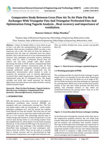
Figure 1: Plate fin heat exchanger exploded diagram
1.1
Working principle of PFHE.
Theworkingprincipleofaplatefinheatexchangerisquite simple.Hereisan example ofcross flow plate finnedheat exchanger. In cross flow the fluids are at an angle of 90°, thetwofluidsinvolvedintheheatexchangeareseparated byapartingsheet.Whichactsastheprimaryheattransfer surface. It has side bars which prevents the fluid from spilling. And extended surfaces or fins which are sandwiched between the parting sheets. They act as the secondaryheattransfersurfaces.
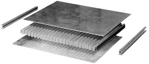
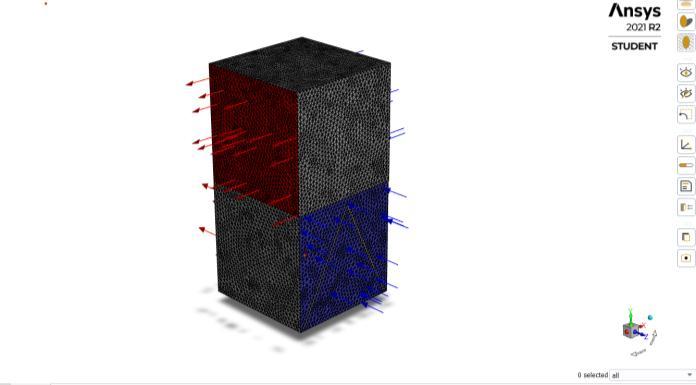
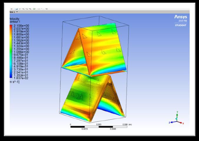
Figure 2: Cross flow plate fin heat exchanger meshing
Asthefluidentersthroughthechannelsoftheinlet,dueto the temperature gradient between the two fluids heat transfertakesplacethroughconvectionbetweenthefluids and the primary and secondary heat transfer surfaces. Thistypeoffixedplateheatexchangershassuperiorityto rest of the heat exchangers because of their compactness. Largeheattransfersurfaceareaperunitvolume(typically 1000 m²/m³). It produces a high overall heat transfer coefficientbecauseoftheheattransferassociatedwiththe narrowpassagesandcorrugatedsurfaces.
Fins And Triangular Perforated Fins And Optimization Using Taguchi Analysis. , Heat recovery and importance of ventilation.Keywords Plate Fin Heat Exchanger, Taguchi Analysis, Heat Recovery Ventilation, Computational Fluid Dynamics, Thermal Effectiveness, Perforations.
International Research Journal of Engineering and Technology (IRJET) e ISSN: 2395 0056
Volume: 09 Issue: 06 | June 2022 www.irjet.net p ISSN: 2395 0072
2.TAGHUCHI ANALYSIS
Table 1:Selected3 levelcontrolparametersandtheir sub levels
LEVELS PLATE THICKNESS (mm)
(mm)
3.1 Preprocessing:
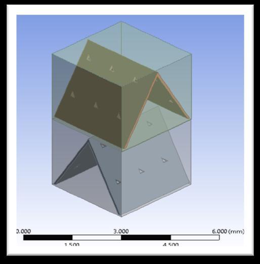
Step 1:ConstructionofGeometry.Thisproblemhasthree geometriesnamely,
1. Freshfluidsection
2. Intermediateplatesection 3. Stalefluidsection
The geometries of given problem are created by using Spaceclaimsoftware. Velocityofthefluid:2m/s Fin’stype:plain
The Taguchi method is used to determine the main (important) parameters that have the greatest impact on the response parameter under study. Instead of changing one factor, each time with this method, all factors are changedatonceaccordingtothedesignarrayandalsothe change of response values according to the selected performance parameter is observed. It is also possible to evaluate several factors with the minimum number of experimentsornumericalsolutionsbyTaguchimethod
Table 2: 9differentdesignednumericalPHEmodels accordingtoTaguchi
Step 2:MeshingtheModel
1. VolumemeshwithPolyhedralandprismlayer
Setting physics of the Problem
Sinceinthisproblemconsistsofthreephases,weneedto select three physics, one for gas, second for liquid and anotherforSOLID.Physicsselectedforthefluids
Three DimensionalFlow.
Constantdensity
SteadyFlow.
Segregatedflowmodel
TURBULENTFLOWwithK Epsilonmodel
The Boundary Conditions
In this problem there is inlet one for cool stream and otherforhotsteam,throughthecrosssectionofcore.Both streams are separated by each other by an intermediate plate and both are velocity inlet type. Similarly, there are two outlets in which are pressure outlet type the cross sectionisgivenassymmetrytypeandremainingarekeep as a wall which are smooth, no slip and adiabatic. The velocity at both the inlet is 2 m/s. the pressure at the outletisoneatmosphere.
3. CFD details and methodology
Freshairtemperature=305k Staleairtemperature=295k.
4. Results
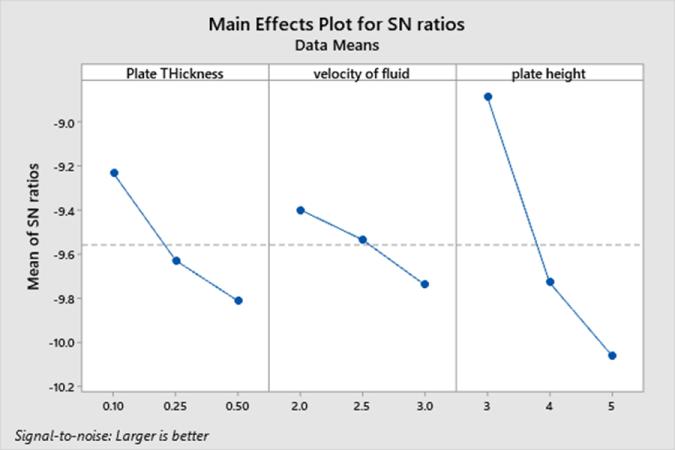
The results of Taguchi obtained are given below. Accordingtothe9modelsmadeandbasedontheTaguchi analysisfromMINITAB2019,themodelwiththecofactors which is 0.10mm plate thickness, 2 m/s velocity of fluid and3mmofplateheight.Andtheresponsetableforsignal tonoiseratioinwhichlargerisbetterwasconsidered,the rank was given in the follo9wing order; A to plate thickness,BtovelocityofthefluidandCtoplateheight.
International Research Journal of Engineering and Technology (IRJET) e ISSN: 2395 0056
Volume: 09 Issue: 06 | June 2022 www.irjet.net p ISSN: 2395 0072
Therefore, according to the fresh air outlet temperatures obtained,theeffectivenesswascalculatedandagainmodel 1resultedinthemaximumthermaleffectiveness.
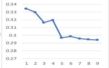
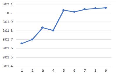
Figure 3: Response table for S/N ratios
Figure 6: Effectiveness curve for 9 Taguchi models.
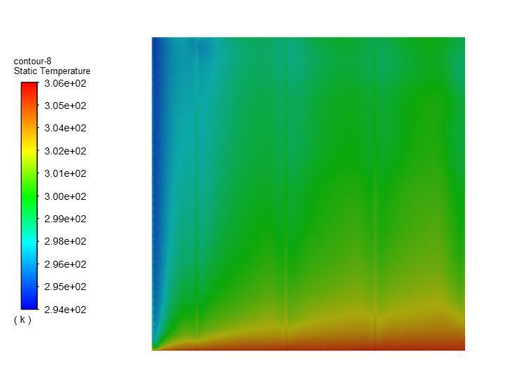
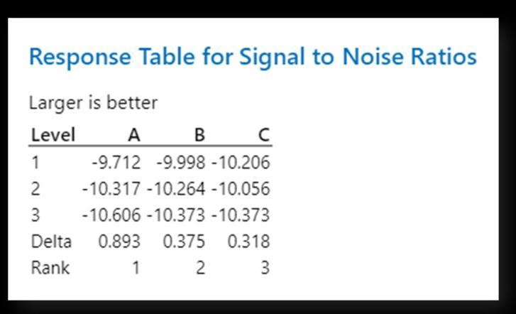
Figure 4: Signal to noise Ratios Plots
The fresh air outlet temperatures obtained for 9 different modelsarerepresented below.Themaximumdecrease in temperature was for the model 1 and the model 7 , 8 ,9 showedsimilardecreasepattern.
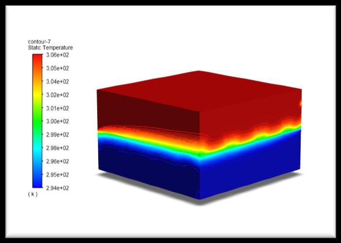
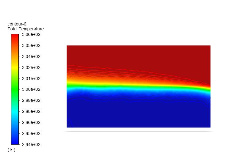
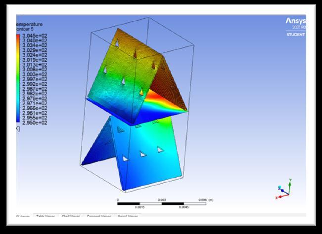
Figure 7: Temperature Contour for the PFHX
Figure 5: Fresh air outlet temperatures for the 9 Taguchi models.
Figure 8:Temperature contour for the intermediate plate
International Research Journal of Engineering and Technology (IRJET) e ISSN: 2395 0056
Volume: 09 Issue: 06 | June 2022 www.irjet.net p ISSN: 2395 0072
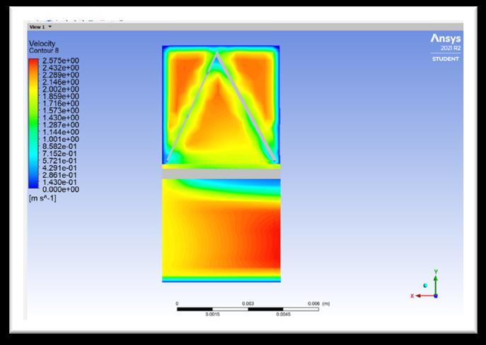
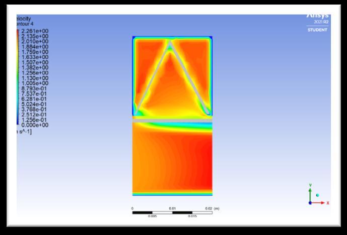
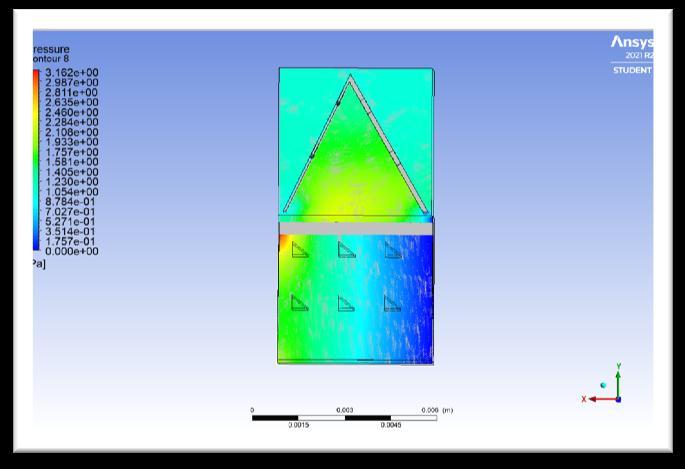
After obtaining results, from Taguchi analysis the model whichgavethehighestthermaleffectivenesswasdesigned andnumericallyverified.Nowinordertofurtheroptimize the design and size , a new model with triangular perforationswasdesignedandCFDANALYSISwascarried onit.Theresultsbelowwerehenceobtained.
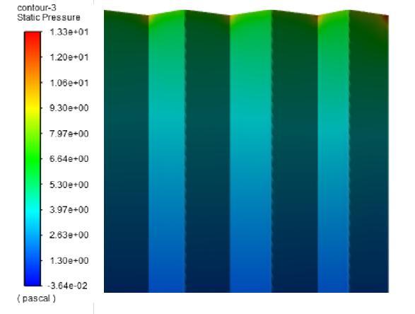
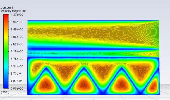
Figure 14: Velocity Contour
International Research Journal of Engineering and Technology (IRJET) e ISSN: 2395 0056
Volume: 09 Issue: 06 | June 2022 www.irjet.net p ISSN: 2395 0072
5.CONCLUSIONS
In this study, a cross flow plate fin heat exchanger with fixedplate,andtriangularfinswithtriangularperforations was designed by using CFD and Taguchi method for maximum Thermal effectiveness. In Taguchi analysis, 3 control parameters each with 3 levels were selected and numerical analysis were derived for designed 9 different 3 dimesionalCFDmodels
Whenoptimal levelsofthe cofactors were used to create design for maximum thermal effectiveness, thermal effectiveness was obtained as 45.73% which is greater thantheconventionalmodelthermaleffectivenessby8to 10%.
By using the optimal levels of factors for the maximum thermal effectiveness, the difference between thermal effectiveness predicted by the Taguchi method (45.7264%) and that obtained from the solution of the new optimum PHE numerical model (53.289%) .the differenceobtainedwaslessthan10%.
the total heat recovered was which was 56.46w(1.354 KW .H/DAY) in the conventional model was increased to 87.93w(2.110KW.H/DAY)inthe proposedmodel. Consideringtheaverageairflowrateis19toto 25m³/H per person. the PFHE can easily serve 4 5 people comfortably.
6. FUTURE SCOPE
2) Zender Swiercz,E.A´ReviewofHeatRecoveryin Ventilation. Energies 2021, 14, 1759. Https://doi.org/10.3390/en14061759|
3) Room Ventilation & Airborne Disease Transmission In A Healthcare Setting Energy UniversityCourseTranscript
4) ENERGY RECOVERY VENTILATION UNDERSTANDING ENERGY WHEELS AND ENERGYRECOVERYVENTILATIONTECHNOLOGY
By: Mark Rabbia, George Dowse Carrier CorporationSyracuse,NewYorkSeptember2000
5) ERICORPORATION
6) Saffa Riffat and Shihao Zhang |Review of Heat RecoveryTechnologiesforBuildingApplications| Energies 2019, 12, 1285; doi:10.3390/en12071285
7) Grosse Gorgemann, A., Hahne, W., and Fiebig, M., 1993, “Influence of Rib Height on Oscillations, Heat Transfer and Pressure Drop in Laminar Channel Flow,” Proceedings of Eurotherm 31, VorticesandHeatTransfer,Bochum,Germany,pp 36 41.
Experimental model could be made tested analyzed and compared with the CFD and numericalresults.
Perforations for porous media can be used and analyzed
8) Masitah,A.R.S.,MardianaIAhmadandY.M.Yatim | Heat Transfer and Effectiveness Analysis of a Cross Flow Heat Exchanger for Potential Energy Recovery Applications in Hot Humid Climate | Masitah, A.R.S. et al. / Energy Research Journal 2015,6(1):7.14DOI:10.3844/erjsp.2015.7.14
Usage of different material such as cellulose, paperthatcanretainmoistureintheapplications ofERVcouldbestudied.
9) Turk, A.J, and Junklan, G.H., 1986, “Heat Transfer Enhancement Downstream of Vortex generators on a Flat Plate,” Proceedings of the Eighth International Heat Transfer Conference, San Francisco,Vol.6,pp.2903 2908
Circular perforations could be design for the fins anditseffectcouldbestudied.
7. REFERENCES
1) Gabriela Elena Vlad, Constantin, Horia Necula, Adrian, Analysis of An Air To Air Heat Exchanger Designed for The Mechanical Ventilation System ofAHouse|U.P.B.Sci.Bull.,SeriesC,Vol.76,Iss.1, 2014
10) SPremkumarD,DMangeshM,LSachinM,KSunil V | Design and Study of Triangular Plate and Fin Heat Exchanger | International Research Journal of Engineering and Technology (IRJET) e ISSN: 2395 0056Volume:05Issue:06|June 201