CONTROL OF HYDRAULIC FORCES ON A SQUARE AND CIRCULAR CYLINDER USING MULTI-ELEMENT SPLITTER PLATE
1,2,3,4
5,
Abstract Vortexsheddingisanoscillatingflowthattakes place when a fluid such as air or water flows past a bluff body. Von Karman vortex shedding is a repeating pattern ofswirlingvorticescaused byvortexshedding.Thevortex regime behind the body has a lower pressure in its core whencomparedtothefreestreamvelocitywhichcreatesa liftforce(FL)andthe pressurefieldatthe rearpart of the bodycreatesdragforce.
The proposed project involves numerical analysis (two dimensional) of vortex structure behind the square and circular cylinder. Splitter plate has considerable effect in stabilizing the transverse flow behind the body by rearranging the vortex street. The current works involves optimizing the splitter plate configuration by using different values of D/H(0, 1, 1.5,2.0)and employing multi element splitter plate. The width of the splitter plate is takenas30mmanditsthicknessas2mmtominimizeflow interaction. Numerical flow visualization is carried out usingtransientsimulationandthenumerical simulationis carried out in ANSYS FLUENT with an inlet condition of Re=1.0×10⁴ taking the gap between the square cylinder and splitter plate and angle of splitter plate as a variable geometric parameter. The project is aimed at numerically investigatingthereductioninliftcoefficient(CL)invarious splitter plate configurations and using the results to evaluatethepotentialbenefitsofemployingmulti element splitterplateconfiguration.
1.INTRODUCTION
This project deals with variation of different hydraulic propertiessuchaspressure,velocityandstreamline.These variations are analyzed in different configurations. These different configurations are arranged with a ratio of diameter/side length and distance between cylinder and splitter plate. The proposed project involves numerical analysis (two dimensional) of vortex structure behind the squareandcircularcylinder.Splitterplatehasconsiderable effectinstabilizingthetransverseflowbehindthebodyby rearranging the vortex street. The current works involves optimizing the splitter plate configuration by using differentvaluesofD/H(0,1,1.5,2.0)andemployingmulti element splitter plate. The width of the splitter plate is takenas30mmanditsthicknessas2mmtominimizeflow
interaction. The project is aimed at numerically investigatingthereductioninliftcoefficient(CL)invarious splitter plate configurations and using the results to evaluatethepotentialbenefitsofemployingmulti element splitterplateconfiguration.
2. Literature review

2.1 reduction of fluid forces and vortex shedding frequency of a circular cylinder using rigid splitter plates.
RezvanAbdiet.al(2017)conductedastudyonreductionof fluid forces and vortex shedding frequency of a circular cylinder using rigid splitter plates. A comprehensive parametric study was performed to identify the optimum arrangement of the plates using the commercial finite element software, Comsol Multiphysics. The results show thatthelocationandthenumberoftheplateshavecrucial effectsonthewakecontrol.
2.2 Active control of the hydraulic forces of a body by a splitter plate.
NorioAraiandMasatomoKomatsu(1991)investigated on activecontrolofthehydraulicforcesofabodybyasplitter plate.The two dimensional incompressible Navier Stokes equation is solved numerically. The interaction between the transverse flow (behind the body) and the splitter has considerable influence on the rearrangementofthe vortex street. With the splitter plate suitably located, the peak of the lift coefficient is reduced to 40% of the isolated body case. Also, the frequency of the variation of the lift coefficient becomes smaller. It is found that there is an optimallocationforthesplitterplate.
2.3 Bifurcation analysis of flow over a rotatable cylinder with a splitter plate.
J. Xu et.al, (1991) conducted a bifurcation analysis of flow over a rotatable cylinder with a splitter plate. The two dimensional, incompressible, unsteady Navier Stokes equations expressed in stream function and vorticity are solvedbyusingafinite differencemethodonanumerically
International Research Journal of Engineering and Technology (IRJET) e ISSN: 2395 0056
Volume: 09 Issue: 06 | June 2022 www.irjet.net p ISSN: 2395 0072
generated, boundary fitted and moving curvilinear coordinatesystem.Detailedstudyoftheflowfieldsuggests that the observed offsetting of the plate are mostly influencedbytheseparationprocessbehindthebody.
2.4 Suppression of vortex shedding of circular cylinder in shallow water by a splitter plate.
Huseyin Akilli et.al, (2005) conducted a study on suppression of vortex shedding of circular cylinder in shallowwaterbyasplitterplate.Theflowbehavioraround a vertical circular cylinder placed in shallow water was controlled by a splitter plate inserted at various locations downstream of the cylinder. The splitter plate has a substantial effect on the suppression of the vortex sheddingforthegapratio(G/D)between0and1.
METHODOLOGY
1. StudyofCFDtools. 2. Literaturereview. 3. ModellingandMeshingoftheconfiguration. 4. Numerical flow visualization of vortex structures withoutsplitterplate. 5. Numerical flow visualization of vortex structures withvarioussplitterplateconfiguration. 6. Theoreticalstudyofvortexstructures. 7. Investigating the influence of multi element splitterplate.
Ansys tools and taken parameters. Sl.no Ansystool Takenas: 1 Typeofflow Transient 2 Steptime 0.025s 3 Timesteps 600 4 Schemeof equations SIMPLE
Table-2.1,Ansystoolsandtakenparameters.
FLUID PROPERTIES
Sl.no Fluid property Assigned value Unit
1 Fluiddensity 1000 Kg/m3 2 Fluidvelocity 10 m/s 3 Kinematic viscosity 0.001 Pa.s 4 Reynold’s number 2*105
Table 2.2,Fluidpropertiestaken. Different configurations used.
Sl.no Diameter (D) (mm)
D/H ratio 1 10 0 0 2 10 20 0.5 3 10 10 1
Distancebetweenbluff bodyandsplitterplate (H)(mm)
Table 3,Configurationsofbluffbodyandsplitter plate.
MESH
Square cylinder
ObjectName Mesh State Solved Display
DisplayStyle BodyColor Defaults PhysicsPreference CFD SolverPreference Fluent Relevance 0 ExportFormat Standard ElementOrder Linear Sizing SizeFunction Curvature RelevanceCenter Coarse SpanAngleCenter Fine
CurvatureNormalAngle Default(18.0°) MinSize Default(1.5958e 004m) MaxFaceSize Default(1.5958e 002m)
GrowthRate Default(1.20)
AutomaticMeshBased On
International Research Journal of Engineering and Technology (IRJET) e ISSN: 2395 0056
Volume: 09 Issue: 06 | June 2022 www.irjet.net p ISSN: 2395 0072
Defeaturing
DefeatureSize Default(7.9789e 005m)
MinimumEdgeLength 1.e 003m
Quality
CheckMeshQuality Yes,Errors
TargetSkewness Default(0.900000)
Smoothing Medium MeshMetric None Inflation
UseAutomaticInflation None
InflationOption SmoothTransition TransitionRatio 0.272
MaximumLayers 2 GrowthRate 1.2
InflationAlgorithm Pre ViewAdvancedOptions No AssemblyMeshing Method None Advanced
Number of CPUs for ParallelPartMeshing ProgramControlled StraightSidedElements
NumberofRetries 0
RigidBodyBehavior DimensionallyReduced MeshMorphing Disabled TriangleSurfaceMesher ProgramControlled TopologyChecking No
UseSheetThicknessfor Pinch No
PinchTolerance Default(1.4362e 004m) GeneratePinchonRefresh No SheetLoopRemoval No Statistics Nodes 50137 Elements 49634 Circular
SolverPreference Fluent Relevance 0
ExportFormat Standard ElementOrder Linear Sizing SizeFunction Curvature RelevanceCenter Coarse SpanAngleCenter Fine CurvatureNormalAngle Default(18.0°) MinSize Default (1.5958e 004 m)
MaxFaceSize Default (1.5958e 002 m)
GrowthRate Default(1.20)
AutomaticMeshBased Defeaturing On DefeatureSize Default (7.9789e 005 m)
MinimumEdgeLength 1.e 003m Quality
CheckMeshQuality Yes,Errors
TargetSkewness Default(0.900000) Smoothing Medium MeshMetric None Inflation
UseAutomaticInflation None
InflationOption SmoothTransition
TransitionRatio 0.272
MaximumLayers 2 GrowthRate 1.2 InflationAlgorithm Pre ViewAdvancedOptions No AssemblyMeshing Method None Advanced
Number of CPUs for Parallel PartMeshing ProgramControlled StraightSidedElements
NumberofRetries 0
RigidBodyBehavior Dimensionally Reduced MeshMorphing Disabled TriangleSurfaceMesher ProgramControlled
Simulation
ForstimulationactivatesweareusingANSYSsoftware.The requirements of the boundary condition will be asked accordingtothenameinformationinmeshing.
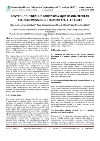
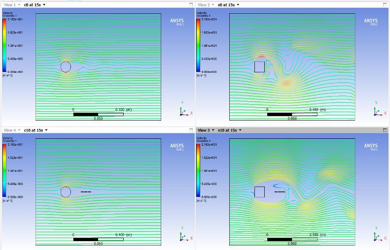
Figure 8.3Velocitycontourinallcases.
Result and Analysis
We use CFD Post for result and post processing. Here we comparetheresultofflowofwaterinaReynold’snumber of2*105
9.1Graphical results and result comparison
9.1.1 Graph of pressure on the body
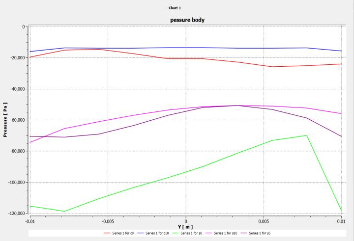
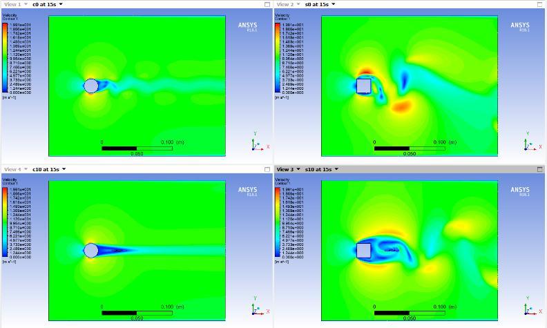
Figure 8.1Pressurecontourinallcases.
Figure 8.2Streamlinesinallcases.
Figure 9.1.1Graphofpressureonthebody.
The graph shown above shows the variation of pressure with distance from the body to right. The point taken as zeroistherightmostpointinthebody.Thecolourcodeis definedbelow.
Theredlineindicatesthepressureexertedon thecircularcylinderwithnosplitterplate.
Thebluelineindicatesthepressureexerted onthecircularcylinderwithsplitterplateinaD/H ratioof1.0.
International Research Journal of Engineering and Technology (IRJET) e ISSN: 2395 0056
Volume: 09 Issue: 06 | June 2022 www.irjet.net p ISSN: 2395 0072
Thegreenlineindicatesthepressureexerted onthesquarecylinderwithnosplitterplate.
______
Thepinklineindicatesthepressureexerted onthecircularcylinderwithsplitterplateinaD/H ratioof1.0.
9.1.2 Pressure comparison
Sl no. Geometr y Config uratio n D/H
Pressure at reference point Y=0 (Pa)
Pressure at maximum of variation Y=8mm (Pa)
Variation (Pa)
Thepinklineindicatesthepressureexerted onthecircularcylinderwithsplitterplateinaD/H ratioof1.0.
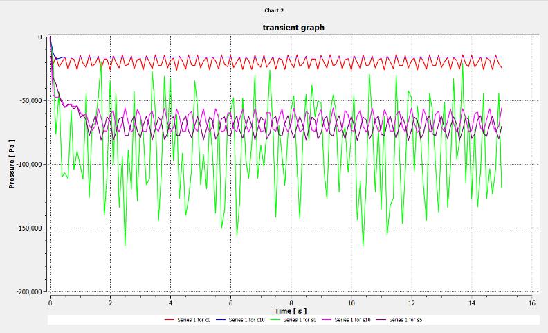
9.1.4 Transient pressure comparison
Sl. no Geometry Config uration (D/H)
Maximu m amplitud eafter8s (Pa)
Minimum amplitude after8s (Pa)
Variati on (Pa)
1 Square cylinder 0 50,000 1,40,000 90,000
2 1 40,000 30,000 10,000
1 Square cylinder
0 55,000 70,000 15000
2 1 95,000 50,000 45000
3 Circular cylinder 0 20,000 15,000 5000
4 1 15,000 15,000 0
Table 9.1.2Pressurecomparison.
9.1.3 Graph on transient pressure
Figure 9.1.2Graphontransientpressure.
The graph shown above shows the variation of pressure with distance from the body to right. The point taken as zeroistherightmostpointinthebody.Thecolourcodeis definedbelow.
Theredlineindicatesthepressureexertedon thecircularcylinderwithnosplitterplate.
3 Circular cylinder 0 15,000 25,000 10,000
4 1 15,000 15,000 0
Table 9.1.4Transientpressurecomparison.
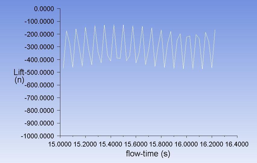
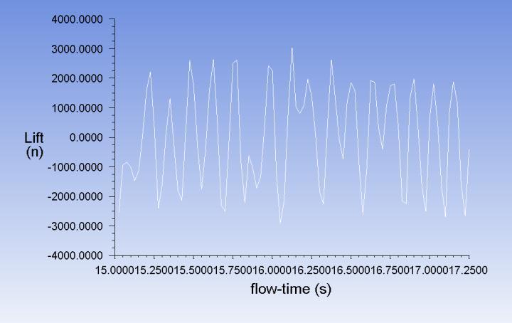
9.1.5 Variation of lift force in circular cylinder with no splitter plate.
Figure 9.1.5Variationofliftforceincircularcylinder withnosplitterplate.
Thegraphshownaboveshowsthevariationofliftforcein circularcylinderwithnosplitterplate.Thereisanaverage amplitude of -225N and -475N. So a mean variation of 250Nisobtained.
______
Thebluelineindicatesthepressureexerted onthecircularcylinderwithsplitterplateinaD/H ratioof1.0.
Thegreenlineindicatesthepressureexerted onthesquarecylinderwithnosplitterplate.
Volume: 09 Issue: 06 | June 2022 www.irjet.net p ISSN: 2395 0072
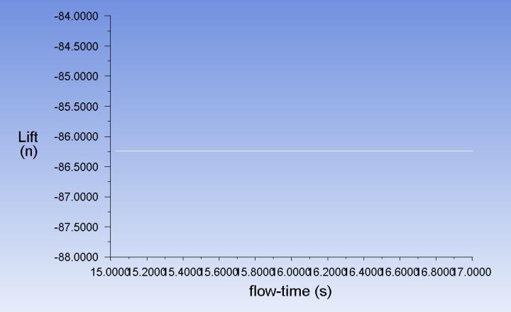
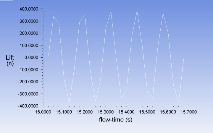
9.1.6 Variation of lift force in circular cylinder with splitter plate in a D/H ratio of 1.0.
9.1.8 Variation of lift force in square cylinder with splitter plate in a D/H ratio of 1.0.
Figure 9.1.6Variationofliftforceincircularcylinderwith splitterplateinaD/Hratioof1.0.
Thegraphshownaboveshowsthevariationofliftforcein circular cylinder with splitter plate in a D/H ratio of 1.0. There is an average amplitude of 86.75N and 86.75N. So thereisnovariationatall.
9.1.7 Variation of lift force in square cylinder with no splitter plate.
Figure 9.1.8Variationofliftforceinsquarecylinder withsplitterplateinaD/Hratioof1.0.
Thegraphshownaboveshowsthevariationofliftforcein square cylinder with splitter plate in a D/H ratio of 1.0. There is an average amplitude of 350N and 375N. So a meanvariationof250Nisobtained.
9.1.9 Lift force comparison
Sln o Geometr y Configu ration (D/H)
Maximum amplitude afterfirst cycle (N)
Minimum amplitude afterfirst cycle (N)
Variati on (N)
1 Square cylinder 0 225 250 475 2 1 350 375 725 3 Circular cylinder 0 225 475 250 4 1 8675 8675 0
Table 9.1.9Liftforcecomparison.
Figure 9.1.7Variationofliftforceinsquarecylinderwith nosplitterplate.
Thegraphshownaboveshowsthevariationofliftforcein square cylinder with no splitter plate. There is an average amplitudeof225Nand 250N.Soameanvariationof475N isobtained.
Conclusion
In the isolated case, it is observed that the von Karman vortexstreetgeneratesalternatelyandregularly.Whenthe gapissmall,theshedvortexcollideswiththesplitterplate and is prevented from growing. This causes a reduction in the peak values of the lift and drag coefficients. It seems thatthereductioninthepeakvalueoftheliftcoefficientis caused by the rearrangement of, the vortices due to the splitterplate.Whenthegapbecomeswider, vorticesoccur betweenthebodiesandthewakeisreattached.
International Research Journal of Engineering and Technology (IRJET) e ISSN: 2395 0056
Volume: 09 Issue: 06 | June 2022 www.irjet.net p ISSN: 2395 0072
The variation of different flow properties pressure, velocity and streamline are analysed. The vortex suppression for different configurations are considered. The maximum vortex suppression was obtained from
placingamulti elementsplitterplateatadistanceassame as the diameter of the circular cylinder. Even though splitter plates are used, vortex suppression was low for squarecylinder.
When a circular cylinder is placed in a flow of Reynold’s number of 2*105 with an accompany by a splitter plate placed in a distance which is equal to the diameter of the cylinder,theflowismaintainedinastablecondition.
Propertieslikelift,pressure,velocityandstreamlinehasno changesexperienced.Itisalmostequaltoalaminarflow.
But in case of a square cylinder, even splitter plates are present,changeshavebeenoccurred.itwasnotanegligible one.
Reference
1. RezvanAbdiet.al,Reductionoffluidforcesandvortex shedding frequency of a circular cylinder using rigid splitter plates, European Journal of Computational Mechanics,volume26,page225 244,2017
2. Norio Arai and Masatomo Komatsu, Active control of the hydraulic forces of a body by a splitter plate, ComputersFluidsVol.21,No.2,pp.145 150,1992.
3. J. Xu et.al, Bifurcation Analysis Of Flow Over A Rotatable Cylinder With A Splitter Plate, AIAA 1738, 1991.
4. HuseyinAkilliet.al,Suppressionofvortexsheddingof circular cylinder in shallow water by a splitter plate, FlowMeasurementandInstrumentation16,211 219, 2005.
5. Raghuraman N Go'Vardhan and 0 N Ramesh, A Stroll downKarmanStreet, Resonance,Vo1.,S.No.12,2000.
6. A.Roshko,NACATN3169(1954).
7. J.H.Gerrard,J.FluidMech.25,401(1966).
8. S. Hoerner, Fluid Dynamic Drag. Hoerner Fluid Dynamics,pp.3 12(1965)