DESIGN OF POWER GENERATING SPEED BREAKER
I. INTRODUCTION
Energyisanimportantpartofeveryone’slife.Everyevent in day to day we require energy. But nowadays we see thereissomehowshortage ofenergyfacebyworld.Crisis
ofenergyisthemainproblemgeneratedthesedays.Many conventionalsourcesarealsodepletinglikecoal,oil,fossil fuelsetc.Wehavetofindasolutiontotheseproblemsand need to find alternative sources to generate energy as good as good. There is also increasing in population rate over the world, especiallyinIndiathe growth rateis very high. Due to rate of population increased, vehicles on roadsarealsoincreasingin largenumbers.Energycan be createdinlargeamountwhenvehiclearepassesonroads but this energy is wasted as there is no implement to use thatenergy.So,thisisourresponsibilitytousethiskindof energy for good source of purpose. By implementing specially designed speed breaker setup on roads we use energy produced from it. We can convert this mechanical engineering into useful energy. When the vehicle passes on speed breakers which are implemented in various positions to slow down the vehicles, safety purpose, the energyisproducedbythissetup.
By generating that kind of energy and overcome the energy crises problem, we made a project on this. There are many kinds of mechanism we can use in this set up like Roller mechanism, Rack and pinion mechanism, Hydraulic mechanism, Crank shaft mechanism. We use Rack and pinion mechanism in our project. The vehicle's weight and speed can be used to generate energy. The methodemploysaspeedbreakerpress,whichisthenused in conjunction with a rack and pinion arrangement to press down and run the generator motor, creating electricity. The speed breaker is returned to its original positionusingthespring mechanism. Thisiswecanstore somewhereandmaketheuseofthisenergyindaytoday life like in street lights, singles, Toll tax collection center, etc. This project is eco friendly and their less need of manpower. It is a cheap source, pollution free and requiredlessfloorarea.Andthisisarenewablesourceso depletion not occurs in this. So, we are generating electricity (energy) without depending on any other factors.Technologyalsohelpsto conserve natural source. Andlastlyitisagoodalternativesourceoverthedepleting conventionalsources.
II. LITERATURE SURVEY
Speedbumpsarekinematicsystemsthatreceivetheir kinematics from passing cars and convert generated
Volume: 09 Issue: 06 | Jun 2022 www.irjet.net p ISSN: 2395 0072 © 2022, IRJET | Impact Factor value: 7.529 | ISO 9001:2008 Certified Journal | Page2864
Prof. Shital Patel1 , Dr. S. D. Jadhav2 , Shubham Chauhan3, Omkar Chavan4 , Prajwal Bamhane5 & Niraj Bothe 6
1 Assistant Professor, 2 Professor, 3,4,,65 Student, Department of Mechanical Engineering, Bharati Vidyapeeth College of Engineering, Navi Mumbai, Maharashtra, India. ***
International Research Journal of Engineering and Technology (IRJET) e ISSN: 2395 0056

Volume: 09 Issue: 06 | Jun 2022 www.irjet.net p ISSN: 2395 0072
kinetic and potential energies to electrical energy. The mass of the driving vehicle experiences vertical translation as a result of the speed bumps systems, resultinginpotentialandkineticenergy.
For the construction of an energy conversion system for the extraction of kinetic energy from vehicles, an appropriate and efficient topology is required. The purpose of this work is to present a new speed breaker generator(SBG)forextractingkineticenergyfromvehicle trafficinthestreet.Thisdeviceconvertsthekineticenergy ofthevehiclesintoelectricenergy.
N. N. Ghuge (2014) explains vehicular traffic in big cities is more, causing a problem to human being. It has advantagethatitdoesnotutilizeanyexternalsource.Now is the moment to put these types of new ideas front and centre,andresearchshouldbeconductedtoimprovetheir impact.Thiscanbeimplementedatmetropolitancities.
III. METHODOLOGY
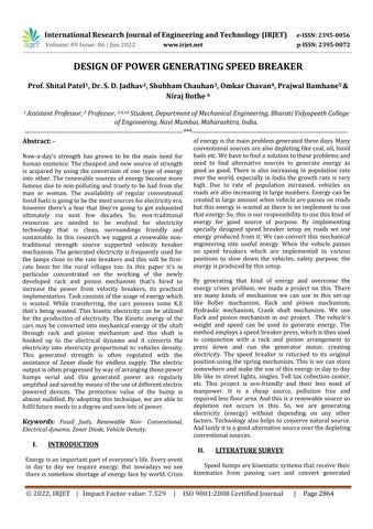
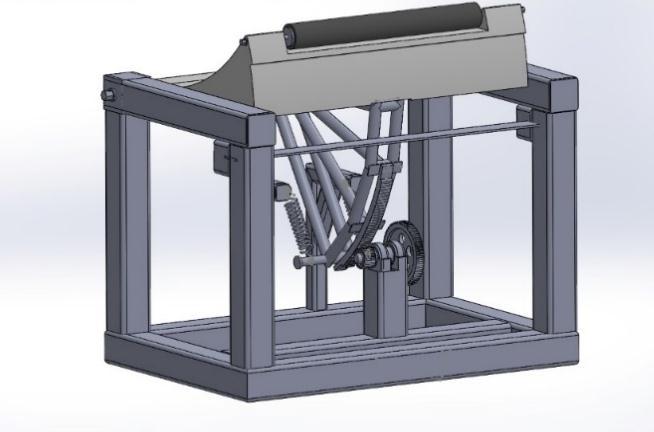
Fig.1
The principle of electricity generation through speed breaker is fundamentally based on converting the kinetic andpotentialenergiesofvehiclestoelectricenergy.When vehiclespassoverthespeedbreaker,kineticandpotential energies are produced from the vertical displacement of speed breaker. This energy is then converted into electricitywiththehelpofgeneratorandchargingcircuit.
There are number of proposed ways to convert up and down motion of speed breaker into rotary motion. They are
Rollermechanism
Crank shaftmechanism
Magneticmechanism
Rakeandpinionarrangement
HydraulicsMechanism
Inourproject,wehaveusedrakeandpinionarrangement mechanismandsomepartsofrollermechanism.
Flowchart:
SPEED BREAKER SPRING ARRANGEMENT
GENERATOR
FLYWHEEL
CYCLIC RAKE AND PINION ARRANGEMENT GEAR SYSTEM
IV. COMPONENTS USED
1) SpeedBreaker
Speed Breaker is used transform the force exerted by vehicles on the other arrangements, thereby producing downwardmotiononthecyclicrake.Thespeedbreakeris made up of C 25 carbon steel. The speed breaker is designed in such a way that the road acts as a one way. Thedimensionsofthespeedbreakerarementionedinthe followingtable.
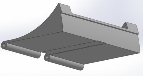
2) CurvedRack
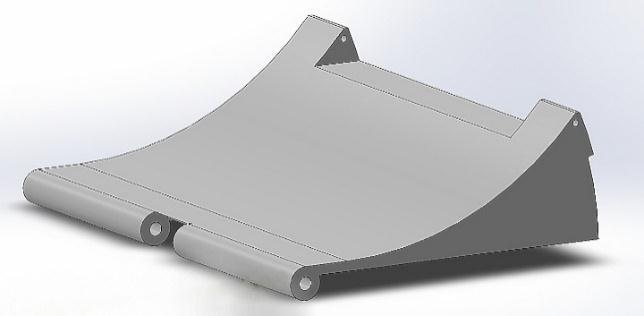
Fig.2
When an object needs to perform circular motion, then curvedrackisused.Themovingtrackofthisdevicecanbe driven by a motor situated in the middle if the diameter of the moving track is reasonably small. However, if the diameter is relatively large, the same friction force is eliminated,becausethediameterislarge,theoutputtorque of the motor is also greater. If the diameter is large, a very largeoutputtorqueislarge;theoutputtorqueofthemotor isalsogreater.
© 2022, IRJET | Impact Factor value: 7.529 | ISO 9001:2008 Certified Journal | Page2865
CHARGING CIRCUIT BATTERY
STREET LAMP
International Research Journal of Engineering and Technology (IRJET) e ISSN: 2395 0056
Volume: 09 Issue: 06 | Jun 2022 www.irjet.net p ISSN: 2395 0072
Fig.3
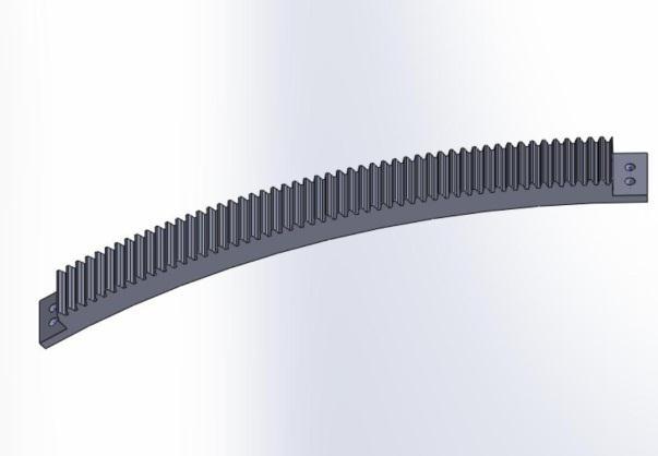
If the diameter is large, a very large output torque is required, and it is not easy to control, therefore we have used a curved rack. In this project, the speed breaker follows a rotational motion through one end of speed breaker.
3) Spring
Springsareusedinthisprojectforfollowingreasons,
Applyforce
Controlvibrationsandmotion
Reduceimpact
4) Bearing
A bearing is a machine detail that constrains relative motion and decreases friction between shifting parts to simplest the favored motion. The design of the bearing may also, for example, offer without spending a dime linear motion of the transferring part or free of charge rotation round a hard and fast axis; or, it may save you a motion via controlling the vectors of regular forces that endure at the moving elements. Many bearings also facilitate the preferred motion as a lot as viable, inclusive of via minimizing friction. Bearings used here are Ball Bearings and are installed at the crank shaft for connectingtheconnectingrod.
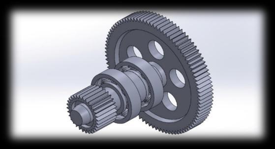
5) Gearsystem
Gears are used here for amplifying the velocity. The form ofgearsusedinthisversion isSpurGears. Twogearsout ofwhichoneisapinionandotherisabiggergearareused righthere.Thesegearsmeshwithoneanothersoonecan transmit torque. A transmission is a pair of gears that worktogethertocreateamechanicaladvantage.
6) Generator
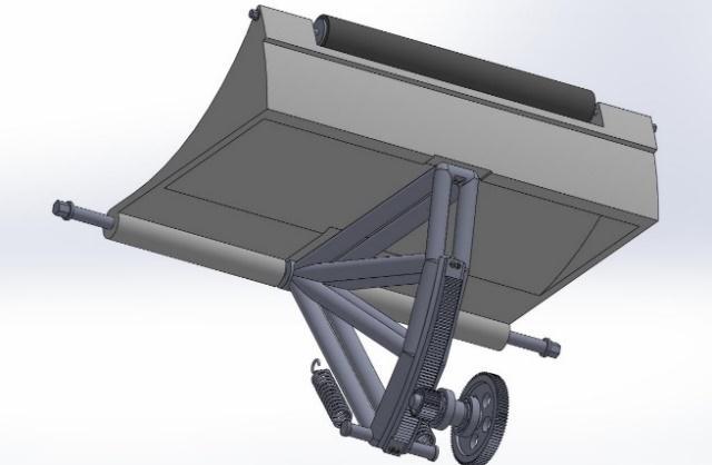
Fig.4
In this system, a 500 rpm DC generator is employed to transform mechanical input from mechanical setups into electrical output. The rotation of the shaft derived from the curved rack and pinion system feeds the input to the DCgenerator.
SpecificationsofGenerator:
CurrentCapacity=0.75A Voltage=12V Torque=2kg
V. DESIGN
Fig.5
Fig.6
©
Certified Journal | Page2866
2022, IRJET | Impact Factor value: 7.529 | ISO 9001:2008
International Research Journal of Engineering and Technology (IRJET) e ISSN: 2395 0056
VI. DESIGN CALCULATIONS
1) SpringDesign:
Specificationsofthespringsused
Type:HelicalSprings Materialofthespring=ASTMA228Steel Modulusofelasticity=G=80GPa Let,Exertedforce(P)=2000N Maximumdeflectionofspring(��)=250mm Springindex(C)=7 Syt =1760MPa Sut =2346MPa
Step1:Calculationofwirediameter, CalculatingWahlfactor(K) K=(4C 1)/4C 4)+0.615/C =1.213 τ=0.5xSut =1173MPa But,τ=8KPC/πd2 d=(8KPC/π*τ) ½ =0.00607m =6mm
Step2:Calculationofcoildiameter, D=Cd =7*6=42mm
Step3:No.ofcoils, ��=8PD3N/Gd4 N=��Gd4/8PD3 =20.375=20coils
It is assumed that the spring has square and groundends. Thenumberofinactivecoilsis2.Therefore, Nt =22Coils
Step4:Freelengthofspring,
Solidlengthofspring=Nt*d=22*6=132mm.
It is assumed that there will be a gap of 1 mm between consecutive coils when the spring is subjected to the maximumforce.Thetotalnumberofcoilsis22. The total axial gap between the coils will be (22 1)x1= 21 mm.
Freelength=Solidlength+Totalaxialgap =132+21 =153mm
Dimensionsofspringareshowninfollowingtable, Sr. No. Parameters Values
1 Material ASTMA228
2 Type Tension helical spring
3 Modulusofelasticity 210Gpa
4 Poission’sratio 0.313
5 Modulusofrigidity 80Gpa
6 Springcoildiameter 42mm
7 Springwirediameter 6mm
8 Totalnumberofcoils 22
9 Springconstant 8000N/m
10 Springdeflection 0.25m (Maximum)
11 Lengthofspring 153mm
2) GearDesign:
SpecificationsofGears: Sr. No. Parameters Pinion Larger Gear
1 Material C 30 (Carbon content 0.270 0.340%)
C 30 (Carbon content 0.270 0.340%)
2 Young’s Modulus 200GPa 200GPa
3 YieldStrength 350 550 MPa 350 550 MPa
4 Pitch Circle Diameter 55mm 165mm
5 PressureAngle 20º 20º
6 No.ofTeeth 30 95
7 Module 1.83mm 1.74mm
8 CircularPitch 5.45mm 5.45mm
9 Addendum 1.83mm 1.74mm
10 Dedendum 2.288mm 2.175mm
Volume: 09 Issue: 06 | Jun 2022 www.irjet.net p ISSN: 2395 0072 © 2022, IRJET | Impact Factor value: 7.529 | ISO 9001:2008 Certified Journal | Page2867
International Research Journal of Engineering and Technology (IRJET) e ISSN: 2395 0056
Volume: 09 Issue: 06 | Jun 2022 www.irjet.net p ISSN: 2395 0072
3) SpeedBreaker:
SpecificationsofSpeedBreaker: Sr. No Parameter Values
1 Material C 25 (Carbon content 0.220 0.290%)
Therefore,Lhr =Lmr *106/60*N, TakingN=100RPM, Lhr =76.765*106/60*100 =12794.2Hrs.
5) PowerCalculations:
DownwardTravelofspeedbreaker, S=rθ since,r=505.9mm&θ=28degree S=505.9*(28*3.142)/180 =247.66mm
1.2rotationsofsmallgearperdownstroke.
2.4 rotations of small gear in total stroke. (Down and upward)
2.4rotationsoflargegearinonetotalstroke. Foronevehicle,strokes=2 Rotationofsmallandlargegearpercarare =2.4*2=4.8
504.2mm
2 Young’sModulus 190GPa 3 ShearModulus 73GPa 4 Poission’sRatio 0.29 5 YieldStrength 240MPa 6 Length 750mm 7 Width 490.9mm 8 Height 190mm 9 Radius of Curvature of SpeedBreaker
4) BearingDesign:
LetusassumetheradialforceactingonthebearingbeFr= 3000N, From PSG 4.13, Selecting Deep groove ball bearing (DGBB) SKF6206, Andweget, d=30mm,D1 =36mm,D=62mm,D2 =56mm,B =16mm,r=1.5mm,r1 =1mm,C0 =1000Kgf,C= 1530Kgf.
We know that, Equivalent dynamic load capacity, Pe = S(VXFr +YFa) X=1, Y=0, V=1(forInnerrace), S=1.2 Hence,Pe =1.2(1*1*3000) =3600N
Therelationbetweenthebearinglifeandthedynamicload capacityisexpressedas, Lmr=(C/Pe )k Where,K=3,forballbearing, Lmr =(15300/3600) 3 =76.765millionsofrevolutions.
Rating life of bearing at 90% reliability in operating hours is, Lmr=Lhr *N*60/106,
Now,asgearratiois3 Rotations of generator shaft per stroke = rotations of any gear(smallorlarge)*3 Rotationsofgeneratorshaft=4.8*3=14.4 Now,letassume120vehiclepassesin1hour. No.ofvehiclespermin.=2 Rotationsofgeneratorshaft=28.8RPM
We should change the unit of rotational speed as rad/s (radianpersecond)
1rotation=360degree=6.28rad 1rpm=6.28/60rad/sec.=49.737 =0.10466667rad/s 28.8rpm=3.014400096rad/sec
Also,weshouldchecktheunitoftorqueisNm. Assumetheweightofvehicleis2000N Torque=2000*82.5=16500Nmm =16.5Nm
Torqueactingonbiggergear=16.5 Subtracting20%lossesweget, Torque=13.2Nm
Now,Powergeneratedisgivenby =Torque*Rotations(rad/sec) = 13.2*3.0144=39.79W(Inonemin)
VII. EXPECTED OUTCOMES
Electricity generation without depending on other factors.
3to4LEDstreetlightscanbelightened.
Technologywillhelptoconservenaturalsource
Goodalternativesourcesoverdepletingconventional source.
Pollutionfreelessfloorarea,nomanpowerrequired.
Renewablesource,sodepletionnotoccurs.
© 2022, IRJET | Impact Factor value: 7.529 | ISO 9001:2008 Certified Journal | Page2868
International Research Journal of Engineering and Technology (IRJET) e ISSN: 2395 0056
Volume: 09 Issue: 06 | Jun 2022 www.irjet.net p ISSN: 2395 0072
VIII. APPLICATIONS
This tool can be utilized in locations such as schools, publiclocations,hospitals,railwaystationsandmany others.
throughSpeedBreakerMechanism"TheInternational Journal of Engineering and Science (IJES), Volume 5, Issue4,2016
We designed and manufactured this tool such that every company huge or small may want to have enoughmoneyit.
2) Amal Abraham, CibinGeevarghese Jacob,Glen Martin Thomas,Jobby George,Jose Tom,"Eco Friendly Power Generation from SpeedBreakers" IJIRST International Journal for Innovative Research in Science&Technology,Volume3,Issue11,April2017
It is designed such that a three storey constructing wastemaybeincineratedwithoutdifficulty
AlsousedinStreetlight,lamppost,avenuelamp,light widespread, or lamp. Modern lamps may have mild sensitive photocells to show them on at dusk, off at sunrise,oractivatemechanicallyindarkishclimate.
3) Ankit Gupta, Kuldeep Chaudhary & B.N Agrawal, " An experimental study of generation of Electricity using Speed breaker", International Journal of Mechanical Engineering(IJME),Vol.1,Issue1,Aug2012.
Traffic Lights: Traffic lighting, which will also be known as stoplights, visitor lamps, traffic alerts, signal lighting fixtures, robots or semaphore, are signaling devices located where we can apply this project.
IX. CONCLUSION
Kinetic energy and downward force exerted on road by vehicles which were losing is made in use inthisproject.
4) D.Venkata Rao, K.Prasada Rao, S.Chiranjeeva Rao and R.Umamaheswara Rao, "Design and Fabrication of Power generation System using Speed Breaker" Accepted 10 June 2014, Available online, Vol.4, No.4 Aug2014.
5) Md. Emran Hossain, Md. Rokib Hasan, KaziTahsan Ahmed, Md. NaoshatMunimShawon, " Design and Performance of Power Generation Using Speed BreakerwiththeHelpofRackandPinionMechanism" Proceedingsofthe20174thInternationalConference on Advances in Electrical Engineering, Dhaka Bangladesh,28 30September,2017.
This wastage factors are used for power which is generatedbythisspeedbreakermechanism
Efficiencyisbeenincreasedduetosmoothworking ofmechanism.
6) Mrs. S.S Pitre, Mr. Rahul Raj, Mr. Sachin Raina, Mr. AkashBhoria,Mr.AlokKumar,"ElectricityGeneration Using Speed Breaker" (IRJET), Volume: 05, Issue: 03, Mar 2018.
Frictional losses in previous designs are been reduced to greater extent, therefore the power is generatedmoreefficiently.
No other equipments are required to make the roadstoworkasonewayasthismechanismisone side mechanism. Also, modification can be done to makeittoworkastwo waymechanism.
7) Miss.GaMiss,GauriS.Khakare,Miss.JyotiM.Pathade, Mr.NitinD.Khomane,Miss.PoojaW.Belikar,Prof.P.J. Bhakre, "Design of Hardware Model for Electricity GenerationbySpeedBreakerthroughRackandPinion Mechanism" International Research Journal of Engineering and Technology (IRJET), Volume: 05, Issue:06,June2018.
In different phrases installing an energy generator mechanism on road will provide energy that may be applied to lighten city streets, boulevards, and supply low voltage powers to cameras or velocity sensors.
X. REFERENCES
Research Papers:
1) Jyoti Maurya,Pooja Gupta, Pooja Gupta,Tarannum Shahab,AmitabhSrivastava,"GenerationofElectricity
8) Pruthviraj Jadhav,Abhishek Raykar, Saurabh Kuntala, AmolPatil, "Design, Fabrication and Testing of power generation Using vehicle movement by flywheel mechanism",JETIR,Volume6,Issue4,April2019.
9) Shah MohazzeShah, MohazzemHossaina, C. K. Dasb, Md. ShahdatHossanc, SamsJarind, "Electricity from Wasted Energy of the Moving Vehicle Using Speed Breaker",ArticleinJournalTeknologi,March2015.
10) M.Sailaja,M.RajaRoy,S.PhaniKumar,"DesignofRack andPinionMechanismforPowerGenerationatSpeed Breakers"(IJETT) Volume22,Number8 April2015.
© 2022, IRJET | Impact Factor value: 7.529 | ISO 9001:2008 Certified Journal | Page2869
International Research Journal of Engineering and Technology (IRJET) e ISSN: 2395 0056
Volume: 09 Issue: 06 | Jun 2022 www.irjet.net p ISSN: 2395 0072
Books Referred:
1) DesignofMachineElementsbyV.B.Bhandari.
2) PSGDataBook.
© 2022, IRJET | Impact Factor value: 7.529 | ISO 9001:2008 Certified Journal | Page2870