International Research Journal of Engineering and Technology (IRJET) e ISSN: 2395 0056
Volume: 09 Issue: 06 | Jun 2022 www.irjet.net p ISSN: 2395 0072
International Research Journal of Engineering and Technology (IRJET) e ISSN: 2395 0056
Volume: 09 Issue: 06 | Jun 2022 www.irjet.net p ISSN: 2395 0072
1Student, Dept of ECE, GCE Tirunelveli, TamilNadu ,India
2Professor,Dept of ECE, GCE Tirunelveli, TamilNadu, India ***
Abstract Free space optics (FSO) is a Optical communication technique that starts to evolve the world into a modernizedsociety by securing and fast transmissible of data through air medium without much contamination of the environment by transmitting a high power laser beam through free space. Wavelength Division Multiplexing (WDM)combinesthedatafromdifferentcarriersignalsinto a single signal using non ideal wavelengths with larger bandwidth. FSO communication is implemented by using 4 different Multiple Input Multiple Output (MIMO) channels i.e.,(2x2,4x4,8x8 &16x16) and a amplifier series using adaptive optimization, a technique that grands an advantage over an varying environment such as rain, mist, fog, etc., that causes the attenuation of the signal and analyse the result by various factor such as BER and Quality factor vs Distance, data rate and attenuation using Optisystem16.0.
Key Words: Free Space Optics (FSO), Wavelength Division Multiplexing (WDM), MIMO Channel, Bit Error Rate(BER), Quality Factor.
OpticalCommunicationhasbeenamajorcontributor in the development of modern 21st century. With improvement in the modern technology the usage of spectrum bandwidth creates a major issue. Data Privacy and Encoding are beginning to be major problem in cybernetic world developments. FSO technology brings a solution to this problem by transmitting the data through theairmediumwithhelpoftheLaseroranyotheroptical signalfortransmission
Currently, Free Space Optics is capable of several Gigabitsofdata,voiceandvideocommunicationsthrough theair,whichallowsopticalconnectivitywithoutrequiring fiber optic cable or securing spectrum licenses. Communication links typically operate between the 780 1600nmwavelengthsbandsanduseOpticaltoElectricand Electric to Optic converters. FSO requires light, which can be focused by using either light emitting diodes (LEDs) or
lasers (light amplification by stimulated emission of radiation.
FSO communication is consider as an alternative to radiorelaylinkline ofsight(LOS)communicationsystems. FSO communications can provide high data rates in Gbps range through the atmosphere for range from a few hundreds of meters to a few kilometers. FSO channel is considered to be air medium where atmospheric attenuationfactorsplaysamajorrole.
Loss in the FSO system happens due to attenuation caused by different weather conditions and the Line of sight of the signal transceived. Attenuation is a telecommunications term that refers to a reduction in signal strength commonly occurring while transmitting analog or digital signals over long distances, Signal attenuation within the optical fibers is usually expressed inthelogarithmicunitofthedecibel.Decibelisdefinedby theinputandoutputpowerratioofthesignalforaspecific operating wavelength. The overall signal attenuation is defined by the number of dB, which is expressed as given below
dB=10log10 (Pin/Pout)
The atmospheric attenuation in FSO communication system is mainly caused by the Mie scattering and local weather condition. The atmospheric attenuation is time varying and will depend on the current local conditions andweather.
In general, the atmospheric attenuation is given by thefollowingBeer’slaw, τ=eβL
where β is the total atmospheric co efficient, contributed by absorption and scattering and L is the distancebetweenthetransmitterandreceiver.
2022, IRJET | Impact Factor value: 7.529 | ISO 9001:2008 Certified Journal

International Research Journal of Engineering and Technology (IRJET) e ISSN: 2395 0056
Volume: 09 Issue: 06 | Jun 2022 www.irjet.net p ISSN: 2395 0072
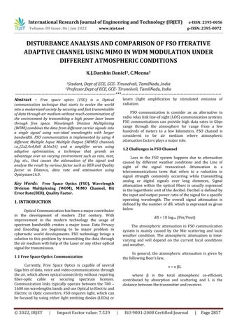
The four models of FSO links are four different number of channels (2x2,4x4,8x8,16x16) operating at a wavelength of 1550nm by using different modulation formats i.e. NRZ and RZ. The FSO system consists of transmitter, propagation medium and receiver which is shown in fig. 3. The free space channel between the transceiver is the propagation medium that is use to transmit the light signal. Optical wireless communications useslightatnearinfraredfrequencytocommunication.
different laws and practical stimulation that produce the followingtable:
S.No Atmospheric Condition Attenuation(dB/km)
1. Rain 15 2. Haze 4.5 3. Snow 20 4. Fog 25 5. ClearWeather 1 6. Turbulence 1.5 7. Dust 7
TheFSOsystemisnotmuchdifferentfromfiberoptic communication where the difference relies in the propagation medium. In the Optisystem 16 software, the FSO channel is model between an optical transmitter and optical receiver where the attenuation takes place. The adaptivechannel optimizationisachievedwiththehelpof a switch circuit that chooses the path which has inline amplifier that activates the amplifier circuit based on the visibility of the channel, thus optimizing the channels performance byadaptive optimization. Attenuation occurs due to presence of different atmospheric disturbances in the channel that is analyzed by considering standard attenuationvaluesfordifferentatmosphericcondition.
Table -1: StandardAttenuationValues
For Different Atmospheric Codition(in dB/km)
Rain 15 Dust 7 Haze 7 scintillation 1.5
Fog 25 Snow 20
ClearWeather 2
FSO communication (FSO) channel which used for propagation of signal in the channel, which attenuates the signal in presence of the environment. FSO channel has a attenuation value that varies based on different atmospheric conditions they are standardized using
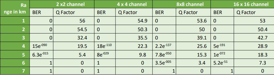
A FSO Adaptive channel is designed with help of Optisystem simulator that compares different Bit Error Rate(BER) and Q factor for different atmospheric conditionsacrossdifferentMIMOChannelsatadatarateof 2Gpsoperatingatamodulatingfrequencyof1550nm±for 16differentmessagesignals.
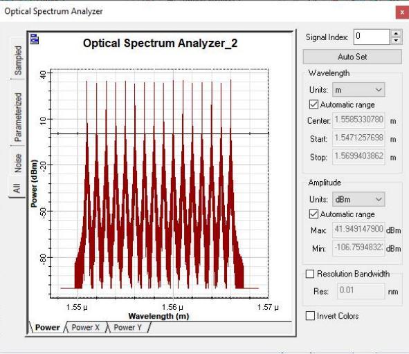
Fig –
The 2 x 2 Free Space Optical channel consisting of 2 copies of the modulated signal transmitted through 2 different FSO channels at a varying range and attenuation valuesareshowninfigure3.
International Research Journal of Engineering and Technology (IRJET) e ISSN: 2395 0056
Volume: 09 Issue: 06 | Jun 2022 www.irjet.net p ISSN: 2395 0072
The16x16FreeSpaceOpticalchannelconsistingof 16 copies of the modulated signal transmitted through 16 different FSO channels at a varying range and attenuation valuesareshowninfigure6.

Fig 3: Layoutdiagramof2x2FSOChannel
The 4 x 4 Free Space Optical channel consisting of 4 copies of the modulated signal transmitted through 4 different FSO channels at a varying range and attenuation valuesareshowninfigure4.
Fig 6: LayoutDiagramof16x16Channel
Fig 4 : Layoutdiagramof4x4FSOChannel

The 8x8 Free Space Optical channel consisting of 8 copies of the modulated signal transmitted through 8 different FSO channels at a varying range and attenuation valuesareshowninfigure5.

Fig 5: Layoutdiagramof8x8FSOChannel
3.2.
In digital transmission, the number of bit errors is the number of received bits of a data stream over a communication channel that have been altered due to noise, interference, distortion or bit synchronization errors.
The Bit Error Rate (BER) is the number of bit error perunittime.Thebiterrorratioisthenumberofbiterrors divided by the total number of transferred bits during a studied time interval. Bit error ratio is a unit less performance measure, often expressed as a percentage This visualize allows the user to calculate and display the biterrorrateofanelectricalsignalautomatically.
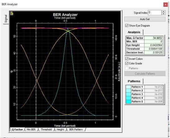
It can estimate the BER using different algorithms such as Gaussian and Chi Squared and derive different metrics from the eye diagram, such as Q factor, eye opening,eyeclosure,extinctionratio,eyeheight,jitter,etc. It can also take in account Forward Error Correction, plot BERpatternsandestimatesystempenaltiesandmargins.
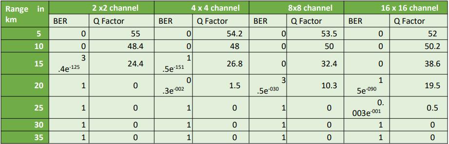
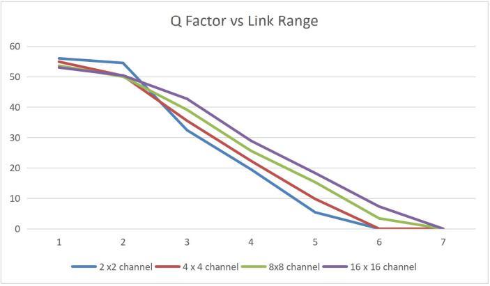
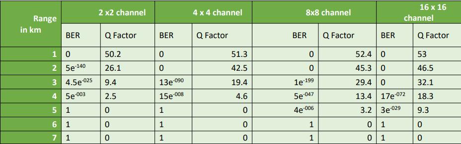
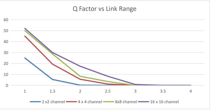
In clear weather conditions with a attenuation standardized to a value of about 1db/km the various Q factor and BER factors across 4 different FSO channel models for a link range of about 1 35 km are given as follows
International Research Journal of Engineering and Technology (IRJET) e ISSN: 2395 0056
Volume: 09 Issue: 06 | Jun 2022 www.irjet.net p ISSN: 2395 0072
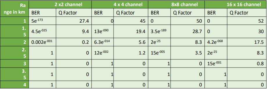
InTurbulenceweatherconditionswithaattenuation standardized to a value of about 1.5db/km the various Q factor and BER factors across 4 different FSO channel models for a link range of about 1 35 km are given as follows.
Fig –
It shows that, the use of adaptive optimized channel increases the Q factor value of about 60.6 in 2x2 channel andwiththeincreaseinlinkrange,16x16channelsshows best transmission rate in comparison to other MIMO channels.
10
It shows that, the use of adaptive optimized channel increases the Qfactorvalueof about 59.12 in2x2channel andwiththeincreaseinlinkrange,16x16channelsshows best transmission rate in comparison to other MIMO channels.
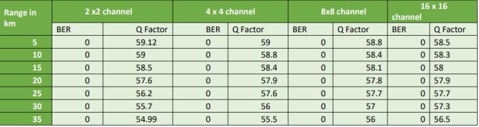
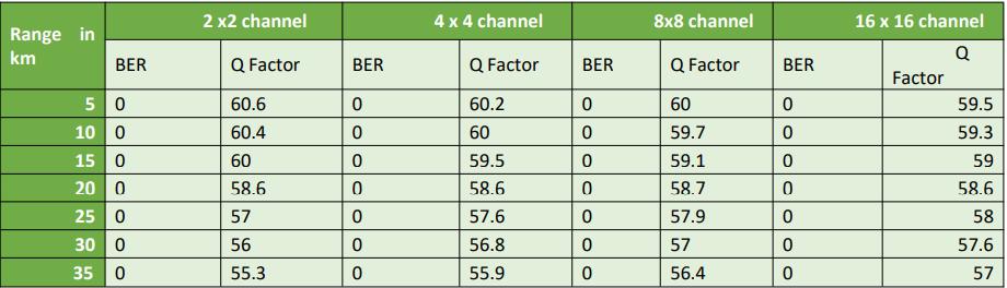
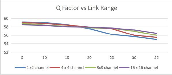
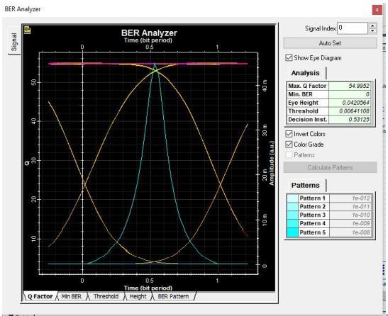
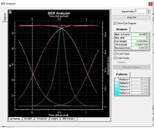
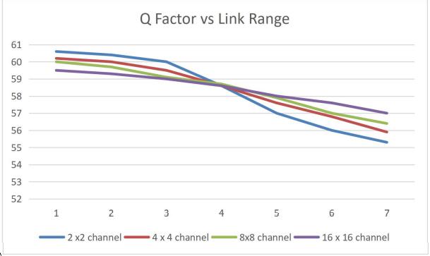
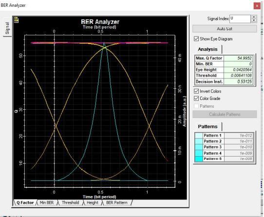
Fig – 8: EyeDiagramof2x2channelatclearweather (35km)
It shows that at clear weather conditions the link range ofthesignal canlastabove 35kmsasa resultof the adaptiveoptimizedchannelandtheBER &Qfactorvalues gets increased with increase in MIMO channels for longer distances.
Fig11:EyeDiagramof2x2channelatTurbulence35km
Fig 12:
It shows that at turbulence weather conditions the linkrangeofthesignalcanlastabove35kmsasaresultof the adaptive optimized channel and the BER & Q factor
2022, IRJET | Impact Factor value: 7.529 | ISO 9001:2008 Certified Journal
International Research Journal of Engineering and Technology (IRJET) e ISSN: 2395 0056
Volume: 09 Issue: 06 | Jun 2022 www.irjet.net p ISSN: 2395 0072
values gets increased with increase in MIMO channels for longerdistances.
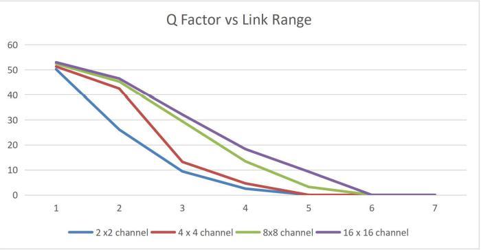
In Haze weather conditions with a attenuation standardized to a value of about 4.5db/km the various Q factor and BER factors across 4 different FSO channel models for a link range of about 1 35 km are given as follows
It shows that at haze weather conditions the link range ofthesignal canlastabove 15kmsasa resultof the adaptiveoptimizedchannelandtheBER &Qfactorvalues gets increased with increase in MIMO channels for longer distances.
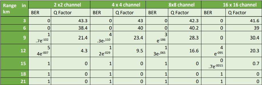
In Dust weather conditions with a attenuation standardized to a value of about 7 db/km the various Q factor and BER factors across 4 different FSO channel modelsforalinkrangeofabout1 21kmare
It shows that, the use of adaptive optimized channel increasestheQfactorvalueofabout55in2x2channeland withtheincreaseinlinkrange,16x16channelsshowsbest transmissionrateincomparisontootherMIMOchannels.
It showsthat,theuseofadaptiveoptimizedchannel increases the Q factor value of about 43.3 in 2x2 channel andwiththeincreaseinlinkrange,16x16channelsshows best transmission rate in comparison to other MIMO channels.
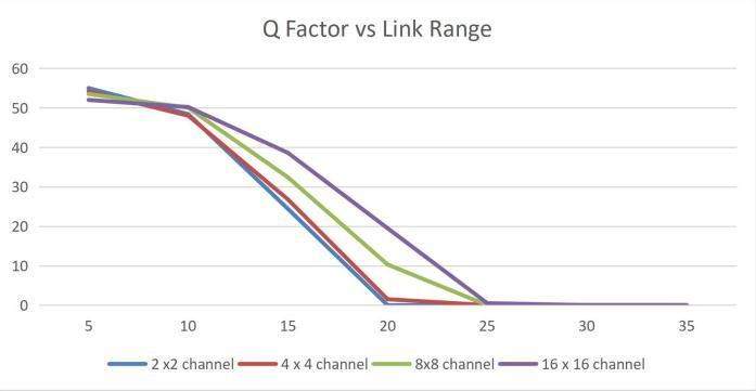
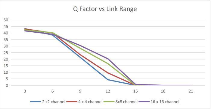
Fig 14: EyeDiagramof2x2channelatHaze(5km)
Fig 15: BER&Q FactoracrossMIMOchannels
Fig 17:EyeDiagramof2x2channelatDust
International Research Journal of Engineering and Technology (IRJET) e ISSN: 2395 0056
Volume: 09 Issue: 06 | Jun 2022 www.irjet.net p ISSN: 2395 0072
It shows that at dust weather conditions the link range ofthesignal canlastabove 12kmsasa resultof the adaptiveoptimizedchannelandtheBER &Qfactorvalues gets increased with increase in MIMO channels for longer distances.
In Rain weather conditions with a attenuation standardized to a value of about 15db/km the various Q factor and BER factors across 4 different FSO channel modelsforalinkrangeofabout1 7kmaregivenasfollows

Itshowsthatatrainweatherconditionsthelinkrange ofthesignalcanlastabove6kmsasaresultoftheadaptive optimized channel and the BER & Q factor values gets increased with increase in MIMO channels for longer distances.
In Haze weather conditions with a attenuation standardized to a value of about 20db/km the various Q factor and BER factors across 4 different FSO channel models for a link range of about 1 7 kms are given as follows.
It shows that, the use of adaptive optimized channel increasestheQfactorvalueofabout56in2x2channeland withtheincreaseinlinkrange,16x16channelsshowsbest transmissionrateincomparisontootherMIMOchannels.
It shows that, the use of adaptive optimized channel increasestheQfactorvalueofabout30in2x2channeland withtheincreaseinlinkrange,16x16channelsshowsbest transmissionrateincomparisontootherMIMOchannels.
International Research Journal of Engineering and Technology (IRJET) e ISSN: 2395 0056
Volume: 09 Issue: 06 | Jun 2022 www.irjet.net p ISSN: 2395 0072
It shows that at snow weather conditions the link range of the signal can last above 4kms as a result of the adaptiveoptimizedchannelandtheBER &Qfactorvalues gets increased with increase in MIMO channels for longer distances.
In Haze weather conditions with a attenuation standardized to a value of about 25db/km the various Q factor and BER factors across 4 different FSO channel modelsforalinkrangeofabout1 4kmaregivenasfollows
Itshowsthatatfogweatherconditionsthelinkrange ofthesignalcanlastabove2kmsasaresultoftheadaptive optimized channel and the BER & Q factor values gets increased with increase in MIMO channels for longer distances.
The model system encompasses an n channel WDM multiplexed adaptive FSO system operating at 2 Gbps using different MIMO formats for 20dbm input power at various weather conditions. Afterwards, adaptive optimization technique enables FSO signals to be improved and travelled long distances by optimizing post amplification system between the transmitter and receiver.InFreeSpace Optical system,the16x16MIMO channel performs better than other MIMO channels at all weather conditions as it performs a link range of more than 35kms in clear and turbulence and 3kms in fog weatherconditionswithaminimumBiterrorrateof0and 15 e =001 and maximum Q factor of 57 and 0.8 respectively. Furthermore, low distance performance is enhanced by increasing the number of channels and throughtheuseofadaptiveoptimizedchannel.
It shows that, the use of adaptive optimized channel increasestheQfactorvalueofabout25in2x2channeland withtheincreaseinlinkrange,16x16channelsshowsbest transmissionrateincomparisontootherMIMOchannels.
[1]. Kavitha Thandapani, Maheswaran Gopalswamy, Sravani Jagarlamudi and Naveen Babu Sriram. “Performance analysis of WDM free space optics transmissionsystemusingMIMOtechniqueundervarious atmosphericconditions”,2021.
[2]. Sree Madhuri Aovuthu, Govardhani Immadi. “Experimental studies on the effects of fog and haze on FSOlinkat405nm”,2020.
[3]. Jinka Venkata Aravind, Sanjay Kumar, and Shanthi Prince.”Performance Analysis of UWOC using SISO and SIMO Techniques.,Journal of Physics: Conference Series”,2021.
[4].A O Aldhaibani, K S Bin Sahaq , S A Binajjaj , HBakarman.”Performance Analysis of 5G Millimeter Waves over Free Space Optics System”,Journal of Physics: ConferenceSeries,2021.