International Research Journal of Engineering and Technology (IRJET) e ISSN: 2395 0056

Volume: 09 Issue: 06 | Jun 2022 www.irjet.net p ISSN: 2395 0072
International Research Journal of Engineering and Technology (IRJET) e ISSN: 2395 0056
Volume: 09 Issue: 06 | Jun 2022 www.irjet.net p ISSN: 2395 0072
1M. Tech student, Dept. of Civil Engineering, Indira Gandhi Institute of Polytechnic & Engineering, Kerala, India.
2Asst. Professor, Dept. of Civil Engineering, Indira Gandhi Institute of Polytechnic & Engineering, Kerala, India.
3 HOD, Dept. of Civil Engineering, Indira Gandhi Institute of Polytechnic & Engineering, Kerala, India. ***
Abstract Reusing structuralelementsisaneffectivewayto prompt sustainable development with reduced energy consumption and gas emission. In current practice, steel members can be easily deconstructed and reused whilst the recycling of structural materials in steel concrete composite construction has been found challenging. With the increasing material consumption in composite construction due to their well recognized structural benefits, it is essential to explore the demountability of such structures. Limited previous research indicates that there is a lack of understanding or mature design specification for demountable composite connections. This paper thus presents an innovative design of demountable K joints with concrete filledsteeltubular(CFST) chords and circular hollow section (CHS) braces connected using blind bolts. A detailed finite element analysis (FEA) modelling was established and validatedagainstreportedtest data on bolted CFST connections. The model was then used to investigate the performance of different shapes of braces in k joint. Also, it was analysed to find out which brace angle of the k joint gives the better performance and for parametric investigation using the length (gap) between the braces.
Key Words: FEA, CFST, k joint, CHS, demountability, composite construction.
Totalworldcrudesteelproductionin2017was1689million tones, approximately 50% of which was attributed to buildings and infrastructure. To reduce the negative environmental effect,itis encouragedworldwideto reuse constructionalmaterials.Theideaofreusingstructuralsteel has been adopted in practical designs such as the Sydney Olympicstadiumandtemporarycarpark inUK.Generally, thekeydesignofsuchdemountablestructuresliesintheir deconstructiveconnections,whichareusuallyachievedby usingdemountableshearconnectorsorblindbolts.[3]
CFST (concrete filled steel tubular) K joint is joints with concrete filled steel tubular (CFST) chords and hollow section braces connected using blind bolts. CFST K joints formedbyconcretefilledchordsandhollowsection(CHS) bracesarelikelyusedinpractice.Theinfilledchordconcrete contributedtorestrainingthesurfaceplasticityfailureand
enhancedthetensileperformancefortubularconnections andtheoverallstructure.Theyarecommonlyusedinlarge scale structures, e.g., long span bridges and transmission towers, and temporary structures such as offshore platforms.[1]
Atubularjointisoneoftheefficientjointformscommonly usedinsteeltubularstructures.Ithastheadvantagesofless steelconsumption,goodmechanicalbehaviour,clearpathof force transmission and large bearing capacity. Hybrid tubularK jointswithcircularbracesandsquarechordmeet the requirements of structural form and mechanical propertiesandareeasytodesignandconstruct,whichare widely used in practical engineering. On the other hand, stainless steel structures have the advantages of good durability, easy processing, high temperature resistance, excellentmechanicalpropertiesandbeautifulappearance. They have been paid more and more attention in architecturalandstructuraldesigns.
Themainobjectivesofthisstudyare:
Toinvestigatetheperformanceofdifferentshapesof bracesintheK joint.
Toexaminewhichbraceangleofthekjointgivesthe betterperformance
To study the performance of different gap distances betweenthebracesintheK joint.
Thestudyfocusesonthefiniteelementanalysisofk joint usingdifferentposition,angles,crosssectionofbracesunder nonlinear conditions. The study is only limited to k joint usedforstructuralsteelhollowsections.
In general, validation is the process of determining the extenttowhichthemodelrepresentsthereal lifesituation. Forvalidationtheforceversesdisplacementgraphobtained
International Research Journal of Engineering and Technology (IRJET) e ISSN: 2395 0056
Volume: 09 Issue: 06 | Jun 2022 www.irjet.net p ISSN: 2395 0072
frombothexperimentandnumericalmodelfromANSYSis compared.
Thekjointconsistsofachordhavingaspanof899mmand twocircularbracesofspan325mmeach.Thegapdistance(g) ofthegappedtubularK jointwas72.6mm.
SPECIMEN:K C 150×3 B 108×3
•Breadthofchord:150.07mm
•Thicknessofchord:2.94mm
•Diameterofbrace:108.55mm
•Thicknessofbrace:2.82mm
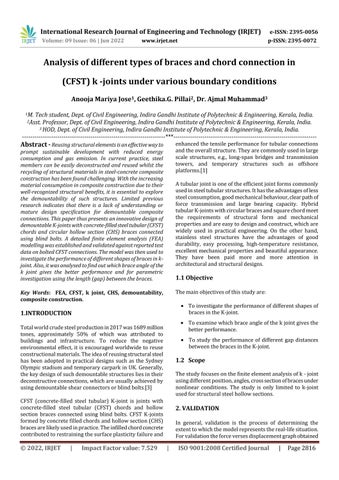
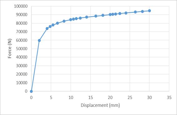
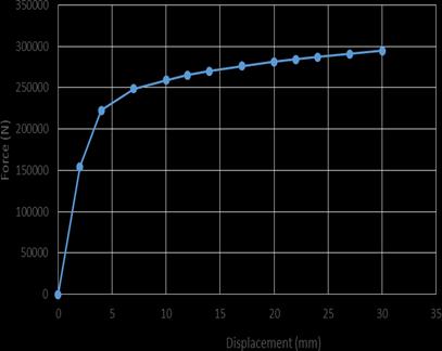
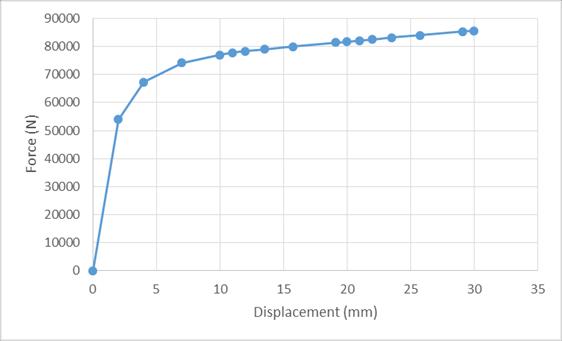
Validationisanimportantpartofthethesis.Thegeometrical dimensionsandmaterialpropertiesofkjointwasadopted fromthejournalreferred.Finiteelementmodellingofkjoint is validated bycomparingthe force displacement graphof numericalmodelwiththatofexperimentalstudyasshownin chart1and2 ComparingChat 1andChart 2itcanbeseen that force displacement graph from validation obtained is similartothatinthejournal.
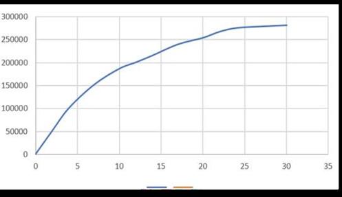
Chart 1: Forcev/sdisplacementgraphfrompaper[3]
Fig 1:Geometryofkjoint
A=Bracesubjectedtocompression
B=Bracesubjectedtotension
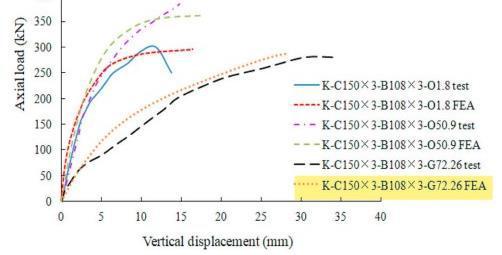
C=chordsubjectedtoaxialdisplacement
D=Fixedend
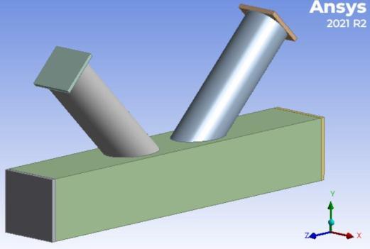
Tostimulatetherealconditions,k jointisanalysedwithone sideofsquarechordisfixedandloadisappliedastension and compression on circular end plates and axial displacementononesideofsquarechord.Themultilinear kinematic hardening rule was used for finite element analysis.
Chart 2: Forcev/sdisplacementgraphfromvalidation
The dimensions for all models were adopted from the journal and the boundary conditions was same for all models. For better understanding of the behavior of k joints the Total deformation and equivalent stress distributionwasalsoanalysedforallthemodels.
Factor value: 7.529 | ISO 9001:2008 Certified
International Research Journal of Engineering and Technology (IRJET) e ISSN: 2395 0056
Volume: 09 Issue: 06 | Jun 2022 www.irjet.net p ISSN: 2395 0072
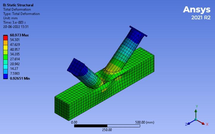
Fromthemodellingandanalysisoffourdifferentshapesof braces in the k joint, Circular braces has the maximum stressof582kNandwillundergothemaximumdeformation of60mmbeforefailure.
3.2 To examine which brace angle of the k joint gives the better performance
Intheprevioussection,wehavemodelledandanalysedthek joints with 90° brace angle for investigating the performance of different shapes of braces in the K joint. HenceinthissectionwehaveanalysedCircular,Rectangular andPentagonalbracedk jointswithbraceangle70°and 110°.
From the above figure it is observed that the maximum deformationof60.973mmhavebeenoccurredatthebottom ofbrace.Andtheminimumdeformationof0.926mmhave beenoccurredatthetopofbraces.
Table 2: ComparisonofTotaldeformationand Equivalentstressdistributionfordifferentbraceanglesin k joint
Cross sectionof braces
MaxvalueofTotal Deformationinmm
Maxvalueof Equivalentstress inMPa
70° 90° 110° 70° 90° 110°
Circle 45 60 30 725 582 612
Rectangle 30 55 30 536 575 563 Pentagon 30 30 30 563 552 558
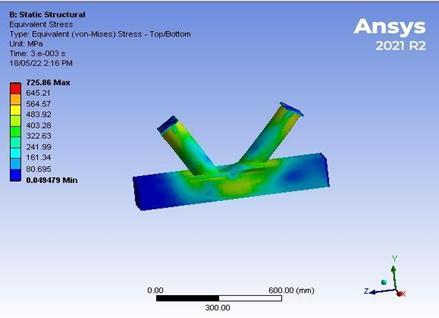
From the above table we can find that the k joint with circular braces and having brace angle of 70° have the maximumvalueofequivalentstressthanthatof110°and 90°.
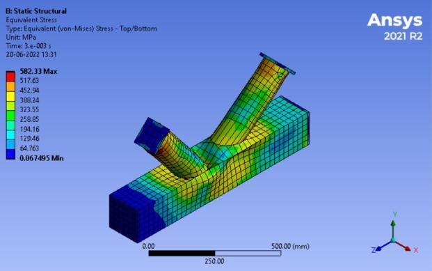
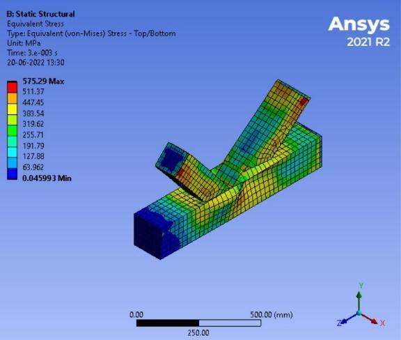
Fig 4: Equivalentstressdistributionofk jointwith Circularbraces
From the above figure it is observed that the maximum stress of 582.33MPa have been occurred at the bottom of bracesandmiddleportionofthechords.Andtheminimum stressof0.067MPahavebeenoccurredatthetopofbraces andattheendsofchords.
Table 1: ComparisonofTotaldeformationandEquivalent stressdistributionfordifferentshapesofbracesink joint
Cross sectionof braces
MaxvalueofTotal Deformationin mm
Maxvalueof Equivalentstressin Mpa
Circle 60.97 582.33
Rectangle 55.53 575.29
Hexagon 30.36 559.61 Pentagon 30.15 552.78
Fig -5: EquivalentStressDistributionofk jointwith Circularbracesandbraceangle70°
Similarly,thek jointwithrectangularbracesandhaving brace angle of 90° have the maximum value of equivalent stressthanthatof70°and110°.
International Research Journal of Engineering and Technology (IRJET) e ISSN: 2395 0056
Volume: 09 Issue: 06 | Jun 2022 www.irjet.net p ISSN: 2395 0072
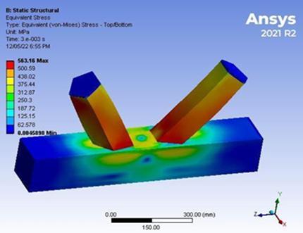
Fig 6: EquivalentStressDistributionofk jointwith rectangularbracesandbraceangle90°
Andthek jointwithpentagonalbracesandhavingbrace angleof70° havethemaximumvalueof equivalentstress thanthatof110°and90°.
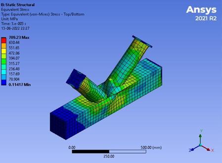
Fig 8: EquivalentStressDistributionofk jointwith circularbracesandgapdistance60mm
4.RESULT AND DISCUSSION
4.1 Performance of different shapes of braces in the K joint
The force displacement graphs of different shapes of bracesink jointwithbraceangle90°whichwasobtained fromANSYSisshownbelow.
Fig -7: EquivalentStressDistributionofk jointwith pentagonalbracesandbraceangle70°
3.3 To study the performance of different gap distances between the braces in the K-joint
Table 3: ComparisonofTotaldeformationand Equivalentstressdistributionfordifferentbracegap distancebetweenthek joint
Cross sectionof braces
Maxvalue of TotalDeformation inmm
Maxvalueof Equivalent stressinMpa
20mm 60.97 582.33 40mm 65.32 591.96 60mm 83.53 709.23
From the above table we can find that the k joint with circular braces and gap distance of 60mm have the maximumvalueofequivalentstress.
Chart 3: Performanceofcircularshapedbracesinthek joint

Chart -4: Performanceofrectangularshapedbracesinthe k joint
2022, IRJET | Impact Factor value: 7.529 | ISO 9001:2008 Certified
International Research Journal of Engineering and Technology (IRJET) e ISSN: 2395 0056
in the k joint for circular, pentagonal and rectangular shapedbraceswithsquarechordsaresummarizedbelow.
Table 5: Comparisonofmaxforcesfordifferentbrace anglesink joint
Cross section ofbraces
Chart 5: Performanceofpentagonalshapedbracesinthe k joint
Maxforcevaluefromforce displacementgraphinkN 70° 90° 110°
Circle 8.420 259 18.75 Rectangle 86.4 94.636 884 Pentagon 699 88.99 100
Theforce displacementgraphsofk jointswhichcancarry maximumforcesareillustratedbelow.
Chart 6: Performanceofhexagonalshapedbracesinthe k joint
The displacement applied and the corresponding forces obtainedfromANSYSissummarizedinthetablebelow.
Table 4: Comparisonofshapesofbracesinthek joint
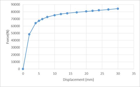
ShapeofBraces Displacement (mm) Force(KN)
Circular 30 295 Rectangular 30 94636 Pentagon 30 85.628 Hexagon 30 84335
Fromthetable4,itisclearthatthebestshapeischooseto becircular.Itholdsmaximumforcevalueof295kNwhichis comparativelymuchhigherthanothers.
`
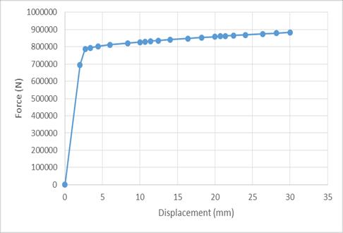
Chart 7: Performanceofcircularshapedbracesinthek jointwithbraceangle90°
Itcanbeconcludedfromtheabovedatathatk jointwith Circularshapedbraceswithbraceangle90°cancarrymax forceof259kNthanotherbraceangles.
4.2
of different brace angles in the K joint
For 30mm displacement applied the corresponding maximumforcesobtainedforbraceangles:90°,70°and110°
Chart 8: Performanceofrectangularshapedbracesinthe k jointwithbraceangle110°
Volume: 09 Issue: 06 | Jun 2022 www.irjet.net p ISSN: 2395 0072 © 2022, IRJET | Impact Factor value: 7.529 | ISO 9001:2008 Certified Journal |
International Research Journal of Engineering and Technology (IRJET) e ISSN: 2395 0056
Volume: 09 Issue: 06 | Jun 2022 www.irjet.net p ISSN: 2395 0072
Chart -9: Performanceofpentagonalshapedbracesinthe k jointwithbraceangle110°
Also, k joint with Rectangular and Pentagonal shaped braceswithbraceangle110°cancarrymaxforcesthan70° and90°.
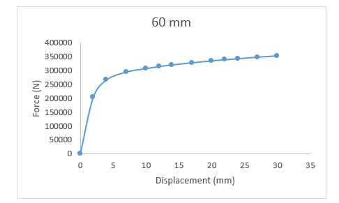
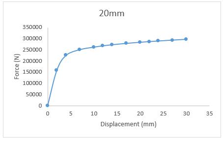
Theforce displacementgraphsobtainedfromANSYSfork joints with circular shaped braces and gap distances of 20mm,40mmand60mmisillustratedbelow.
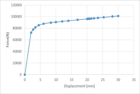
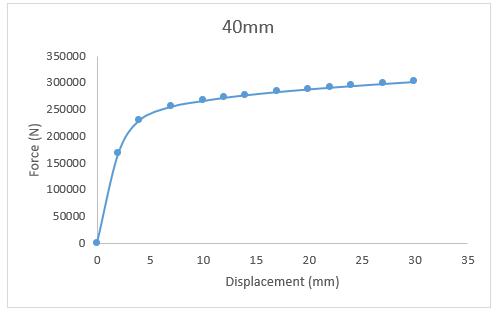
Chart 12: Performanceofcircularshapedbracesinthek jointwithgapdistance60mm
Thedisplacementappliedandthecorrespondingmaximum forcesobtainedfordifferentgapdistancesinthek jointfor circularshapedbraceswithsquarechordsaresummarized inthetablebelow.
Table 6: Comparisonofmaxforcesfordifferentgap distancesink joint
GapDistance (mm) Displacement (mm) Force(kN) 20 30 287 40 30 293 60 30 349
Fromtheabovetableitisclearthatk jointwithCircular shapedbraceswith60mmgapdistancecancarry themax forceof349kN
Chart 10: Performanceofcircularshapedbracesinthek jointwithgapdistance20mm
TheloadcarryingcapacityofK jointwithcircularbraces was higher, when compared with the other shapes of braceswhichcancarry295kNat30mmdisplacement.
K joint with hexagon braces has less load carrying capacitycomparedtoothershapesofbraceswhichcan take83.335kNat30mmdisplacement.
K jointwithcircularbracesgivesbetterperformanceat 90 ° brace angle. It can take 295 kN at 30mm displacement.
K jointwithothershapesofbraces(rectangle,pentagon, andhexagon)givesthebetterperformanceat110°brace angle. In these cases, as the angle between braces increases,theloadcarryingcapacityalsoincreases.
Chart -11: Performanceofcircularshapedbracesinthek jointwithgapdistance40mm
Theloadcarryingcapacityishigherink jointwithgap distance60mmcomparedwith20mmand40mm.
International Research Journal of Engineering and Technology (IRJET) e ISSN: 2395 0056
Volume: 09 Issue: 06 | Jun 2022 www.irjet.net p ISSN: 2395 0072
[1] Basil T Babu, Manjusha Mathew, “Numerical Study of CFSTK JointswithDifferentConnectionArrangements”, International Research Journal of Engineering and Technology (IRJET), Vol 8, Issue 7, pp. 1456 1460, 2021.
[2] Chao Hou, Lin Hai Han, Ting Min Mu, “Behaviour of CFDST chord to CHS brace composite K joints: Experiments”,JournalofConstructionalSteelResearch, Vol135,pp.97 109,2017.
[3] Dengyiding Jin, Chao Hou, Luming Shen, Lin Hai Han, “NumericalinvestigationofdemountableCFSTK joints using blind bolts” , Journal of Constructional Steel Research,Vol160,pp.428 443,2019.
[4] FangLi,Hong zhouDeng,Xiao yiHu,“Designresistance of longitudinal gusset tube K joints with 1/4 annular platesintransmissiontowers” ,Thin WalledStructures, Vol144,pp.01 13,2019.
[5] Ran Feng, Junwu Lina, “Numerical study of hybrid tubularK jointswithcircularbracesandsquarechordin stainlesssteel” ,Thin WalledStructures,Vol145,pp.01 14,2019.
[6] WenweiYang,RuhaoYan,YaqiSuo,GuoqingZhang,Bo Huang,“ExperimentalStudyonHystereticBehaviorof theOverlappedK JointswithConcreteFilledinChord” , AppliedSciences,Vol9,pp.01 17,2019.
[7] Wenyuan Kong, Yongfa Huang, Zhan Guo, Xiaoyong Zhang,YuChen,“Experimentalstudyonsquarehollow stainless steel tube trusses with three joint types and differentbracewidthsunderverticalloads”,Reviewson AdvancedMaterialsScience:60,pp.519 540,2021.
[8] JianZheng,ShozoNakamura,Kang mingChenandQing xiong Wu, ‘Numerical Parameter Analysis on Stress Concentration Factors of Concrete filled Steel Tubular (CFST) K joint under Axial Loading’, The 2017 World Congress on Advances in Structural engineering and Mechanics(ASEM17),September2017.
[9] S.Saleh,C.Hou,L.H.Han,Y.X.Hua,“Numericalbehaviour ofcompositeK jointssubjectedtocombinedloadingand corrosiveenvironment”,12thInternationalConference on Advances in Steel Concrete Composite Structures (ASCCS2018),Spain,pp.557 564,June2018
[10] Ying Chen, Qingtao Yang, Dongchen Wang, “Finite ElementAnalysisandOptimizationofthePlanar Steel Tubular K Joints”, 2021 International Conference on IntelligentPowerandSystems,China,pp.01 08,2021
2022, IRJET | Impact Factor value: 7.529 | ISO 9001:2008 Certified Journal