International Research Journal of Engineering and Technology (IRJET) e ISSN: 2395 0056

Volume: 09 Issue: 06 | Jun 2022 www.irjet.net p ISSN: 2395 0072
International Research Journal of Engineering and Technology (IRJET) e ISSN: 2395 0056
Volume: 09 Issue: 06 | Jun 2022 www.irjet.net p ISSN: 2395 0072
1Assistant Professor, Dept. of Civil Engineering, School of Engineering and Technology, Sandip University, Nashik, Maharashtra, India.
2M. Tech., Student, Dept. of Civil Engineering, School of Engineering and Technology, Sandip University, Nashik, Maharashtra, India. ***
Abstract Nowadays shear wall as structural element in high rise buildings has become a common practice. It has become the most common way to form the Lateral load resisting system in High rise structures. Veryhighstrengthand stiffness of the shear walls can be used to resist large horizontal loads and supporting Gravity loads. This makes them advantageous in many structuralapplications. Themain focus of this project is to determine the most suitable location or position for the shear wall. A G+10 RCC building subjected to earthquake loading located in zone IV is considered in this project. The equivalent Lateral force method or static method is used to calculate the Earthquake load using IS1893 (Part I):2002. Analyses were performed on ETABS. This research focuses on determining strength of shear walls in different locations. We have tried to place shear walls at different locations and an attempt has been made to check the best position for shear walls in a building. Six different cases of shear wall position for a G+10 building have been analyzed. This project aims to analyze the response of structure using by static method.
Key Words: Shearwall,ETABSEarthquake in general has long devastating history in the past. Earthquakes are most distressing and a threat to humancivilization,devastating man made structures, and human lives. It is such an unpredictable calamity that survivalmustensurethestrengthofthestructuresagainst seismic forces(13). Therefore, a lot of research works are going on around the globe for the development of better techniques that can be incorporated into structures for betterresistanceagainstearthquakes(13).Ashearwallisa structural component located in a building right from foundation level to top parapet level at various locations. Shear walls are used to defend against lateral forces. Structuralmemberswhichareusedtoresistlateralforces duetoearthquakesandwindaretheShearwalls.
Therearemanydifferentmethodsofseismicanalysislikethe time history method, response spectrum method seismic coefficientmethod,etc.(13) Astudyhasbeencarriedoutto determinethebestpossibleorientationoftheRCshearwall of a multistoried building by trying out different possible
orientations. And parameters like storey drift, base shear, nodaldisplacementareobservedandcompared
Thesixdifferenttypesofmodelsareasfollows(Fig:4 9)
1. WithoutaShearwall
2. ShearwallattheCentre ForLiftcoresonly
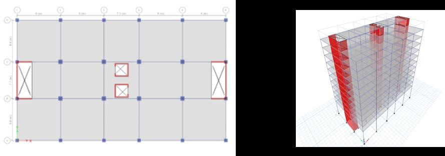
3. ShearwallsatPeriphery
4. ShearwallsatCorners
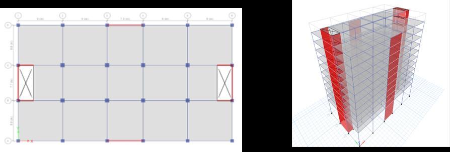
5. Shear wall along both Longitudinal faces & Lift cores
6. ShearwallalongwithbothLateralfaces&Liftcores
In this project, different position of shear wall is given.Shearwallgivesmorestabilitytothebuilding’sthan normalwall.ThisbuildingislocatedinDelhi,zoneIV.This projectgiveideaaboutshearwalllocation.Thisisalsoshow thatthebehaviorofshearwallinthebuildingsatdifferent location. This project gives idea about displacement, drift, shear.
The location of the shear walls depends on the plan of structure,corelocation,thesymmetryofthebuilding,andthe lateralforceexperiencedbythestructure.Mostly,shearwalls shouldbeplacedaroundtheouterwallsofthebuildingina symmetricalform. Itisusuallyverydifficulttofindasuitable locationfortheshearwallinthestructure.However,theideal place is the center of the building. Sometimes, structural analysis is performed to identify the ideal location in the structure.
Shear wall is a structural member positioned at different places in a building from foundation level to top parapet level,usedtoresistlateralforcesi.eparalleltotheplaneof thewall.Therearedifferentmaterialsbywhichshearwall canbeconstructed,butreinforcedconcrete(RC)buildings often have vertical plate like Reinforced concrete walls (Figure 1) in addition to slabs, beams and columns. Their thicknesscanbeaslowas150mm,orashighas400mmin
International Research Journal of Engineering and Technology (IRJET) e ISSN: 2395 0056
Volume: 09 Issue: 06 | Jun 2022 www.irjet.net p ISSN: 2395 0072
highrisebuildings.Shearwallsareusuallyprovidedalong bothlengthandwidthofbuildings.
1.2 Flow chart
Fig -1:FlowChart
Shearwallsmustprovidethenecessarylateralstrengthto resist horizontal earthquake forces. When shear walls are strongenough,theywilltransferthesehorizontalforcesto the next element in the load path below them (13). These othercomponentsintheloadpathmaybeothershearwalls, floors,foundationwalls,slabsorfootings.
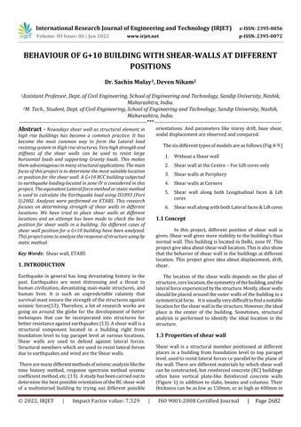
ThemodelingandanalysisisdoneusingETABSsoftware. ThebuildingconsideredfortheanalysisisaResidentialG+10 building. The typical floor plan and elevation of the residentialbuildingisasshowninthefigure2andfigure3.
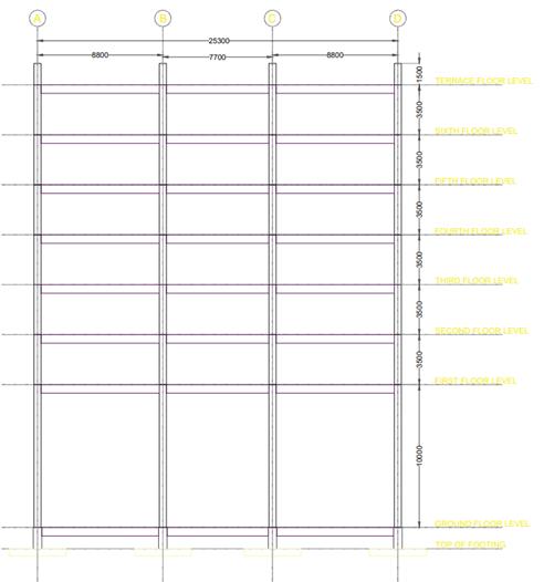
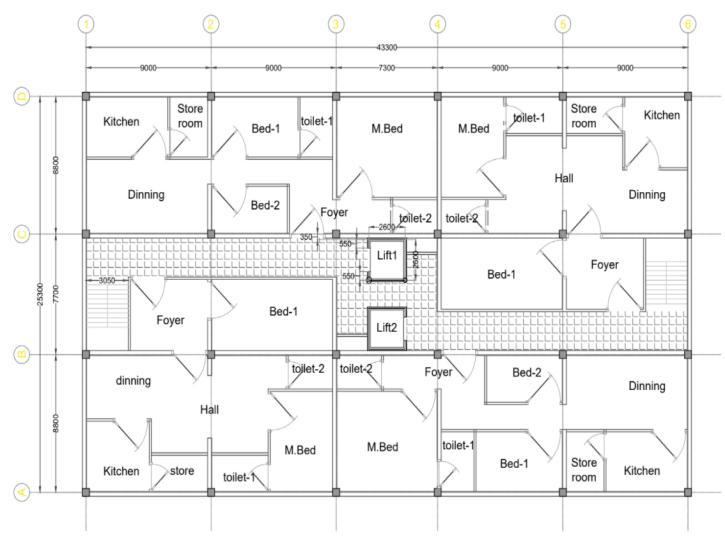
Fig 2:Typicalfloorplan
Fig 3:Elevationofthebuildin
© 2022, IRJET | Impact Factor value: 7.529 | ISO 9001:2008 Certified Journal |
International Research Journal of Engineering and Technology (IRJET) e ISSN: 2395 0056
Volume: 09 Issue: 06 | Jun 2022 www.irjet.net p ISSN: 2395 0072
NumberofStories G+10
1
The building was idealized into a structural frame and modeledinETABSbygeneratingthegrids.Thesixdifferent modelsweremodeledandanalyzedseparately.Thesemodels areasfollows:
Table 3:Buildingdescription
MATERIALSPECIFICATIONS
ElasticModulusofM30concrete 27386.12MPa ElasticModulusofM40concrete 31622.77MPa PoissonsRatioofConcrete 0.2 ElasticModulusofSteel 200000MPa
Table 4:Materialspecification
TYPEOFLOADING
CODE
DeadLoad IS875(Part1):1987 LiveLoad IS875(Part2):1987 WindLoad IS875(Part3):1987 SeismicLoad IS1893(Part1):2016
Table 5:ISCodesused
DESCRIPTION VALUE
ZoneFactor IV 0.1 SoilType Medium II ImportanceFactor I 1 ResponseReductionFactor R 3
Table 6:Seismicparameters
DESCRIPTION VALUE
LocationofBuilding Delhi Purpose ResidentialOccupancy Sub Structure In SituRaftFoundation Super Structure OrdinaryMoment ResistingFrames FloorSlabType Two Wayslabsystem LateralLoad resistingsystem RigidFloorDiaphragmand OMRFwithShearWalls No. Load Combination 1. 2. 3. 4. 5. 6. 7. 8. 9.
BasicWindSpeed 44m/s DesignlifeofStructure(50years) 1 Topographyfactor 1 TerrainCategory 2 ImportanceFactor 1 PressureCoefficientPositive 1.2 PressureCoefficientNegative 0.001
Table 7:Windloadparameters
International Research Journal of Engineering and Technology (IRJET)
e ISSN: 2395 0056
Volume: 09 Issue: 06 | Jun 2022 www.irjet.net p ISSN: 2395 0072
All the six models were analyzed, and the results were generated from ETABS. Before running the analysis, the modelhasbeencheckedforanywarnings.
Storey displacements plotted when Earthquake hits in X direction.Significantstoreydisplacementsareobserved.
Fig 4:Modelcase1
Fig 5:Modelcase2
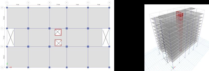
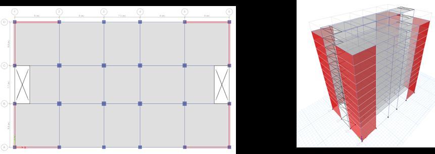
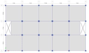
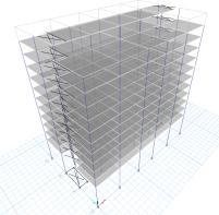
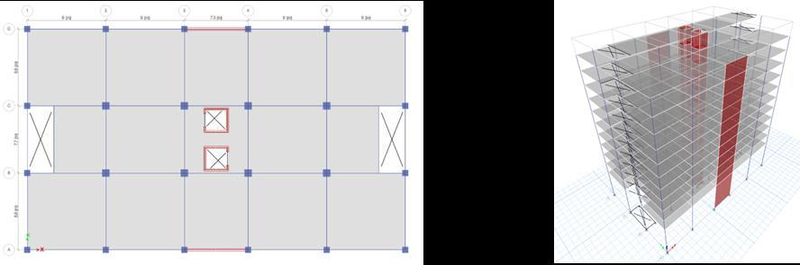
Fig -9:Modelcase6
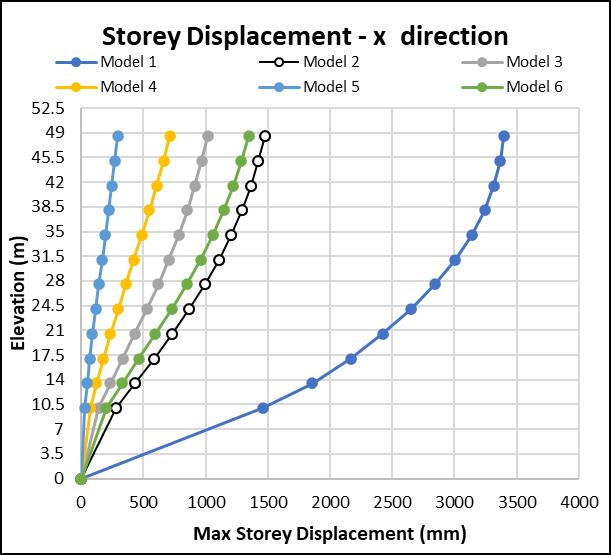
Model 1 having No shear walls tend to show very large displacements. Very small displacements are observed in Model5(Shearwallsatcorners). Model2&4areshowing almostsamestoreydisplacementsinYdirection.Similarly, Model3&6.Thisshowsthatthecontributionoftheshear wallalongX directionisveryless.
Themaxstoreydisplacementisobservedtobesignificantly reduced when compared with the building without shear wall.Morethan50%reductionindisplacementswasnoticed justbyprovidingshearwallsattheliftcores.Maximumof about90%reductionindisplacement wasobservedwhen theshearwallswerelocatedatthecornersofthebuilding. Differentorientationsofshearwallhavebeenstudiedand therespectivereductionwasnotedandcanbeseeninthe bargraph.Althoughwehavegot90%reductionwithoneof theorientations,weneedtocheckwhetheritisoptimum/ economical or not? To know that I have calculated the efficiency of every model considered. The efficiency was calculatedbyMaxstoreydisplacementdividedbythelength ofshearwallprovided.Calculationsshowthatthemaximum efficiencyisshownbythrmodelwiththeshearwallsatthe Liftcoresonly
Fig 6:Modelcase3
Fig 7:Modelcase4
Fig 10:Storeydisplacementinx direction
Fig 8:Modelcase5
International Research Journal of Engineering and Technology (IRJET) e ISSN: 2395 0056
Volume: 09 Issue: 06 | Jun 2022 www.irjet.net p ISSN: 2395 0072
Model 1 give more displacement as compared to other Model,becausethemodeldoesn’thaveshearwalls.Model5 give very less displacement, because shear walls are providedatthecorners.Thisconfigurationisrestrainingthe displacementinalldirectionsmakingthestructureverystiff. The displacements are reduced by almost 50% just by providingshearwallsattheliftcores.
Whereas providing shear walls along longer side of the structureisobservedtobenotveryefficient.Thereasonis quietobviousthattheMomentofInertiaandsothestiffness of the structure is already higher along longer side, providingshearwallsalongthisdirectionmaybeofnouse andonlyincreasingthecostofthestructure.
Infigure13,reductionofstoreydisplacementwithrespect toModel1isgiven.Model5hasshownthemaximumabout 90%reductionwhenshearwallisprovidedatthecorners. Reductionindisplacementmaybeafascinatingnumberbut agoodstructuraldesigncanbeidentifiedbytheefficiencyof the structural components we are providing. And hence plotting the efficiency of each and every configuration consideredisveryimportant.
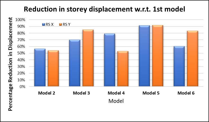
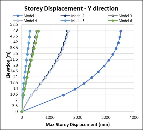
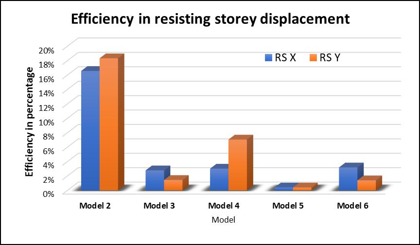
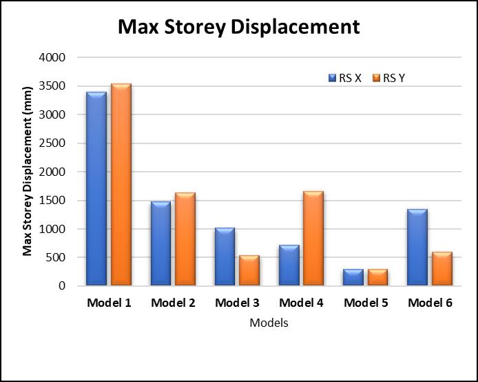
Fig 11:Storeydisplacementiny direction
Fig 13:Reductioninstoreydisplacementw.r.t.first model
Fig 12:Maximumstoreydisplacement
Fig 14:Efficiencyinresistingstoreydisplacement
Shear wall is become an important structural component when it comes to High rise buildings. Provision of shear walls in high rise structures significantly reduce the displacementsandsuppresstheeffectofseismicforcestoo. But, just providing the shear walls is not enough. The location where shear walls have to be provided and the configurationisofimportance.Asastructuralengineer,we shouldalwaystrytomakethedesignssuchthatweareusing lowest possible quantity of concrete and steel in the structure. Not only that but utilizing their strengths and capacitiestothefullest.
International Research Journal of Engineering and Technology (IRJET) e ISSN: 2395 0056
1. Displacementsofthestructurecanbereducedby around 50% just by providing shear wall at the centerofthebuilding.
2. Providingshearwallsatthecornercanbethebest optionwhenitisnotpossibletoprovideshearwalls atthecenter.
3. Shearwallshallbeprovidedalongtheshorteredge ofthestructure.
4. Providing shear walls along longer side of the structuremaynotbeusefulasstructurealreadyhas higherstiffnessalonglongerdirection.
[1] AshrafHabibullah,S.E,“PhysicalObjectBasedAnalysis and Design Modeling of Shear Wall Systems using ETABS”, Computers & Structures, Inc., Berkeley, California
[2] Donthireddy Raja Shekar Reddy, Joshi Sreenivasa Prasad,“TheSeismicAnalysisofMultiStoriedBuilding with Shear Walls of Different Shapes in all Zones”, International Journal of Engineering Research & Technology(IJERT),Vol.8Issue07,July 2019
[3] Gauravi M. Munde, Prof. N. K. Meshram, ‘‘Seismic Analysis of Shear Wall at Different Location on Multi story RCC Building’’ International Journal of Interdisciplinary Innovative Research & Development (IJIIRD)Vol.02Issue01|2017
[4] MaisnamChittankumar,BSSureshChandra,“Analysis of G + 10 Multi story Building using ETABS”, International Journal of Research in Engineering and Science(IJRES),Volume09Issue11ǁ2021ǁPP.74 80
[5] Mindala Rohini, T. Venkat Das, “Seismic Analysis of ResidentialBuildingforDifferentZonesusingETABS”, International Journal of Recent Technology and Engineering(IJRTE),ISSN:2277 3878,Volume 7,Issue 6C2,April2019
[6] Mohd. Aslam, Vishal Kumar, Saurabh Pandey, ‘‘Comparison of Seismic Analysis of Multi storeyed Building by ETABS and Manual Calculation’’ ManTech Publication,Volume2Issue2
[7] Mr.AnkurVaidya,Mr.ShahayajaliSayyed,“AResearch onComparingtheSeismicEffectonShearwallbuilding and Without Shear Wall Building A Review” International Research Journal of Engineering and Technology(IRJET),Volume:05Issue:12|Dec2018
[8] Mr. Basavalingappa, Mr. Anil Kumar B, ‘‘Analysis of High RiseBuildinganditsBehaviorDuetoShearWallat
Different Location and in Different Seismic Zones’’ International Journal of Engineering Research & Technology(IJERT)Vol.9Issue09,September 2020
[9] P. Siva Sankar, Dr. P. Kodanda Rama Rao, ‘‘Static And Dynamic Analysis Of A Multi Storied Building With Shear Walls At Different Locations’’ International Journal of Engineering & Science Research (IJESR) Volume 7Issue:Mar2019
[10] PriyaKewat,KavitaGolghate,‘‘EffectofShearWallsat Different Locations with Varying Thickness in MultistoreyBuildings’’InternationalResearchJournalof EngineeringandTechnology(IRJET)Volume:07Issue: 12|Dec2020
[11] Priyanka Kosare, DeeptiHazari,‘‘Study of Behavior of Multi Story Building with Shear Walls’’ International ResearchJournalofEngineeringandTechnology(IRJET) Volume:06Issue:07|July2019
[12] ShobhaRam,SyedKaleemAZandMohitM,‘‘Effectsof Openings on Different Shapes of Shear Wall in RC Buildings’’CrimsonPublishersVolume3 Issue3
[13] Vijit Sahu, Dr. G.P. Khare, Mr. Dushyant Kumar Sahu, “Behaviorofmultistoreybuildingwithdifferentshear wallarrangementswithandwithoutcentralcrossshear wall”,InternationalResearchJournalofEngineeringand Technology(IRJET),Volume:05Issue:01|Jan 2018
Volume: 09 Issue: 06 | Jun 2022 www.irjet.net p ISSN: 2395 0072 © 2022, IRJET | Impact Factor value: 7.529 | ISO 9001:2008 Certified Journal |