International Research Journal of Engineering and Technology (IRJET) e-ISSN: 2395-0056
Volume: 09 Issue: 06 | June 2022 www.irjet.net p-ISSN: 2395-0072
DESIGN AND ANALYSIS OF HIGH ENTROPY ALLOY SPUR GEAR
Kamalesh.S1, Satishkumar.J2, Dinesh Kumar.R3
1,2,3 Student, Dept. of Mechanical Engineering, Kumaraguru College of Technology, Tamilnadu, India ***
Abstract – Gear and gearbox arrangement play a vital role in the power transmission system of any vehicle. Several types of gear were available. Some of them are Bevel gear, Worm gear, Spur gear, and Helical gear. Of which spur gear is involved in the majority of vehicles and locomotives. The problem with the conventional gear is that the weight of the gear contributes majorly toward the total weight of the vehicle and machine. Design and analysis of spur gear are done with the help of the designing software Catia V5 and analysis software Ansys. Kinematic analysis of designed gear was done theoretically by applying a gear ratio of 1:2. A comparison study of Structural steel gear and High entropy alloy gear was done on the aspects of structural parameters like Stress, Strain, Strain energy, and Deformation. The effect of one of the structural parameters on the other was studied with the help of a graph, and Hooke’s law of stress and strain was verified.
Key Words: High entropy alloy, Weight reduction, Material science, Ansys, Static structural
1. INTRODUCTION
Carbonsteelisoneofthemajorlyusedmaterialsinthefield ofmechanical engineering. Themainpropertiesofcarbon steelwerehightensilestrength,highloadcarryingcapacity, andlowdeformation.Eventhoughithasgoodmechanical properties,themain problemofcarbonsteel wasitspoor corrosion resistance and greater weight. To replace these issues, one of the recent advancements in the material science field is the development of High entropy alloys. These high entropy alloys have similar tensile and load carryingcapacitybuthavegoodcorrosionandlessweight.A studyonCrMnFeCoNihighentropyalloyshowsgoodfatigue strengthandhasamoreexcellentfracturepoint[1].Another study on high entropy alloys Nb25Mo25Ta25W25 and V20Nb20Mo20Ta20W20revealsthatatroomtemperatureyield stress of both the material drops to 30 40% while at the rangeof600oCto1600oCthematerialbehavesefficientlyin terms of yield strength and refractive property [2] CoCrFeNiTiAlx alloy were studied at different molar concentrationsofAluminium,anditrevealsthatthevalueof compressivestressandtensilestressreachesthemaximum value of 2.28GPa [3]. Properties of AlNbTiV high entropy alloy were studied at different temperatures, and it was found to be that the value of tensile strength gradually decreasesfrom1020MPato158Mpawhenthetemperature of the material is increased from 800oC to 1000oC [4] MoNbHfZrTi microstructure and mechanical properties study reveal that the value of tensile strength at room
temperatureisfoundtoliebetween1719Mpaand1575Mpa [5]. AlCoCrFeNi high entropy alloy surface coated with a nitridelayerbythenitridingprocessexhibitsgoodwearand hardnessproperty.ThestudyachievesaVickershardness valueof720HVandawearrateof2.8×10 5 mm3/Nm[6] A spur gear taken from a machine is designed and analysed with the help of CATIA V5 and Ansys software. Graphs requiredforthecomparativeanalysiswereplotted,anddata analysiswasdoneinMicrosoftexcel.
1.1 Selected Materials and Their Properties
Materialsselectedforthestudyarecharacterizedbythree criticalmechanicalpropertiesyieldstrength,density,elastic modulusandPoissonratio.Materialsselectedforthestudy andtheirpropertiesaregiveninTable 1[7]
Table 1: MaterialsandtheirProperties
Material Density (g/cm3) Yield Strength (MPa)
Elastic Modulus (GPa)
Poisson Ratio
EN8Steel 7.85 280 190 0.3
Al80Li5Mg5Zn5Cu 2.9 488 69 0.3
AlCrFeNiMo0.5 6.8 1749 205 0.34
Ti 6Al 4V 4.43 883 110 0.31 Al7075 T6 2.81 505 70 0.32
1.2 Specifications of the spur Gear
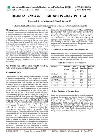
Importantspecificationsthatneedtobeconsideredbefore designing the spur gear are Outside Diameter (OD), Pitch Circle Diameter (PCD), Module (m), Addendum (A), Dedendum (D), Clearance (C), Circular Pitch (CP), Tooth Thickness,FaceWidth,NumberofTeeth(T),InternalHole Diameter/Shaft Diameter (d), Angle Between Two SuccessiveTeeth,TotalDepth(TD),WorkingDepth(WD), DepthofTheGearTooth.Figure 1representstheimageof thegeartakenfromthesimplesix speedgearbox.
© 2022, IRJET | Impact Factor value: 7.529 | ISO 9001:2008 Certified Journal |

Fig 1: Geartakenfromgearbox
1.3. Formulas Used to Calculate Spur Gear Parameters.
Specificationsmeasureddirectlywiththehelpofavernier calliper,screwgaugeandgeartoothvernierwereOutside Diameter, ToothThickness, FaceWidth,Numberof Teeth, Internal Hole Diameter/Shaft Diameter, and Depth of The GearTooth.Otherparametersrequiredtodesignthespur gearwerecalculatedfromtheformulaegiveninTable 2,
Table 2: Formulaetobeused.
PitchCircleDiameter [T×OD/T+2] Module PCD/T CircularPitch π×m Addendum 1×m Clearance 0.157×m(OR)0.25×m
Dedendum Addendum+Clearance
Addendumcirclediameter PCD+Addendum
Dedendumcirclediameter PCD Dedendum
Anglebetweensuccessive teeth 360/T
Totaldepth Addendum+Dedendum Workingdepth Addendum+Dedendum Clearance
Clearancecirclediameter DCD+Clearance
2.Designed Spur Gears Parameters
Apairofspurgearsweredesignedinwhichthelargergear (Wheel)istheonewhichistakenfromthegearboxwhilethe smallerone(pinion)isdesignedentirelybasedonthegear ratio.Astandardgearratioof1:2ismaintainedtodesignthe pinion. The gear ratio of 1:2 represents that the pinion rotatedtwiceforonerevolutionofthewheel.Anassumption ismadetodesignthepinion,i.e.,thewheelistakenasthe input gear while the pinion is taken as the output gear. Expression for the calculating the number of teeth on the pinionisgivenbelow,
N1isthespeedoftheinputgearinRPM.
N2isthespeedoftheoutputgearinRPM.
T1isthenumberofteethininputgear.
T2isthenumberofteethinoutputgear.
For a pair of gears to mesh, the module of both the gears must be the same. All other design parameters required were calculated by keeping the module the same and calculatingthe numberof teethinthepinion.Table 3and Table 4 give the gear wheel and pinion dimensions, respectively.
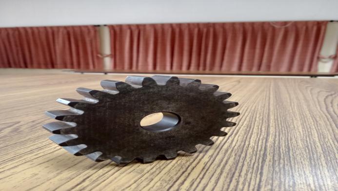
Table-3: Dimensionsofgearwheel
Particulars
Dimension (mm)
OutsideDiameter 120
ToothThickness 6.12 FaceWidth 20 Numberofteeth 22 Internalholediameter 24 Depthofgeartooth 7.14 Pitchcirclediameter 110 Module 5 Addendum 5 Dedendum 6.25 Clearance 1.25 CircularPitch 15.71 Anglebetween successiveteeth (degrees)
16.364
Table 4: DimensionofGearPinion
Particulars
Dimension (mm)
OutsideDiameter 60
ToothThickness 3.06 FaceWidth 20 Numberofteeth 11 Internalholediameter 12 Depthofgeartooth 2.45 Pitchcirclediameter 55 Module 5 Addendum 5 Dedendum 6.25 Clearance 1.25
CircularPitch 15.71 Anglebetween successiveteeth (degrees)
32.727
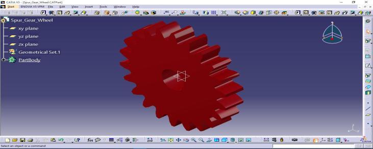
2.1. Modelled Wheel and Pinion
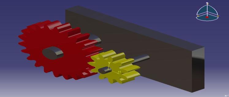
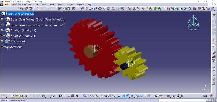
The data obtained from the calculation and table 3 and table 4gearwheelandpinionweredesignedwiththehelp ofmodellinganddraftingsoftwareCATIAV5.Figure 2and Figure 3 represent the 3 Dimensional part models of the Gearwheelandpinion.Figure 4andFigure 5representthe assemblymodelsofgearandpiniontogether,showingthe teeth are in mesh. In Figure 5, a rectangular block is provided,whichmakesitsimilartoagearboxarrangement where the shafts are enclosed in the common box like structure.
3. Static Structural Analysis of Spur Gears
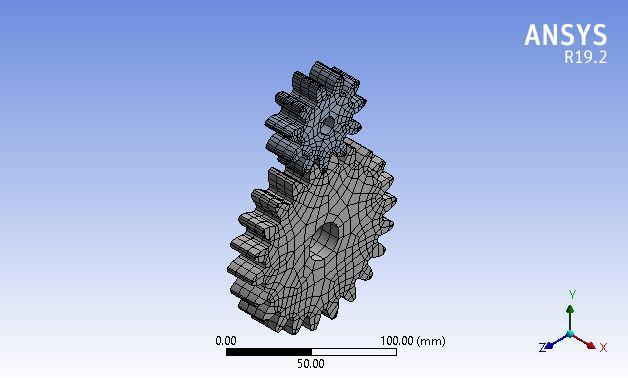
Staticstructuralanalysisisoneofthemostcommonlyused methodsinwhichtheentiremodelisconvertedintosmall elements of finite size. In those small elements, loads and support reactions are applied, and results are calculated. After calculating all the elements' results, they are added together to get the required result. Here, static structural analysis of carbon steel was done for ten different loads starting from 50N mm to 1000N mm, and their correspondingstress,strain,strainenergy,deformation,and volumechangeeffectwasstudied.Forasingleloadof100N mm,allotherHighentropy alloygearswereanalysedand comparedwiththevalueofthesameamountofloadthatis applied in the structural steel. Analytically all these load reactionanalysesweredoneontheanalysissoftwareAnsys. Allthereadingsweretabulatedandpresentedasalineplot usingexcel.Inboth,theanalysisstandardnumberof2106 mesh elements were found. A global coordinate system is maintainedthroughouttheprocess.Figure6representsthe numberofnodesformedonthemodel. Fig
International Research Journal of Engineering and Technology (IRJET) e-ISSN: 2395-0056
3. Applyclockwise(or)anticlockwisemomenttothe largergear.
4. Apply ten different moments and measure all the values, i.e., Stress, Strain, Strain energy, Deformation
Figure7representstheboundaryconditionsappliedforthe analysis.
100 0.68867 1.4317 150 1.5495 2.1475 200 2.7547 2.8634 250 4.3042 3.5792 300 6.1981 4.2951 350 8.4362 5.0109 400 11.019 5.7268 450 13.946 6.4426 500 17.217 7.1585 1000 68.867 14.317
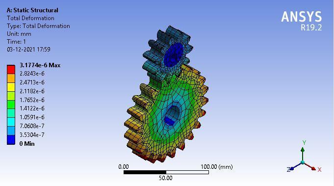
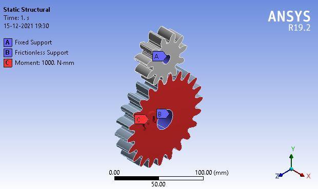
Fig 7: BoundaryConditionforWheelandPinion
4. Results and Discussion
4.1. Structural Analysis of Carbon Steel
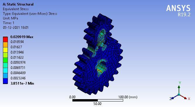
Loadingisgivenasamoment,andthecorrespondingresults are noted and tabulated. Loading starts by applying a momentof50N mmandloadsprogressbyadding50N mm untilthevalue1000N mmisattained.Strain,StrainEnergy, Deformation, and Stress are the main parameters noted. Tables5and6givethedataofappliedloadormomentand itscorrespondinganalysisvaluesregardingstaticstructure. Figure 8,9,10,11representsthestress,deformation,strain energy,andstraindistributioncontourwhenthemomentis appliedonthelargergearwheel
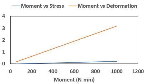
Table 5: LoadvsStressvsDeformation
Load (N mm) Stress (MPa) Deformation (E 5) 50 0.010459 0.15887 100 0.020919 0.31774 150 0.031378 0.4766 200 0.041837 0.63547 250 0.052297 0.79434 300 0.062756 0.95321 350 0.073215 1.1121 400 0.083675 1.2709 450 0.094134 1.4298 500 0.104590 1.5887 1000 0.209190 3.1774
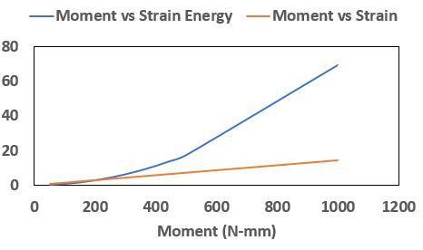
Table 6: LoadvsStrainvsStrainEnergy
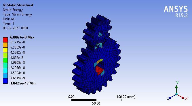
Load (N mm) Strain Energy (10 7 mJ) Strain (10 7 mm/mm) 50 0.17217 0.71585
Fig 8: EquivalentStressContour
Fig 9: Equivalentdeformationcontour
Fig 10: EquivalentStrainEnergyContour
Volume: 09 Issue: 06 | June 2022 www.irjet.net p-ISSN: 2395-0072 © 2022, IRJET | Impact Factor value: 7.529 | ISO 9001:2008 Certified Journal | Page2937
Fig-11: EquivalentStrainContour
Chart 1andChart 2representthegraphicalformatofTable 4andTable 5,inwhichchart 1establishestherelationship ofthemomentwithstressanddeformation.Incontrast,the chart r establishes the relationship of the moment with strainenergyandstrain.Thechartsshowthatthevalueof stress, strain, strain energy, and deformation is directly proportionaltothevalueoftheappliedmoment.Therefore, givenmaterialobeysHooke’slawwhichstatesthatstressis directly proportional to the strain within the given elastic limits.SinceANSYSdoesnotgivethefractureresultofthe analysismaximumof1000N mmcanbeappliedtothegiven pairofspurgearsastheelasticpoint,andbeyondthisvalue, plasticdeformationoccurs.
4.2. Comparison with High Entropy Alloy Gears
The maximum load that the designed spur gear assembly withstandis1000N mm.Therefore,forthemaximumloadof 1000N mm,Highentropyalloysselectedforthestudyare appliedtothegivenspurgearassemblybysimplychanging the material's properties in the Ansys workbench. The requiredcalculatedvaluesarenotedandpresentedinTable 7andTable8.Acomparisonof those data wasmade,and relevantresultsweredrawn.
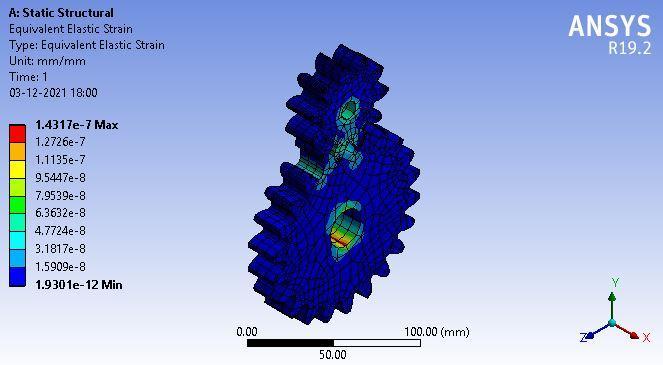
Table-7: Material,Mass,Deformation,
StrainComparison
Materials Mass (Kg) Deformation (10 5 mm) Strain (10 6)
Structured Steel (or)EN8Steel 1.7314 3.177 1.4317
Al80Li5Mg5Zn5Cu 6.3962 E 4 9.2098 4.1498
AlCrFeNiMo0.5 1.4998 3.106 1.3543
Ti 6Al 4V 0.61977 9.091 4.0294 Al7075 T6 0.97707 5.7819 2.5838
Table 8: Material,Stress,StrainEnergyComparison
Materials Stress(MPa) StrainEnergy (10 5 mJ)
Structured Steel (or)EN8Steel 0.20919 0.68867
Al80Li5Mg5Zn5Cu 0.20919 1.9962
AlCrFeNiMo0.5 0.21012 0.67104
Ti 6Al 4V 0.20967 1.9664 Al7075 T6 0.20943 1.2518
From the Table 7 and Table 8, the following results were derived,
Chart 1: MomentvsStressandMomentvsDeformation
1.Itisinferredthatthematerial“Al Cr Fe Ni Mo0.5”replaces theconventionalsteelalloymostlikelybecauseitreduces the weight of the gear by “13.37%” and it has the nearly identical value of stress, strain, strain energy and deformation.
2 Thesecondmostmaterialthatcanreplaceconventional steelis“Ti Al V”becauseitreducestheweightofthegearby “43.56%”. However, the strain, strain energy and strain increasebyaconsiderableamountwhilethestressremains nearlyequalvalue.
3 Theremaining twomaterials,“Ti Al V”and“Al T6”, are notpracticallyfeasibleones.
Chart 2: MomentvsStrainenergyandMomentvsStrain
5. CONCLUSION
Aspurgearistakenfromthegearbox,anditisdesignedwith thehelpofdesigningsoftwareCatiaV5.Itsstaticstructural
International Research Journal of Engineering and Technology (IRJET) e-ISSN: 2395-0056
Volume: 09 Issue: 06 | June 2022 www.irjet.net p-ISSN: 2395-0072
analysiswasdoneontheanalysissoftwareAnsys.Various structuralparameterslikeStress,Strain,Strainenergy,and deformationwerestudiedelaboratelyforcarbonsteel,and theirdatawerepresentedintheformofchartsandtables. Afterfindingthemaximumloadvalueforcarbonsteelgear, thehighentropyalloygearwasanalysedforthatparticular maximum load. Results of high entropy alloy and carbon steelwerecompared,anditwasfoundtobethat“Al Cr Fe Ni Mo0.5” and “Ti Al V” replaced the conventional carbon steel by reducing its weight to 13.37% and 43.56%, respectivelywithoutsignificantvariationsinotherstructural parameters
REFERENCES
[1] Z. Li, S. Zhao, R. O. Ritchie, and M. A. Meyers, “Mechanicalpropertiesofhigh entropyalloyswith emphasisonface centeredcubicalloys,” Prog.Mater. Sci., vol. 102, pp. 296 345, 2019, doi: 10.1016/j.pmatsci.2018.12.003.
[2] O.N.Senkov,G.B.Wilks,J.M.Scott,andD.B.Miracle, “MechanicalpropertiesofNb25Mo25Ta25W25and V20Nb20Mo 20Ta20W20 refractory high entropy alloys,” Intermetallics, vol. 19, no. 5, pp. 698 706, 2011,doi:10.1016/j.intermet.2011.01.004.
[3] K. B. Zhang et al., “Microstructure and mechanical properties of CoCrFeNiTiAlx high entropy alloys,” Mater. Sci. Eng. A, vol. 508, no. 1 2, pp. 214 219, 2009,doi:10.1016/j.msea.2008.12.053.
[4] N.D.Stepanov,D.G.Shaysultanov,G.A.Salishchev, and M. A. Tikhonovsky, “Structure and mechanical properties of a light weight AlNbTiV high entropy alloy,” Mater. Lett.,vol.142,pp.153 155,2015,doi: 10.1016/j.matlet.2014.11.162.
[5] N. N. Guo et al., “Microstructure and mechanical properties of refractory MoNbHfZrTi high entropy alloy,” Mater. Des., vol. 81, pp. 87 94, 2015, doi: 10.1016/j.matdes.2015.05.019.
[6] Y.Wang,Y.Yang,H.Yang,M.Zhang,S.Ma,andJ.Qiao, “Microstructure and wear properties of nitrided AlCoCrFeNihigh entropyalloy,” Mater. Chem. Phys., vol. 210, pp. 233 239, 2018, doi: 10.1016/j.matchemphys.2017.05.029.
[7] S.Rajesh,P.Marimuthu,andP.DineshBabu,“Contact and bending load capacity enhancement through highentropyalloys,” IOP Conf. Ser. Mater. Sci. Eng., vol. 624, no. 1, 2019, doi: 10.1088/1757 899X/624/1/012029.
2022, IRJET | Impact Factor value: 7.529 | ISO 9001:2008 Certified Journal |