International Research Journal of Engineering and Technology (IRJET) e ISSN:2395 0056

Volume: 09 Issue: 06 | June 2022 www.irjet.net p ISSN:2395 0072
International Research Journal of Engineering and Technology (IRJET) e ISSN:2395 0056
Volume: 09 Issue: 06 | June 2022 www.irjet.net p ISSN:2395 0072
Pranjal A.Patil (1)
Student at Department of Electrical Engineering
DYPTC Talsande, Kolhapur Maharashtra, India
Meenal P.Karande Patil(4)
Student at Department of Electrical Engineering
DYPTC Talsande,Kolhapur Maharashtra, india
Pratiksha P.Patil (2)
Student at Department of Electrical Engineering
DYPTC Talsande, Kolhapur Maharashtra, India Mansi A.Shendge(5) Student at Department of Electrical Engineering
DYPTC Talsande, Kolhapur Maharashtra, India
ABSTRACT This project is done for monitoring and controlling of three phase induction motor. It is necessary to monitoring the condition of induction motor to get better efficiency and output. Hence, we monitoring the condition of motor such as speed, direction, voltage, current, frequency and temperature. In addition to this we use modern technology which is GSM model(Global Sim Modulation) and Theft Detection technique. For Protection of induction Motor Microcontroller based system is proposed which plays major role than other technique.
Keywords: PIC16F886 microcontroller, SIM800C, GSM, Induction Motor, LCD
Circuit Condition monitoring means the process which is done before any failure occur induction motor. Induction motor is reliable ,robust ,simple in construction and less expensive.Duetothisitisusedinindustrialapplications.
Thisprojectisdoneformonitoringandcontrollingofthree phase induction motor . It is necessary to monitoring the condition of induction motor to get better efficiency and output.Hence,wemonitoringtheconditionof motorsuch as speed, direction, voltage, current, frequency and temperature.Inadditiontothisweusemoderntechnology which is GSM model(Global Sim Modulation) and Theft Detection technique. For Protection of induction Motor Microcontroller based system is proposed. Various types
**
Rutuja D.Zende (3) Student at Department of Electrical Engineering
DYPTC Talsande, Kolhapur Maharashtra, India
Mr. Aniket C.Daiv Assistant Professor At Electrical Department
DYPTC Talsande, Kolhapur Maharashtra, India
of motor condition is monitored by using microcontroller which plays major role than other technique. one more advantageofthistechniqueis,itrequirelessinteractionof human body. Microcontroller based protection is better than any other computer and classical techniques. So we usePIC16F886microcontroller.
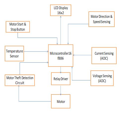
Fig1SystemArchitecture
International Research Journal of Engineering and Technology (IRJET) e ISSN:2395 0056
Volume: 09 Issue: 06 | June 2022 www.irjet.net p ISSN:2395 0072
LCD interfacing with microcontroller LCDconsist of16 pinsoutofthem8pinsaredatalinesfromD0 D7buthere is4bit modeisusedsofromD4 D7datalinesisconnected toRC0 RC3i.e.Pin11 Pn14ofPICmicrocontroller3pinsis a control pinsi.e.RS,R/W &E.RSisregisterselecting pin whichisconnectedtoRC4Pin15,R/Wreadandwritepin andEis a enable pin Which isconnected to RC5pin16 of PICMicrocontrollerandGNDisgroundandVCCforpower and resistor is connected to contrast control pin to increase and decrease brightness of display and LCD positiveandLCDnegativeisforbacklightLED’s
LM35 interfacing with microcontroller-LM35 TemperatureSensorisused3nolegofLM35is connected to ground,1 no leg is connected to5v but there is one 1k resistor of strong pull up used. 2 no pin is connected to outputand3nopinisconnectedtoGNDandoutputofthis isgiventoADCTheftDetectionCircuitinterfacingwithPIC Microcontroller pinofPIC Microcontroller i.e. pin no 7 in this analog input is converted into digital output. Coil having particular resistance which is 30 ohm, 15 ohm, or below30ohm.Wehavemeasureresistanceofcoilwhichis 30 ohm which is measured with the help of microcontroller through givingsquare wave pulse Voltage drop is measured through V=IR formula R15 IS 100K resistor and input of this is given to RA pin of PIC Microcontroller theft detection part is same as a relay section
Voltage ADC Circuit interfacing with PIC Microcontroller 1 Megha ohm resistor is used and input gives440vAtJ3Rphaseisconnectedtopin1andBphase is connected to pin2. R12 and R11 is used as voltage divider analog voltage is obtained which is given to ADC pin of PIC Microcontroller. in which analog input is converted into digital output.By voltage circuit frequency issensedandoutputofvoltagecircuitisACbecausebridge isabsent
Current ADC Circuit interfacing with PIC Microcontroller At J1 i.e. between pin 1and pin 2 we connect currenttransformerand DiodeD15,D6,D7And D8 are bridge rectifier which convert AC to DC.C10 is 100microFarad capacitor is used.R1 And R2 220 ohm resistorisusedwhichworkasvoltagedividerandR3is10 k which is pull down resistor when CT is not connected. Inputofthis is givento ADC pinofPIC Microcontroller. in whichanaloginputisconvertedintodigitaloutput.
Proximity Sensor Circuit interfacing with PIC Microcontroller PNP Proximity sensor is used. It has 3 pinspin1 isconnectedto5vi.e.vcc,2pinisconnectedto
GND,3pin isPNPoutputWhenobstaclepartispresent at frontofitthenPNPisactivatedInthisR17AndR18isused as pull up. Pull up means when pin is not connected to anythingthenitgives+5voutput(VCC).
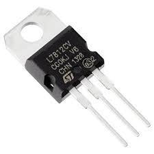
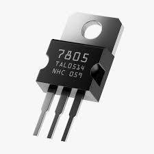
Power Supply Circuit In power supply D1,D2,D3 And D4 (1N4007) Diodes is used.C1capacitor470microfarad 35v is connected to input of 7812 to maintain voltage7812 whichgives12vregulatedsupply
7805whichgives5vregulated supplyForpositivesupply weuse 78series and for negative we use 79 series. Inthis we connect filter capacitor C2 And C8 are 4,17& 10 microfaradcapacitors.
Diodes is used as bridge (full wave bridge) Rectifier input of this given to input of 7812 which gives 12 v At J2 transformerisconnectedbecauseitrequire18vsupply
SIM800C & GSM Circuit interfacing with PIC Microcontroller For sim and microcontroller communication UART protocol is used. UART means universalasynchronous receiver transmitter. It consist of simcardholderinwhich51ohmresistorisuseditdirectly connectedtoSIM800cICCapacitorusedinpikofarad,high pass filter is used. Maximum voltage require is 4.4 v and minimumvoltageis3.1vWegivesoperatingvoltagerange 3.3to4.1vtomanage4.1vseparatepowersupplyisused.
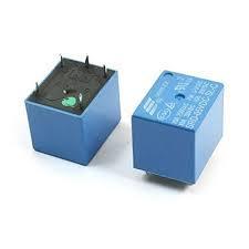
Relay Circuit interfacing with PIC Microcontroller12v/5ARelayisusedtransistor(BC547)(NPN).Baseofthe BC547 is connected to the digital pin of the microcontrollerthrough14res.If5visprovidedtobaseof theBc547Frommicrothencoil(2)issinkedtotheground so voltagebetweencoil1andcoil2becomes12vandrelay commontoNCPingetsShorted.R26isconnectedtopin28 i.e. RB7 pin of PIC Microcontroller which gives digital output i.e. 0 or 5vBC547 has 3 pins base emitter and collector if we give voltage more than 0.7 v to base then transistor is activated. And current start flowing from collectorto emitter i.e. pin1 3 whenground connected to relay,relaystartshencemagneticcoilispresentinrelayis activated and normally close which becomes normally open contact. Here we are using two relay because in starterthereislink ispresenthencewedisconnectlinkin starter and we use relay to start and stop whenever we need. And second rely work as a starter andthis relay is connectedtoPICMicrocontroller.
International Research Journal of Engineering and Technology (IRJET) e ISSN:2395 0056
Volume: 09 Issue: 06 | June 2022 www.irjet.net p ISSN:2395 0072
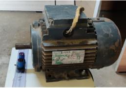
In this project we are using 3phase 415v, 2820 RPM , 0.75H.P ,2.0A star connected Induction motor is used because it is simple, robust and less expensive and it is widelyused inindustry.
Relay used here is 12 v/ 5amp. Coil pin 1 of the relay is connected 12v directly and coil pin 2 is connected to the collectorofthetransistor(BC547)NPN.BaseoftheBC547 is connected to the digital pin of the microcontroller through 1K resistor. If 5v is provided to base of the BC547from microcontroller then coil 2 is sinked to the ground so voltage between coil 1 and coil 2 becomes 12v andrelaycommontoNCpingetsshorted.
7812 AND 7805 Voltage Regulator is used in our project 7812 is used for 12 v supply and 7805 is used for 5v supply.Werequirepositivesupplyhenceweusedhere78 seriesifwerequirenegativesupplythen79seriesisused.
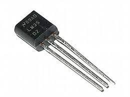
ForTemperaturesensingweareusingLM35Temperature Sensor. Because output of this is an analog signal is proportional to the temperature which is instantaneous LM35doesnotrequireanyexternalcalibration.
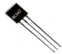
BC547 NPN Transistor has two working states forward biased and reverse biased. In forward biased to allowing current pass through the collector and emitter is connectedtoitandinreversebiasedthistransistorworks asaopenswitchandcurrentisnotflowingthroughit.
Wehavemeasuredpulsesusingproximitysensoroverone second time period. So to convert it to RPM we have multipliedthecountwegotfromsensorby60
Countx60=RPMRev/Min
International Research Journal of Engineering and Technology (IRJET) e ISSN:2395 0056
Volume: 09 Issue: 06 | June 2022 www.irjet.net p ISSN:2395 0072
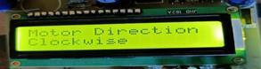
Secondproximitysensoris usedto determine direction of themotor.Ifsensor1isleadingthendirectionofmotoris clockwise and if sensor 1is lagging behind the sensor 2 thendirectionofmotorisanticlockwise.
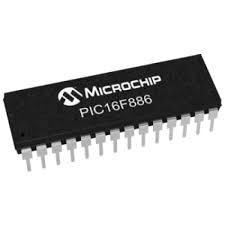
This type of microcontroller is easy for programming . It has 28 input and output pins. Its features is 256 bytes of EEPROMdatamemory.Itconsistof10BitAnalogtoDigital Convertors.
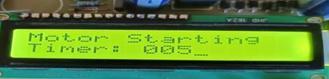
Aftergivingpowersupplythroughrelaytomotormotor willstartafter005sectimedelay.
After2secofdelaymotorisconnectedwilldisplayedon LCD
After 3 sec of delay direction of motor will displayed on LCD
After2secofdelaytemperatureisdisplayedonLCD

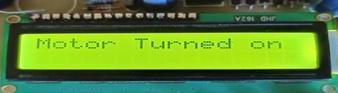
When we give power supply then their will be 30 sec starting delay motor will turn ON then message will displayonLCD.
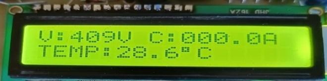
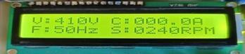
After 2sec of delay voltage, current, frequency, speed is displayedonLCD
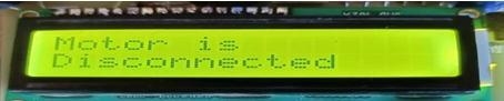
Whenwireconnectionisdisconnectedoranyonetryingto theftthemotorbycuttingcablethenitwillshownonLCD displaythatmotorisdisconnected
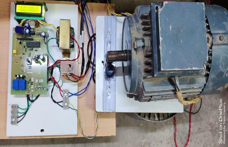
Fig12Motorconnected
International Research Journal of Engineering and Technology (IRJET) e ISSN:2395 0056
Volume: 09 Issue: 06 | June 2022 www.irjet.net p ISSN:2395 0072
In this paper cheaper and simple scheme to start and control the induction motors using microcontroller is successfully explained. We can remotely access the motor using microcontroller. This project has prepared for controlling , monitoring and theft detection circuit for 3 phase induction motor .This circuit can ON and OFF the motor through CALL by mobile. LCD display and GSM module is interfaced with motor so every start , stop condition of induction motor is displayed on LCD module aswellascallissendtouser.
Availabilitymore
Wecancontrolthedeviceeasilybysendingsmsand signals.
More effective.
Cheaper costandeasytoexchange.
High accuracy
Whenmanuallyoperatedtherearemore chancesoferrorssoautomationhelpsinless humanerror.
Itisreliableasitisautomated
Three Phase supply is not easily available to normal consumers.
Duetoincreaseinheatmotorwindingwillburned.
Expansion of this project is we can use current settingscheme.
Whentemperatureisexceedthenmotorwillburnto preventthisdamagethenwecangivespecific cutoff.
[1] GSM module for wireless radiation monitoring system via SMS Nur Aira Abd Rahman,Noor Hisyam Ibrahim,Lojius Lombigit, Azraf Azman,Zainudin jaafar Nor Arymaswati Abdullah, GlamHadzirPataiMohamad
[2] ConditionMonitoringof3 ϕA.CInductionMotor Using PLC PraveenKumar Shukla, Ankur Namdeo, Abhishek Dixit
[3] Microcontroller based fault detection and protection system for induction motor Rupali M Shivpuje,MrSwapnilDPatil
[4] Induction Motor Condition Monitoring And Controlling Based On IOT Seenivasan V1,Ponkumar K1 ,Venkatraman R1, JeslindrusilanesamalarJ2
[5] Control and Monitoring of 3 PhaseInduction Motor Using PLC Piyush Ahuja, Rajiv Kumar, KumarDhiraj.”