International Research Journal of Engineering and Technology (IRJET) e ISSN: 2395 0056

Volume: 09 Issue: 06 | Jun 2022 www.irjet.net p ISSN: 2395 0072
International Research Journal of Engineering and Technology (IRJET) e ISSN: 2395 0056
Volume: 09 Issue: 06 | Jun 2022 www.irjet.net p ISSN: 2395 0072
Asna K A1 , Lakshmi S Anil2
1PG student, Dept. of Civil Engineering, KMEA Engineering College, Kerala, India
2Assistant Professor, Dept of Civil Engineering, KMEA Engineering College, Kerala, India ***
Abstract - Bubble deck slabs have theunusualpropertyof reducing concrete in the slab’s tension zone, lowering slab's weight, which leads to reduction in the size of variouselements such as columns, beams, and footings. In this study, punching shear capacity of the slab was estimated using ANSYS WORKBENCH2021.Toreducesheardamage,CFSwasprovided around the vicinity of column and it was evaluated in different arrangements. The balls in the bubble deck slab are made of High Density Poly Ethylene (HDPE). Bubble deck slab is environmental friendly and reduces carbon emission. When compared to typical concrete slabs, bubble deck slab provides a number of advantages: low total cost, improved structural efficiency, reduced building time and green technology.
A Bubble deck slab floor can provide the requisite load bearing capacity at a small thickness, resulting in saving 40 50 % of the material consumption in the floor construction. In this study, the main objective was to analyze the punching shear behavior of the bubble deck slab with staggered arrangement of balls. Also, the staggered bubble deck slabwas strengthened by implanting CFS (cold form steel) and estimating its improvement in shear capacity.
Key Words: Bubble deck slab, Staggered arrangement, Lateral load, HDPE, ANSYS WORKBENCH, CFS.
Inbuildingconstructions,slabisaveryimportantstructural elementtomakeaspaceandisoneofthelargest element consumingconcrete.Whenitcomestohorizontalslabs,the biggest problem with concrete structures is their hefty weight,whichreducestheirspan[1].Therefore,weemploy bubbles in the slab to reduce its self weight and increase stability.Thisisatechniqueofalmosteliminatingconcrete fromthetensionzone,whichdoesnotplayanystructural purpose,thusreducingthestructuraldeadweight.Voidsare madeusingballs,whicharemadeofwasteplasticmaterial and referred as High density polyethylene balls. They are hollowandlighterinweight.Theconcreteintheslabisnot completelyusedaspertheresearchconducted.Theconcrete which is placed in tension zone is unspecified to carry no loadandhenceitisidle[2]
Therefore,aportionofthisunusedconcretecanbereplaced inanyfashionbyvoidformers,whichdonothingmorethan produce voids. The void formers can be of any shape and
material.Usingrecycledplasticasvoidformerswilllessen theimpactontheenvironment.Thematerialdoesnotreact chemicallywiththeconcreteorthereinforcement,ithasno porosity,enoughrigidityandstrengthtotakeovertheloads
Tostudythepunchingshearperformanceofbubble deckslabinstaggeredarrangement.
To strengthen and improve the punching shear capacityofbubbledeckslabusingCFSimplanting andfindtheeffectivecapacity.
Inthisstudy,themajorgoal wastoimprovethepunching shearcapacityofthebubbledeckslab.Thebubbledeckslab with rectangular arrangement (RA) and staggered arrangement(SA)wascomparedtofindtheeffectiveshear capacity The bubble deck slab was strengthened by implanting CFS. The CFS was implanted in various arrays andtheeffectivearrangementwasestimated.TheCFSwas implantednearthejointofslabandcolumn.TheCFSisathin platewithprovisionsontheflatsurfacetogetproperbond with the slab. The complete analysis was performed in ANSYSWORKBENCH.
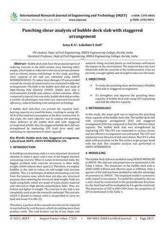
ThebubbledeckslabwasmodeledusingDESIGNMODELER inANSYS.Theslabsizeandpropertiesarementionedinthe Table 1 below. The dimension of the bubble deck slab is 2000×2000×230mmandeffectivespanis1900mm.Onlya quarteroftheslabhasbeenmodeledtotaketheadvantage ofsymmetryin‘ANSYS’. Theemployedmodelissymmetric withrespecttotwoplanes. Tomodelthesymmetry,faceon xandzmustbeconstrainedintheperpendiculardirection. So,thefinalloadwillbemultipliedby4togetthetotalload. ThedimensionofCFSis600×100×3mm.thepropertiesof CFSismentionedintheTable1.
International Research Journal of Engineering and Technology (IRJET) e ISSN: 2395 0056
Volume: 09 Issue: 06 | Jun 2022 www.irjet.net p ISSN: 2395 0072
Table 1: Propertiesofcomponents.
Concrete
Young’smodulus=23734MPa Poisson’sratio=0.2
Compressivestrength=25.5MPa Tensilestrength=3.11MPa
Steel 12mmdia
Young’smodulus=2×10⁵MPa Poisson’sratio=0.3 Yieldstrength=568MPa
16mmdia
Young’smodulus=2×10⁵MPa Poisson’sratio=0.3 Yieldstrength=569MPa
6mmdia
Young’smodulus=2×10⁵MPa Poisson’sratio=0.3 Yieldstrength=466MPa
HDPE
Young’smodulus=1000MPa Poisson’sratio=0.3
Young’smodulus=2×10⁵MPa Poisson’sratio=0.3 Yieldstrength=546MPa
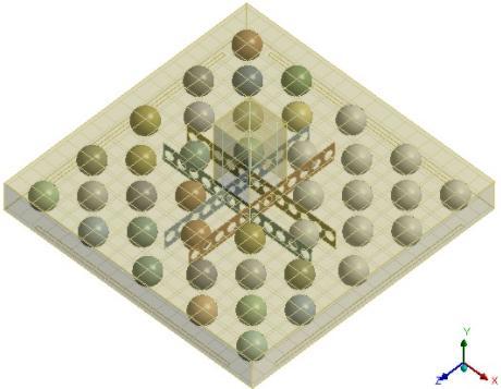
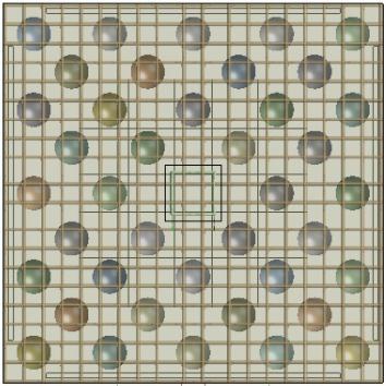
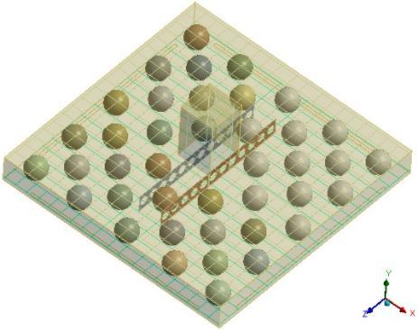
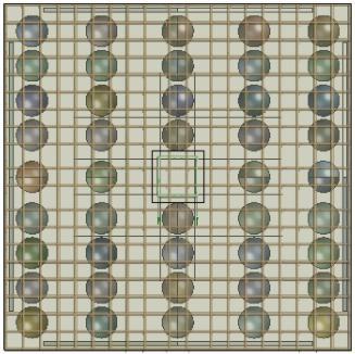
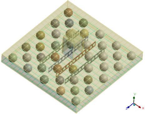
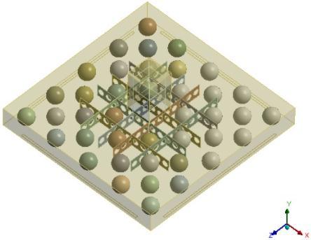
Fig1,2,3,4,5,6,representsthedifferentmodelofbubble deck slab in SA with and without CFS arrays. The CFS provided in different arrays like one row in one direction (1R1D),onerawintwodirections(1R2D),tworowsinone direction(2R1D),tworowsintwodirections(2R2D).
Fig
Fig 4:BubbledeckslabinSAwithCFSin1R2D.
Fig 1:BubbledeckslabinRA
International Research Journal of Engineering and Technology (IRJET) e ISSN: 2395 0056
Volume: 09 Issue: 06 | Jun 2022 www.irjet.net p ISSN: 2395 0072
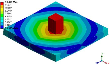

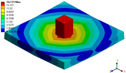
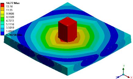
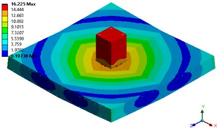
Allthemodelsweresubjectedtopunchingshearanalysis Fig 8, 9, 10, 11, 12, 13 represent the deformation diagram of differentbubbledeckslabmodelsfromANSYS.
Fig 5:BubbledeckslabinSAwithCFSin2R1D.
Fig 6:BubbledeckslabinSAwithCFSin2R2D.
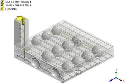
Theslabissimplysupportedon4sides.Theexternalloadis applied over the column following the same procedure as usedintheexperimentalwork.Thisloadwasequallyshared byallnodeswhicharelocatedatthetopsurfaceofactionof thecolumn.Theboundaryconditionandtheloadingdiagram is same for all models. The Fig 7 represents the loading diagram.
Fig 8:ThetotaldeformationofbubbledeckslabinRA.
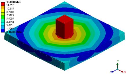
Fig 9:ThetotaldeformationofbubbledeckslabinSA.
Fig 10:Thetotaldeformationofbubbledeckslabin SAwithCFSin1R1D.
Fig 7:Loadingdiagram
International Research Journal of Engineering and Technology (IRJET) e ISSN: 2395 0056
percentage increase in shear capacity of bubble deck slab withandwithoutCFS.Itshowsthattheslabwith2R2Dhas moreshearcapacitythanotherarraysofCFS.
Table 2:ComparisonofPercentageincreaseinshear capacityofbubbledeckslabinRAandSA
Components Deformation (mm) Load (kN) %of increase
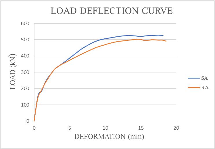
SA 13.09 525.29 4.48 RA 14.51 503.36 1.00
Fig 11:ThetotaldeformationofbubbledeckslabinSA withCFSin1R2D.
Table 3:ComparisonofPercentageincreaseinshear capacityofbubbledeckinSAwithandwithoutCFS.
Components Deformation (mm) Load (kN) %of increase
SA 13.09 525.92 4.48
1R1D 13.44 571.64 8.69 1R2D 14.73 619.64 17.82 2R1D 14.77 587.52 11.71 2R2D 16.23 635.64 20.86
Fig 12:ThetotaldeformationofbubbledeckslabinSA withCFSin2R1D
Fig 13:ThetotaldeformationofbubbledeckslabinSA withCFSin2R2D
The Table 2 represents the comparison of percentage increaseinshearcapacityofRAandSAbubbledeckslab.It showsthatSAbubbledeckhasmoreshearcapacitythanRA bubble deck slab. Table 3 represents the comparison of
Chart -1:LoaddeflectiongraphofSAandRAbubbledeck slab.
Volume: 09 Issue: 06 | Jun 2022 www.irjet.net p ISSN: 2395 0072 © 2022, IRJET | Impact Factor value: 7.529 | ISO 9001:2008 Certified Journal
International Research Journal of Engineering and Technology (IRJET) e ISSN: 2395 0056
[1] Devang M. Sarvaiya and Prof Dipak K. Jivani ,“An experimentalstudyonsphericalvoidedslab”,Journalof EmergingTechnologiesandInnovativeResearch,Vol4, Issue04,2017,2349 5162.
[2] AbhishekR.PandharipandeandN.J.Pathak,“Analytical and Experimental Investigation on Voided Slab”, Internationaljournalofscientific&technologyresearch, Vol8,Issue08,2019,2277 8616.
[3] Sanket Bejgamwar and Aditya Kate, “Structural behaviourofbubbledeckslab”,InternationalResearch Journal ofEngineeringand Technology(IRJET), Vol7, issue5,2020,pp.2395 0072.
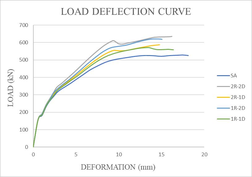
Chart -2:Loaddeflectiongraphofbubbledeckslabwith andwithoutCFS.
TheChart1representstheloaddeflectioncurveof bubble deck slab in RA and SA. The Chart 2 represents the load deflectioncurveofbubbledeckslabinSAwithandwithout CFS.
Inthisstudy,thearrangementofbubbledeckslabischanged tostaggeredarrangement,andthepunchingshearcapacity isestimated.Nowtochecktheperformanceofbubbledeck slab in staggered arrangement in punching shear, need to perform the same in a bubble deck slab in rectangular arrangementwithminimumnumbersofballs.Alsoanalyzing thestaggeredbubbledeckslabwithandwithoutCFS,and then identifying the arrangement with effective shear capacity.
Theconclusionsareasfollows:
Thebubbledeckslabinstaggeredarrangementhas 4% increase in shear capacity and bubble deck slab in rectangular arrangement has only 1% increaseinshearcapacity.
[4] Joo HongChungaandBaek IlBaea,“Evaluationof punchingshearstrengthofvoidedslabsconsidering theeffectoftheratiob0/d”,ElsevierLtd.,Vol164,pp. 2018,70 81.
[5] Nazar K. Oukaili a and Hammad D. Merie, “CFRP strengthening efficiency on enhancement punching shear resistance of RC bubbled slabs with openings”, ElsevierLtd.,Vol15,2021,pp.2214 5095.
[6] LumaFadhil Hussein and Alaa Ali Salman Al Taai, “SustainabilityAchievedbyUsingVoidedSlabSystem”, 2ndInternationalConferenceonMaterialsEngineering &Science,Vol2213,2020,pp.020071 1 020071 7.
[7] SnehalKitture1andNakulKabra,“Experimentalstudy onvoidedbiaxialslabanditsapplications”,International JournalofTrendinScientificResearchandDevelopment (IJTSRD),Vol2,Issue1,2017,pp.2456 6470.
[8] MrYadavJaideepPurushottamandProfTambeYogesh Hemantkumar, “Analytical study of solid flat slab and voided slab using ANSYS Workbench.”, International ResearchJournalofEngineeringandTechnology,Vol3, Issue10,2016,pp.2395 0072.
ThedifferenceinCFSarrangementgivesdifferent results:
Theslabwith1R1Dhas8.69%incrementinshear capacity, the slab with 1R2D has 17.82% incrementinshearcapacity,theslabwith2R1D has11.71%incrementinshearcapacity,theslab with 2R2D has 20.86% increment in the shear capacity.
[9] Joo Hong Chung and Hyung Suk Jung, “Two Way Flexural Behavior of Donut Type Voided Slabs”, International Journal of Concrete Structures and Materials,2018,pp.1976 0485.
[10] MohammedSaifulla,M.A.Azeem,“ComparativeSeismic PerformanceofaConventionalSlabandFlatSlabovera Bubble Deck Slab”, International Journal of Emerging TechnologyandAdvancedEngineering,Vol7,Issue11, 2017,pp.2250 2459.
The bubble deck slab in staggered arrangement with CFS has more shear capacity than those withoutCFS.
[11] Junbo Chen, Jiong Yi Zhu and Tak Ming Chan, “Experimental and numerical investigation on stub column behaviour of cold formed octagonal hollow sections”,ElsevierLtd.,Vol214,2020,pp.0141 0296.
Volume: 09 Issue: 06 | Jun 2022 www.irjet.net p ISSN: 2395 0072 © 2022, IRJET | Impact Factor value: 7.529 | ISO 9001:2008 Certified Journal | Page2819
International Research Journal of Engineering and Technology (IRJET) e ISSN: 2395 0056
Volume: 09 Issue: 06 | Jun 2022 www.irjet.net p ISSN: 2395 0072
[12] https://www.plasticballs.com/plastic balls high density polyethylene.html
[13] https://designerdata.nl/materials/plastics/thermo plastics/high density polyetheen
[14] https://en.wikipedia.org/wiki/Finite_element_method
[15] https://en.wikipedia.org/wiki/Ansys
© 2022, IRJET | Impact Factor value: 7.529 | ISO 9001:2008 Certified Journal | Page2820