International Research Journal of Engineering and Technology (IRJET) e ISSN: 2395 0056

Volume: 09 Issue: 06 | June 2022 www.irjet.net p ISSN: 2395 0072
International Research Journal of Engineering and Technology (IRJET) e ISSN: 2395 0056
Volume: 09 Issue: 06 | June 2022 www.irjet.net p ISSN: 2395 0072
Titas Bhaumik1 , Sumangal Bhaumik2, Surajit Paul3 , Snehashis Mitra4
1 Assistant Professor, Dept. of EE, Abacus Institute of Engineering & Management, India 2Dept of Applied Physics, The University of Calcutta, India 3B. Tech Student, Dept. of EE, Abacus Institute of Engineering & Management, India 4B. Tech Student, Dept. of EE, MCKV Institute of Engineering, India ***
Abstract - This paper compares between four different topologies of cascaded H bridge multilevel inverter. Inverter can be defined as a power electronic device which can convert dc to ac at specified output voltage and frequency. Multilevel inverters are the preferred choice of industry for application in high voltage and high power. The basic advantage of a multilevel inverter is that it can give high power at the output while working under medium voltage source. It does so with the help of multiple dc sources at the input. The main merits of the paper are Comparative Study of Different Types of Multilevel Inverter and also study on minimizing the total harmonic distortion which will help the designer to design an appropriate multilevel inverter.
Key Words: Multilevel, Inverter, Total Harmonic Distortion, IGBT, Bridge Connection
An inverter is a power electronic device that converts DC power into AC power at desired output voltage and frequency [1]. Generally, the two level inverter is the one that is used to convert dc into ac. Two level inverter produces output voltage or current utilizing two different levels. For example, if V is given as an input then the inverterwillprovide +V/2 and V/2 attheoutput.[1]
Now a day the concept of multilevel inverter is very popularanditcanbetermedasamodificationoftwo level inverter. In multilevel inverter we deal with more than two level voltages in order to create a smoother stepped output waveform. The output waveform obtained in this casehaslower dv/dt andalsolowerharmonic distortions. Multilevel inverters generate a smooth sinusoidal waveform from several DC voltage levels at its input. The inputsideofamultilevelinverterhaveseveralDCsources, which can be obtained from batteries or a renewable energy source as well. It has a lot of application in wide industries. There are several topologies of multilevel inverters which are available, but the main difference is their mechanism of switching and the input source voltage. Three most commonly used multilevel inverter topologiesare:
•CascadedH bridgemultilevelinverter.
•Diodeclampedmultilevelinverter.
•Flyingcapacitormultilevelinverter.[1][2]
The origin of multilevel inverter idea is derived from the power semiconductors array design, which uses multiple input sources. In case of inverter, the sources are DC which produces AC output waveforms of multiple step voltagewithvariableamplitude,frequencyandphase.The multilevel converters have a minimum of three voltage level to create smoother output waveform, lower dv/dt and lower harmonic distortions. The major difference betweentwolevelsourcesandmultilevelistwolevelscan produce only two levels of voltage but multilevel could produce unlimited voltage levels, although multilevel inverterneedsacomplicatedswitchingcircuitratherthan twolevelconverters.[3]
Thequalityofpowerconvertersisjudgedbythequalityof its V/I waveforms. The measurement of harmonic spectra can be expressed in terms of total harmonic distortion (THD). The lower the THD value, the better its power quality.Thereisasimilarity betweenlevelthreeandlevel twoinverters,butinthreelevelinverters,clampingdiodes are used in between the two valves and are connected to the neutral between two capacitors. Three level inverter eachphaseleggeneratesthethreevoltagelevels (+Vdc, 0, Vdc) [4][5]
The cascaded H Bridge multilevel inverter is the most advanced and important method of power electronic convertersthatanalysesoutputvoltagewithnumberofdc sources as inputs. As compared to neutral point clamped multilevelinverterandflyingcapacitormultilevelinverter, the cascaded H Bridge multilevel inverters require less number of components. It also produces high quality output voltage which is closer to sine wave. To verify the operation and to check the harmonic of the cascaded H bridge multilevel inverter using the Sinusoidal Pulse Width Modulation (SPWM) technique, MATLAB software is used for the simulation. By increasing the number of output levels the Total Harmonic Distortion (THD) in outputvoltagecanbereduced.[4][6]
International Research Journal of Engineering and Technology (IRJET) e ISSN: 2395 0056
Volume: 09 Issue: 06 | June 2022 www.irjet.net p ISSN: 2395 0072
Four different cascaded H bridge multilevel inverter are describedbelow:
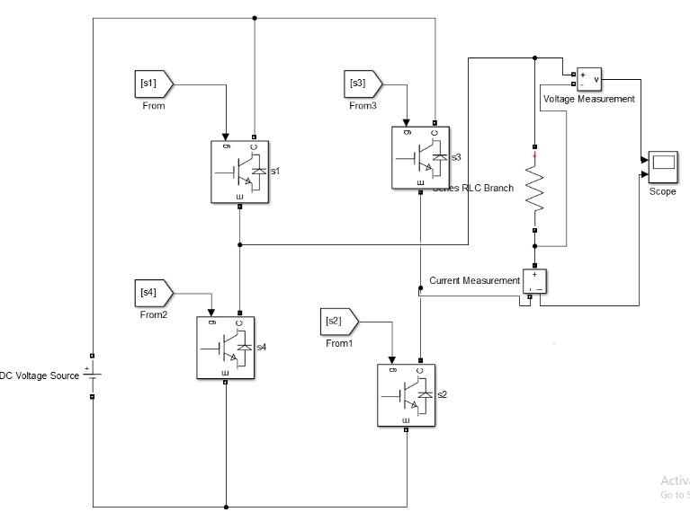
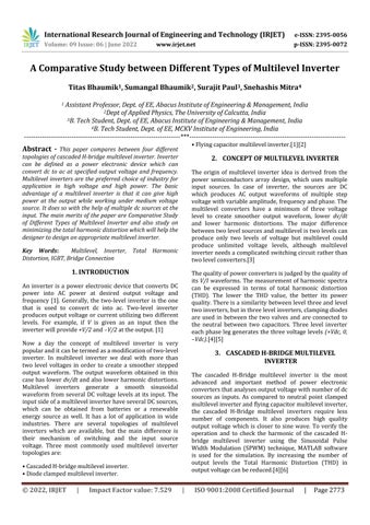
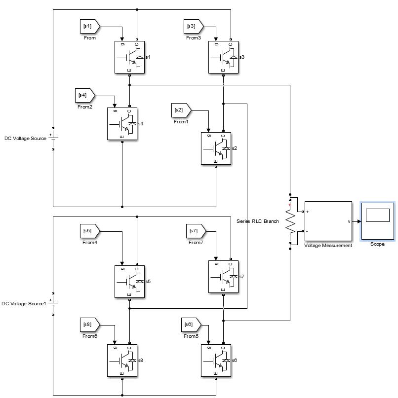
Fig. 1 shows Single phase Three level Cascaded H Bridge inverter consisting of single isolated DC source (V=100) four IGBT switches & load (R=10). The result of output voltage waveform of three levels multilevel inverter is showninfig.2consistsofthreelevels 0, +Vdc, Vdc [7]

Table 1: SwitchingOperationof SinglePhaseThreeLevel CascadedH BridgeInverter
Fig. 1:CircuitDiagramof3rd Level
Different modes of operation of three levels cascaded H Bridgemultilevelinverterareexplainedbelow:
Mode 1
InthismodeofoperationofthreelevelcascadedH Bridge inverter switches s1 & s3 are turned on & no source is connectedtotheload.Zerooutputvoltageacrosstheload isobtained.
Mode 2
InthismodeofoperationofthreelevelcascadedH Bridge inverter, switches s1 & s2 are turned on. Output voltage obtainedacrosstheloadis +Vdc.
Mode 3
Inthismodeofoperationofthreelevelcascaded H Bridge inverter switches s3 & s4 are turned on. Output voltage obtainedacrosstheloadis Vdc
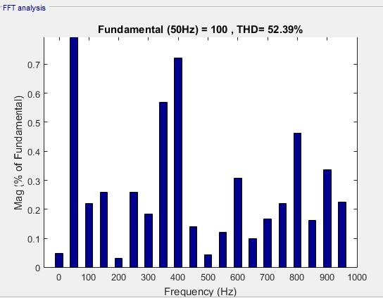
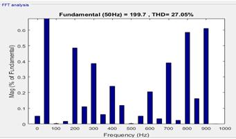
Fig. 2 presents the simulation results obtained for the defined output voltage waveform and Total Harmonic Distortion(THD).
Fig. 2:OutputWaveformof3rd Level Fig. 3:THDof3rd Level
International Research Journal of Engineering and Technology (IRJET) e ISSN: 2395 0056
Volume: 09 Issue: 06 | June 2022 www.irjet.net p ISSN: 2395 0072
Mode5
InthismodeofoperationsinglephasefivelevelsH Bridge cascaded multilevel inverter s3, s4, s7 and s8 are turned on. Theoutputvoltageacrosstheloadobtainedis 2Vdc [8]
Table 2. Switching Operation ofSinglePhase5th Level CascadedH Bridge
Mode S1 S2 S3 S4 S5 S6 S7 S8
1 1 0 1 0 1 0 1 0 2 1 1 0 0 1 0 1 0 3 1 1 0 0 1 1 0 0 4 1 0 1 0 0 0 1 1 5 0 0 1 1 0 0 1 1
Result
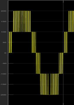
Fig. 4 present the simulation results obtain for the output voltage waveform and also Total Harmonic Distortion (THD).
Fig. 4:CircuitDiagramof5th Level
TheoperationoffivelevelsofcascadedHbridgemultilevel inverter isexplainedbelow:
Mode1
In this mode of operation of single phase five level cascaded H Bridge multilevel inverter, s1, s3, s5 and s7 are turned on without connecting source to the load. The outputvoltageacrosstheloadobtainedis zero
Mode2
In this mode of operation of single phase five level cascaded H Bridge multilevel inverter s1, s2, s5 and s7 are turned on. The output voltage across the load obtained is +Vdc.
Mode3
In this mode of operation single phase five level cascaded H Bridge multilevel inverter s1, s2, s5 and s6 are turned on. Theoutputvoltageacrosstheloadobtainedis +2Vdc
Mode4
InthismodeofoperationsinglephasefivelevelsH Bridge cascaded multilevel inverter s1, s3, s7 and s8 are turned on. Theoutputvoltageacrosstheloadobtainedis Vdc.
Fig. 5: Outputwaveformof5th level
Fig. 6: THD5th Level
International Research Journal of Engineering and Technology (IRJET) e ISSN: 2395 0056
Volume: 09 Issue: 06 | June 2022 www.irjet.net p ISSN: 2395 0072
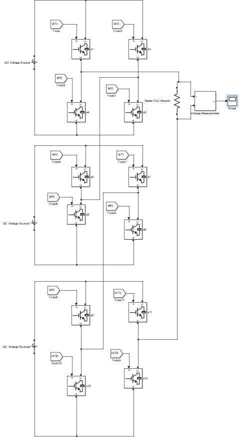
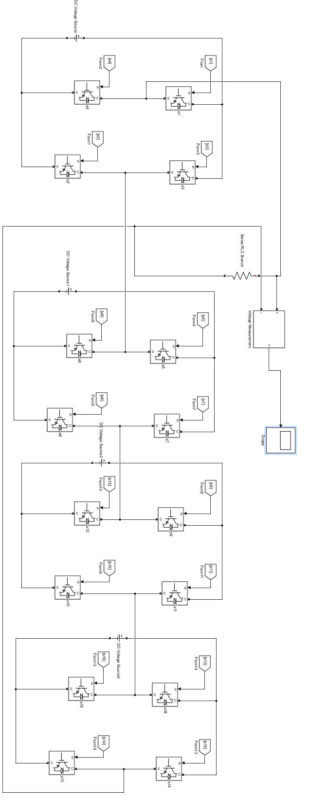
Fig. 5 shows single phase cascaded H bridge multilevel inverter consisting of three H bridges with 12 IGBT switches, three dc source (V=100) and R load (R=10). In this configuration twelve IGBT switches (s1, s2, s3, s4, s5, s6, s7, s8, s9, s10, s11, s12) are used. Three H bridges are connectedinseriestogeneratesevenleveloutputvoltage. The result of output voltage waveform of seven levels multilevel inverter is shown in Fig. 6 which consists of sevenlevels 0, +3Vdc, +2Vdc, +Vdc, 3Vdc, 2Vdc, Vdc [9]
In this mode of operation single phase seven level cascadedH Bridgemultilevelinverter s1, s2, s5, s6, s9 and s10 areturnedon.Theoutputvoltageacrosstheloadobtained is +3Vdc
Mode3
In this mode of operation single phase seven level cascadedH Bridgemultilevelinverter s1, s2, s5, s6, s9 and s11 areturnedon.Theoutputvoltageacrosstheloadobtained is +2Vdc.
In this mode of operation single phase seven levels H Bridge cascaded multilevel inverter s1, s2, s5, s7, s9 and s11 areturnedon.Theoutputvoltageacrosstheloadobtained is 2Vdc.
In this mode of operation single phase seven levels H Bridge cascaded multilevel inverter s3, s4, s7, s8, s11 and s12 areturnedon.Theoutputvoltageacrosstheloadobtained is 3Vdc
Mode6
In this mode of operation single phase seven levels H Bridge cascaded multilevel inverter s3, s4, s7, s8, s9 and s11 areturnedon.Theoutputvoltageacrosstheloadobtained is 2Vdc
In this mode of operation single phase seven levels H Bridge cascaded multilevel inverter s3, s4, s5, s7, s9 and s11 areturnedon.Theoutput voltage acrosstheloadobtained is Vdc [10][11]
Fig. 7: Circuitdiagram of 7th level
The working operation of cascaded H bridge seven levels multilevelisexplainedbelow:
Mode1
In this mode of operation, single phase seven level cascadedH Bridgemultilevelinverter s1, s3, s5, s7, s9 and s11 are turned on without connecting source to the load. The outputvoltageacrosstheloadobtainedis zero.
Mo de S 1 S 2 S 3 S 4 S 5 S 6 S 7 S 8 S 9 S1 0 S1 1 S1 2 1 1 0 1 0 1 0 1 0 1 0 1 0 2 1 1 0 0 1 1 0 0 1 0 1 0 3 1 1 0 0 1 1 0 0 1 0 1 0 4 1 1 0 0 1 0 1 0 1 0 1 0 5 0 0 1 1 0 0 1 1 0 0 1 1 6 0 0 1 1 0 0 1 1 1 0 1 0 7 0 0 1 1 1 0 1 0 1 0 1 0
International Research Journal of Engineering and Technology (IRJET) e ISSN: 2395 0056
Volume: 09 Issue: 06 | June 2022 www.irjet.net p ISSN: 2395 0072
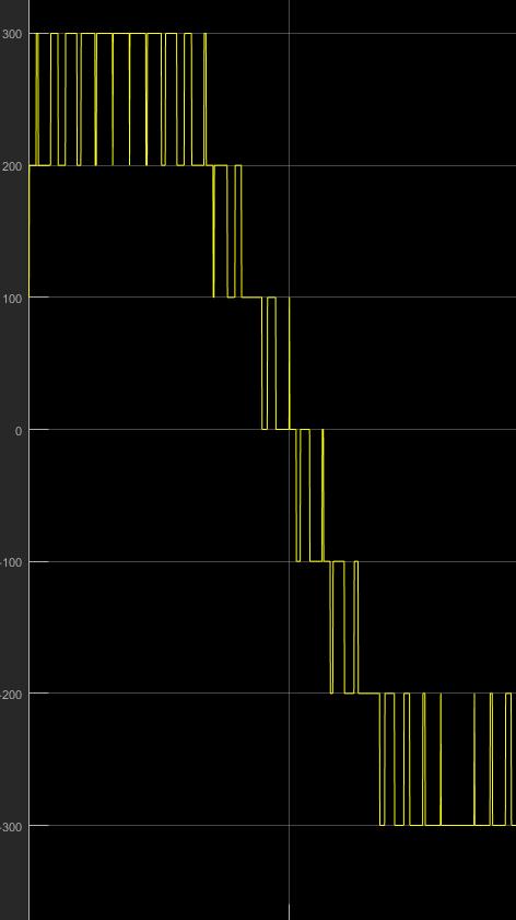
voltage.Theresultofoutputvoltagewaveformof this kind of multilevel inverter is shown in Fig. 8 which consists of nine levels 0, +4Vdc, +3Vdc, +2Vdc, +Vdc, 4Vdc, 3Vdc, 2Vdc, Vdc[12][13]
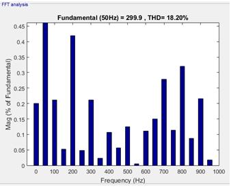
Fig. 8: Outputwaveformof7th level
Fig. 9: THDof7th level
Fig. 7 shows single phase cascaded H bridge multilevel inverter consisting of three H bridges with 16 IGBT switches, three dc sources (V=100) and R load (R=10). In this configuration, sixteen IGBTswitchesare(s1,s2,s3,s4,s5, s6,s7,s8,s9,s10,s11,s12,s13,s14,s15,s16)used.FourH bridges are connected in series to generate nine levels of output
Fig. 10: Circuitdiagram of 9th level Inverter
The working operation of cascaded H bridge nine levels multilevelisexplainedbelow:
Mode1
Inthismodeofoperationsinglephaseninelevelcascaded H Bridgemultilevel inverter s1,s3;s5,s7,s9,s11 ands13,s15
International Research Journal of Engineering and Technology (IRJET) e ISSN: 2395 0056
are turned on without connecting source to the load. The outputvoltageacrosstheloadobtainedis zero.
Mode2
Inthismodeofoperationsinglephaseninelevelcascaded H Bridgemultilevelinverters1,s2,s5,s6,s9,s10 ands13 and s14 are turned on. The output voltage across the load obtainedis +4Vdc
Mode3
Inthismodeofoperationsinglephaseninelevelcascaded H Bridgemultilevel inverter s1,s2,s5,s6, s9,s10 ands13,s15 areturnedon.Theoutputvoltageacrosstheloadobtained is +3Vdc
Mode4
In this mode of operation single phase nine levels H Bridgecascadedmultilevel inverters1,s2,s5,s6,s9,s11 and s13, s15 are turned on. The output voltage across the load obtainedis +2Vdc.
Mode5
In this mode of operation single phase nine levels H Bridge cascaded multilevel inverter s1, s2, s5, s7, s9, s11, s13 and s15 are turned on. The output voltage across the load obtainedis +Vdc
Mode6
In this mode of operation single phase nine levels H Bridgecascadedmultilevelinverters3,s4,s7,s8,s11,s12,s15 and s16 are turned on. The output voltage across the load obtainedis 4Vdc.
Mode7
In this mode of operation single phase nine levels H Bridgecascadedmultilevelinverters3,s4,s7,s8,s11,s12,s13 and s15 are turned on. The output voltage across the load obtainedis 3Vdc
Mode8
In this mode of operation single phase nine levels H
Bridge cascaded multilevel inverter s3, s4, s7, s8, s9, s11, s13 and s15 are turned on. The output voltage across the load obtainedis 2Vdc
Mode9
In this mode of operation single phase nine levels H
Bridge cascaded multilevel inverter s3, s4, s5, s7, s9, s11, s13 and s15 are turned on. The output voltage across the load obtainedis Vdc.[14][15][16]
M o de
S 1 S 2 S 3 S 4 S 5 S 6 S 7 S 8 S 9 S 1 0
S 1 1
S 1 2
S 1 3
S 1 4
S 1 5
S 1 6
1 1 0 1 0 1 0 1 0 1 0 1 0 1 0 1 0
2 1 1 0 0 1 1 0 0 1 1 0 0 1 1 0 0 3 1 1 0 0 1 1 0 0 1 1 0 0 1 0 1 0 4 1 1 0 0 1 1 0 0 1 0 1 0 1 0 1 0
5 1 1 0 0 1 0 1 0 1 0 1 0 1 0 1 0
6 0 0 1 1 0 0 1 1 0 0 1 1 0 0 1 1
7 0 0 1 1 0 0 1 1 0 0 1 1 1 0 1 0 8 0 0 1 1 0 0 1 1 1 0 1 0 1 0 1 0 9 0 0 1 1 1 0 1 0 1 0 1 0 1 0 1 0
Fig. 8 present the simulation results obtain for the output voltage waveform and also Total Harmonic Distortion (THD).
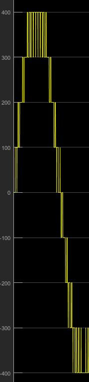
Fig. 11: Outputwaveform9th level
Volume: 09 Issue: 06 | June 2022 www.irjet.net p ISSN: 2395 0072 © 2022, IRJET | Impact Factor value: 7.529 | ISO 9001:2008 Certified Journal | Page2778
International Research Journal of Engineering and Technology (IRJET) e ISSN: 2395 0056
[4] ShahabSajedi,MichaelFarrell,MalabikaBasu,“DCside andACsidecascadedmultilevelinvertertopologies:A comparative study due to variation in design features” , International Journal of Electrical Power & Energy Systems, Volume 113, December 2019, Pages 56 70
[5] A.Khan,M.Ahmad,M.A.Bhatti,M.A.IjazandS.Ullah, "A Comparative Study of Multilevel Inverter Typologies with Reduced Switches," 2019 International Conference on Engineering and Emerging Technologies (ICEET), 2019, pp. 1 5, doi: 10.1109/CEET1.2019.8711851.
[6] Jainy Bhatnagar, Vikramaditya Dave, “A Comparative Study of Different Topologies of Multilevel Inverters” , International Journal of Electrical and Electronics Engineers, Volume No. 9, Issue No 01, January June 2017,Page2050 2056.
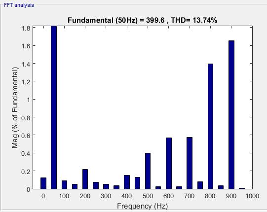
Fig. 12:THDof9th level
In the above, a comparison between different level of multilevel inverter, suchasthethree, five,seven and nine level has been discussed. The comparison of this inverter wasbasedonthecriteriaofoutputvoltage,lowerTHDand to reduce the cost of the inverter as per IEEE 519 standard Thediscussionresultsindepictingtheprosand cons of various types of multilevel inverter, which certainlygivestheideaforfutureworksonthetopic.This discussion will also help the industrial sector in building an efficient inverter technology which might help the industrial sector as well as the households. Also, the advancement in developing efficient inverter might also help in HVDC transmission technology and therefore resultinginefficienttransmission,lowertransmissionloss andbetterpowerquality.
[1] TitasBhaumikandDipuMistry,“UPSwithDualPower Supply for Household Loads’ Energy Conservation,” IRJET,Volume:06Issue:04,Apr2019, pp3846 3849
[2] S. Bhaumik, B. Mondal, J. Bera, “Low Voltage Hardware in LoopTestModelUsingReal TimeDigital Simulator for Single Phase Converter”, vol 537. Springer, Singapore. https://doi.org/10.1007/978 981 13 3450 4_10
[3] Mohammad Tayyab,Adil Sarwar,Md Reyaz Hussan,Shadab Murshid,Mohd Tariq,Basem Alamri,“A novel voltage boosting switched‐capacitor 19‐level inverter with reduced component count”, International Journal of Circuit Theory and Applications, 10.1002/cta.3235,50, 6, (2128 2149), (2022).R.Nicole
[7] AddagatlaNagarajuandAkkelaKrishnaveni“Modified Multilevel Inverter Topology with Minimum Number of Switches”, International Journal of Science Technology & Engineering, volume 3 issue 09 March 2017
[8] Niralkumar Rakholiya et al. “Multilevel Inverter Topology” International Journal for Innovative Research in Science & Technology volume 3 issue 11 April2017.
[9] Anjali Krishna R. and Dr. L Padma Suresh “A Brief ReviewOnMultilevelInverterTopologies”Conference on Circuit, Power and Computing Technologies [ICCPCT]2016.
[10] Y. Sato, M. Kawasaki, and T. Ito “A Diode Clamped Multilevel Inverter with Voltage Boost Function”, 8th InternationalConferenceonPowerElectronics ECCE AsiaMay30 June3,2011.
[11] Kamaldeep Boora and Jagdish Kumar “General topology for asymmetrical multilevel inverter with reduced number of switches”, IET Power Electronics 2017
[12] Aditay Vardhan Singh, Ravi Shankar Singh, “A ComparativeStudy ofMultilevel InverterTopologies” , IRJET, Volume: 05 Issue: 03 | Mar 2018, pp 1009 1014.
[13] Shraddha S. Lohakare, Dr. Pravin M. Sonawane, “Comparative Study on Five and Nine Level MLI for Percentage THD Reduction”, IJRECE VOL. 7 Issue 1 (January March2019)ISSN:2393 9028|ISSN:2348 2281(Online)
Volume: 09 Issue: 06 | June 2022 www.irjet.net p ISSN: 2395 0072 © 2022, IRJET | Impact Factor value: 7.529 | ISO 9001:2008 Certified Journal | Page2779
International Research Journal of Engineering and Technology (IRJET) e ISSN: 2395 0056
Volume: 09 Issue: 06 | June 2022 www.irjet.net p ISSN: 2395 0072
[14] M.Ahmad,T.Muhammad,R.UzamanandO.Khan,"A Novel Asymmetric Three Phase Multilevel Inverter with Reduced Switches", Sukkur IBA Journal of EmergingTechnologies,2018
[15] Pallavi Appaso Arbune, Dr. Asha Gaikwad, “Comparative Study of Three level and Five level Inverter” , International Journal ofAdvancedResearch in Electrical, Electronics and Instrumentation Engineering, Vol. 5, Issue 2, February 2016, pp 681 686.
Titas Bhaumik, with academic experience of over 6 years, is currently working as Assistant Professor, Dept of EE, AIEM (JIS Group), resides in Mogra, West Bengal,India.


SumangalBhaumikcompletedhis M.Tech in Electrical Engineering from University of Calcutta. Now he is attached with Techno and JISgroupasafacultyofElectrical Engineering Department, currently resides at Kalyani, India.
Surajit Paul, currently at third year of B. Tech in Electrical Engineering, AIEM, resides in Kolkata,India.
Snehashis Mitra, currently at third year of B Tech in Electrical Engineering, MCKV Institute of Engineering, resides at Howrah, India