International Research Journal of Engineering and Technology (IRJET) e ISSN: 2395 0056

Volume: 09 Issue: 06 | Jun 2022 www.irjet.net p ISSN: 2395 0072
International Research Journal of Engineering and Technology (IRJET) e ISSN: 2395 0056
Volume: 09 Issue: 06 | Jun 2022 www.irjet.net p ISSN: 2395 0072
1,2,3,4 Student, Department of Mechanical Engineering, 5AssistantsProfessor, Department of Mechanical Engineering, Mangalore Institute of Technology & Engineering-Badaga Mijar, Moodabidri 6CEO, Decibels Lab Pvt Ltd, Bangalore
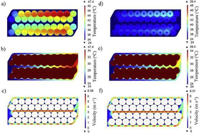
Abstract: TheBTMSisacrucialcomponentofanelectric vehicle (4) thathasadirectimpactonitsperformance.This researchprovidesaCFDmodelthatimprovestheaccuracy of data received from temperature analysis inside battery packs.Effectivemodeldesignanddevelopmentofabattery pack increases the life of the battery cells and the electric vehicle'senergyefficiencyinexcellentspecifiedroadtraffic circumstances. The thermal in the battery pack research methodologyisbasedonanefficientco simulationconcept that includes steady state CFD simulations (4) and a researched analysis model for the thermal behavior of a lithium ion(Li ion)cylindricalbatteryandisappliedinthe battery pack's forced air cooling thermal management systemandliquidcoolingsystem.Whencomparingthetwo data, we may conclude that liquid coolant systems have higherheatconductivityandheatcapacitythanair,i.e.,the capacitytostoreheatasenergyinitsbonds (6). Asaresult, batteryperformanceissignificantlyimproved,andSOCmay bemaintainedforlongerperiodsoftime.
The transportation sector primarily runs means of transportationpoweredwithinternalcombustionengines usingfuelslikediesel,petroletc,itaccountsfor27percentof theworldeconomy'stotalenergyusage.So,thegreenhouse gas will affect the environment the gasses like Carbon monoxide,nitrogen oxides,hydrocarbons,volatile organic compounds, and other pollutants are released into the environmentwheninternalcombustionenginesareused.As aresult,developingandusingelectriccarsmightbeaviable optionforloweringgreenhousegasemissionsandpollution that depletes the ozone layer. (1). Many technologies for electricvehiclesarenowbeingdeveloped,withthegoalof increasing electric cars' and electric powertrains' total efficiency.Electricvehicles, therefore,requiresinorder to provide an alternative solution to internal combustion enginevehicles,ahighdevelopedandcomplicatedstructural systemforcontroller,alargeamountofpowerdensityofthe energy source, the longer self lifeof lithium ion batteries, andgreaterefficiencyforpowerelectronicequipmentwith futuristicfeaturesarerequired.Togivealongdrivingrange andahighbattery%efficiency,lithium ionbatterieswitha highdensityandhighenergyarethemostpreferredpower sources. Li ion batteries, on the other hand, emit a large amount heat leads to quick state of charge at high power
consumption,andthetemperatureincrease,andconsistency willimpairtheirenergystoragecapacityandlifetime (1).
Thenecessityofkeepingandoptimizingthebatteriestoan optimal temperature range that is adequate has been demonstrated through studies and research. According to research, the working temperature range for lithium ion batteriesis15to50degreesCelsius (2),withatemperature rise of one degree reducing the battery's lifetime by two months. Also, to support battery balance and consistent charging during the cycle, the maximum temperature differentialinabatterypackshouldbekeptbelow5degrees Celsius.(1),sothatthebattery'slifecyclemaybeextended byacomparablemarginandthebattery'sperformancecan beexpectedtobeuniform.
Accordingtorecentstudies,atemperatureriseinLi ioncells inducedbyalargerstateofSOCcanreducebatterylifeby66 percent to 97 percent. Based on the above statement, a correctdesign,modification,andconstructionofa battery thermalmanagementsystem(BTMS)isessentialforelectric vehicles.Withrighttechnique,wecanmaintainidealthermal operating conditions. According to recent studies, a temperatureriseinLithiumcellsinducedbyahigherrateof SOCcanreducebatterylifeby66percentto97percent.A correctdesign,modification,andconstructionofathermal managementsystemforanelectricvehicle'sbattery(BTMS) is necessary based on the above assertion; with the right approach, we can maintain perfect thermal operating conditions, with right technique, we can maintain ideal thermaloperatingconditions.Asaresult,thebattery'sBTMS is used to optimize a safe temperature range for the batteries. Various research on BTMS, including cooling techniques and battery thermal modelling design models, havebeenconducted.Thermalcoolingsystemsincludeair cooling,liquidcooling,heatpipecooling,andphasechange material(PCB)cooling.Liquidcoolinghasahigherthermal conductivity coefficient and performs better in general. However,theextrapayloads,suchasliquidcoolant,casing, and sealing devices to avoid liquid leakage, as well as the highcostsoftheliquidcoolantcirculationsystem,reduceits effectiveness.
Air coolingisthemostextensivelyutilizedcoolingsystems inBTMSbecauseitisinexpensiveandeasytomaintain,and it’sfrequentlyusedinelectricandhybridvehicles.Theuseof
International Research Journal of Engineering and Technology (IRJET) e ISSN: 2395 0056
aforcedair coolingsystemiscommon.Whichflowscooled air into the battery cells. Reduce the cycle rate of the cell, lower the temperature, and this will function within the intendedrange.However,agreatercyclerateofthebattery causesasignificantincrease intemperature,necessitating thecirculationofaconsiderablevolumeofairtowardsthe battery module in order to maintain or lower the rising temperature(1).
Methodology:
Step1:Definingtheparameter
Step2:3Dmodelling
Step3:CFDAnalysis
Step4: Simulation
Step5:ResultantGraphComparison
Methodology of Study:
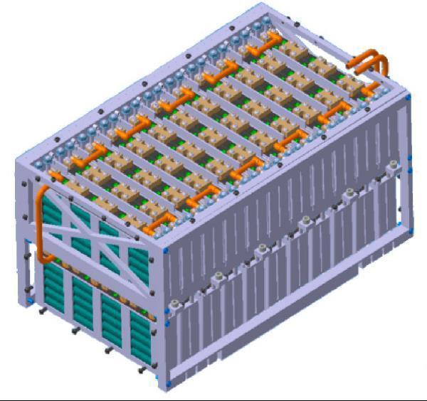
The procedures for determining the temperatures in the batterycell'score,asillustratedinFig.1,areasfollows:
1.Theamountofelectriccurrentdrawnfromthebatteries during EV operation and the amount of temperature rise causedbythebatteries,ascalculatedusingsimulation.
2.ComputationalFluidDynamicssimulationstomanageand maintain the coefficient of heat transfer values on the batterieswithinaspecifiedrangeatvarioustemperatures andairflowrates(2).
3. Complete the heat transfer maps gathered, create a mathematical model and assess the thermal performance (2).
The amount of heat produced by the Li Ion cells and the batterypackisrelatedtothebatterydemand,andhencethe vehicle'soperatingmode.Thermalcriteriaimposedonthe batterypackarespecifiedbycompleting22kilometersona racetrackwithoutexceedingthe50°Crestriction.Thefigures are based on the velocity profile of a Formula Student EV duringafastlapofGermany'sHockenheimringcircuit.The electriccurrentrequiredtobeprovidedbythebatterycells ateachpointoftheeventandtheheatloadthatthebattery's coolingsystemwillhavetobearmaybecalculatedusingthe velocityprofileoftheaccelerationsandtheparameters of theexaminedpropulsionsystem.Thefollowinginformation is available about the building of the examined electric prototypepowertrain.
Batterypack:4
Batterysubsystem
Coldplatesubsystem
Coolingplatesubsystem
Heating coolingunitsubsystem
Refrigerantsubsystem
Radiatorsubsystem
Pumpcontroller
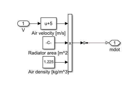
Airstream
Environment
FTP 75Drivecyclecoolant
Tobegin,theelectriccurrentdrawnfromthebatterycells
must be calculated based on the motors' power requirementsandthebattery'slevelofcharge.Thevehicle's longitudinal resistance forces to achieve the necessary to calculate the velocity profile. The resistance force, aerodynamicdrag force,andacceleration resistance force areestimatedbecauseofthis.Therollingresistanceforce, aerodynamic drag force, and acceleration resistance force are estimated because of this. Their sum produces the traction force necessary at the wheel, which is used to calculatethetorqueatthewheelandmotortorquerequired for the desired performance The mechanical power producedbythemotorsmaybecomputedatanytimeusing themotorspeedprovidedbythevelocityprofile.Inaddition tothepowernecessaryforacceleration,thepossibilityfor energyrecoveryviaregenerativebrakingisconsidered.The neededelectricpowerforeachmotoriscomputedusingthe efficiencymap,whichisthenusedtocalculatetheamountof electricity to be pulled from the battery based on state changes(2).
Powerprofilesarerepeated23timesthroughoutasinglelap to create a power profile to reach 22 kilometres in 1960 seconds, while the value of the electric vehicle remains constant(1).
Volume: 09 Issue: 06 | Jun 2022 www.irjet.net p ISSN: 2395 0072 © 2022, IRJET | Impact Factor value: 7.529 | ISO 9001:2008 Certified Journal | Page2743
International Research Journal of Engineering and Technology (IRJET) e ISSN: 2395 0056
The current to be drawn from the battery is computed separatelyfromthevoltageatthebattery'soutputbasedon itsstateofcharge(SOC)(1).
State of Charge (SOC):Stateofchargereferswithrelationto theamountchargedinabattery.TheestimationsofSOCcan addtotheperformanceofBMSanditsdependability.Battery charge and discharge cycles involve release of complex substances like arsine in case of lead acid batteries, CadmiumincaseofNickel Cadmiumbatteries,Fluoridegas in case of Lithium ion batteries, and their estimation is difficulttomake.ItisthereforedifficulttoappraisetheSOC preciselyunderdifferentoperationalconditions.Therearea few sorts of LIBs in the market, for example, those containingLiFeO4,lithiumpolymersandLiCoO2thatinvolve high emission of power from the battery and possess complex topology of battery cells where SOC calculations requiretime.
Temperature monitoring: Thermistorsaretypicallyused to cover the battery's temperature. The temperature informationfromthethermistorisfrequentlyreadoutofan ADC.Temperaturedetectorsscreeneverycellofanyenergy storagesystem(ESS)likepowerbanksoranassemblingof cellsincaseofsmallbatteriesusedinadaptableoperations. Sincethechemicalcompositionusedtodevelopabatteryis unchangeable,alsoabatterywithrepeatedcurrentspikecan resultinthebatterytouchoff.Temperatureestimationsare not only limited to optimize the temperature but also monitorthesaferangeofchargeortodischarge.Ininorder to keep the cells' temperatures within the desired range, coolantiscirculatedaroundthesurfaceofthebatterypacks.
Thermal management: Thermal management involves monitoring and regulating battery temperature to ensure thatthebatteryisnotharmedbyhighorlowtemperature. Unlike SOC and SOH that depend on more than one parameter for their estimation, temperature estimation solely depends on the dimension of individual cell temperature.Thermalmanagementisdonebycontrollinga fanoranelectricwarmer,asneeded,whichhelpstokeepthe temperatureofthebatteryunderidealconditions.Athermal managementequipmentestimatesthebatterytemperature bythermaldetectorsandperformscoolingorwarmingtasks and sends an extreme flag to the Control Unit about its variation.
SoC = SoC0 − 1 CAh Z t t0 I(t)dt (1) where SoC is the original state of charge (2).
CAh denotes battery capacity, while I denote uprooted current.
Thevoltageofthebatteriesiscalculatedusingthedatatable andthetemperaturecurveatparticulartemperaturei.e.45 C,basedontheirstateofcharge.Usingtheobtainedcurrent value,thetemperatureriseofeachbatterycelliscalculated asfollows:
=I2·Rint−IT·dEOVdT(2)
When intrinsic resistance exists Rint is calculated from a chart based on the SOC (Rint = f (C rate, SoC)) and, using Drake'sexperimentalobservations,Timpliestemperature and dEOV/dT represents the entropic coefficient. The battery'sC rateandSoC.Thus,Figure4cdepictstheaverage rangeoftheheatcreatedbythebatterycellsduringthetest onendurance(2).
sequals1W/cellCFDSimulations2.3Onthesurfaceofthe battery cells, the heat transfer coefficient is determined usingthefluentsolver.TheprimarypurposeofutilizingCFD simulations is to estimate SOC values for various occurrences of produced heat and air movement. These findings are then used to create heat transfer maps that discriminatethermalbehaviorundervarioussettings.The justificationforutilizingthisapproach,whichinvolvesdoing brief simulations with a 1D model that incorporates the featuresgeneratedfrom3DCFDsteady statesimulations,is the significant decrease in computing work required. The justificationforutilizingthisapproach,whichinvolvesdoing brief simulations using a 1D model that incorporates the featuresgeneratedfrom3DCFDsimulationsinsteadystate, isthesignificantdecreaseincomputingworkrequired.The goalofthefirstphaseistodevelopareferenceCFDmodel thatcanbeutilizedfortheotherinvestigatedscenarios.The meshsystemiscreatedattheinterfaces betweenthefluid layer and the cell borders, as well as between the fluid layers. The following equation is used to compute the thicknessofthefirstinflationlayerfory+=1(2).
∆y=Dh·y+·√74·Re−13/14D
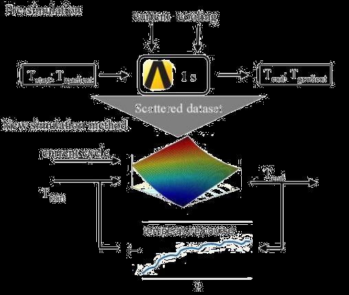
ThemodelisdevelopedusingAnsysworkbench.Thevalue ofthecelliscalculatedanddefinedintheANSYSworkbench thepropertiesareaddedaccordingtothecell.HeretheLi ioncellisusedforthestudy
Volume: 09 Issue: 06 | Jun 2022 www.irjet.net p ISSN: 2395 0072 © 2022, IRJET | Impact Factor value: 7.529 | ISO 9001:2008 Certified Journal | Page2744
International Research Journal of Engineering and Technology (IRJET) e ISSN: 2395 0056
Volume: 09 Issue: 06 | Jun 2022 www.irjet.net p ISSN: 2395 0072
Whenthecarisinaccelerationmode,thebatteryisrapidly depletedatbothends,onthepositiveandnegativesidesof theelectrode.Asaresult,thetemperaturewithinthebattery rises,andthebatterylifeisaffectedbyhowhotthebattery is. We all know that the lithium ion battery's optimum temperatureisatornear35degreesCelsius.
Withinthistemperaturerange,thebatteryperformanceis excellent, and we may anticipate a long battery life. As a result, battery cooling is required to maintain this temperature.
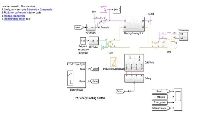
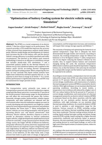
The primary goal of a thermal management, battery pack willbedeliveredviathesystem.Withanacceptablemean andconstantAccordingtothebatteryprovider,temperature distribution (or even minor variations) across the battery modules of the battery cell, it must also be accurate and accessible for routine maintenance. Setting up a proper thermalmanagementsystemwillhelptoproperlydissipate heatfromthebatterypack,reducingexcessivetemperature increases,andimprovingcharginganddischargingstability and protection. LIBs have two forms of thermal management: cooling and heating. The heat management system for the battery module must be small, light, economical,easilypacked,andsuitablewiththelocationof the car manufacturer in the vehicle. The BTMS may be dissolved into a few primary parts/sections using a hierarchicalmodel'sdecompositiontechnique,asillustrated in Fig. 3, including the battery cell, air intake system, and battery module. Every sub system is further divided into secondary sub systems that are categorized into different domains, such as fluid dynamics, thermodynamics, and structureinthecaseofthebatterymodule(3).
Thesimulationhasbeencompleted.Thetemperaturewithin the battery pack is determined by the fig 6 above. When water + Ethelyn glycol is employed as the solvent, liquid cooling is used to progressively lower the temperature within the battery pack. As a result, it's vital to keep the batterypackattherighttemperature.
TheMATLABfindingshavebeencompleted.
ThisistheFTP 75cyclewhichisalsocalledthefast charging cycleortheEuropeanstandardcycle.
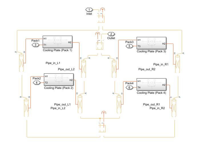
Fig6:Coldplatessubsystem
International Research Journal of Engineering and Technology (IRJET) e ISSN: 2395 0056
Volume: 09 Issue: 06 | Jun 2022 www.irjet.net p ISSN: 2395 0072
Coldplate’sfunctionisthatthecoolantpassesthroughinlet passesthroughallthehotpipesobservethereheatandthen it goes out through the outlet and this cycles repeats simultaneously
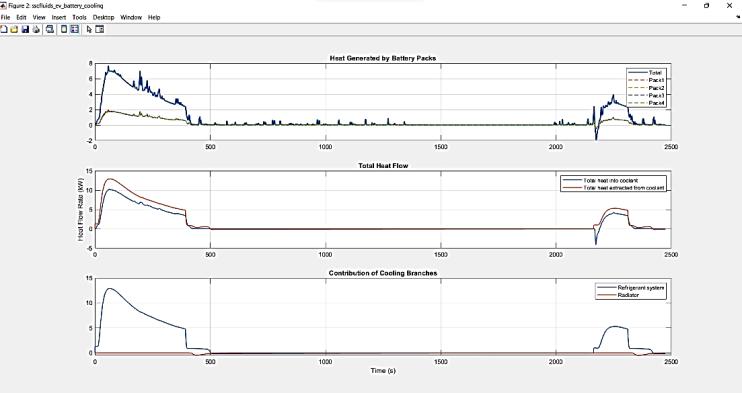
Fig10:HeatflowGraph
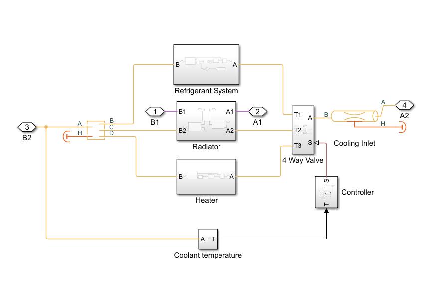
These heating cooling unit is used in some of weather conditionslikerainyorincoldconditionsthebatteryneeds some minimum heat for its best performance at that time thisheatingcoolingunitisused.
The Coolant adopted here is propylene glycol + water mixtureforbestperformanceinthebattery
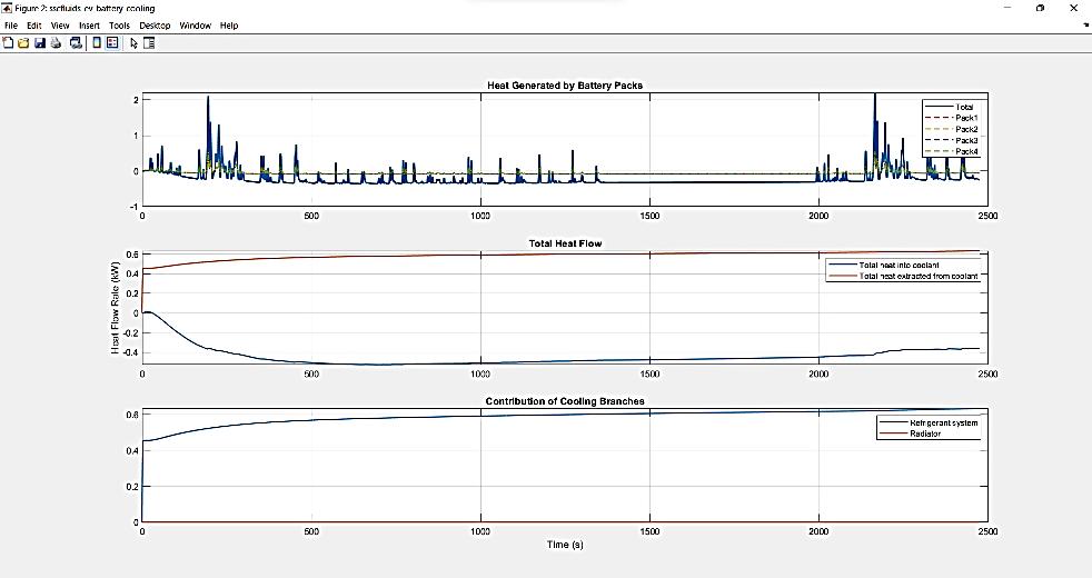
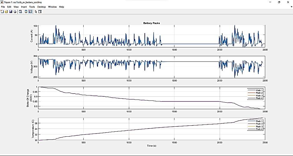
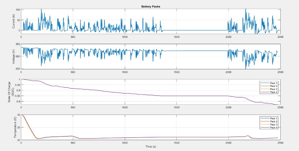
Fig8:AirStream
Fig12:Batterypacktemperatures
Fig9:Batterypacktemperaturegraph
© 2022, IRJET | Impact Factor value: 7.529 | ISO 9001:2008 Certified Journal | Page2746
International Research Journal of Engineering and Technology (IRJET) e ISSN: 2395 0056
Volume: 09 Issue: 06 | Jun 2022 www.irjet.net p ISSN: 2395 0072
1. Alhindawi, R.; Nahleh, Y.A.; Kumar, A.; Shiwakoti, N. Projection of Greenhouse Gas Emissions for the Road TransportSectorBasedonMultivariateRegressionandthe DoubleExponentialSmoothingModel.Sustainability2020, 12,9152.[CrossRef]
2. Transport&Environment.CO2EmissionsfromCars:The Facts;EuropeanFederationforTransportandEnvironment AISBL:Brussels,Belgium,2018.
3. Giakoumis, E.G. Diesel and Spark Ignition Engines Emissions and After Treatment Control: Research and Advancements.Energies2017,10,1882.
Fig13:HeatFlowgraph
The outcome of the MATLAB result is compared with analytical solution of the previous work. Here we can see thatwhenweusecoolantSAE 30asthecoolantthebattery performancegraphwillincreaseinthenormalacceleration sothere,wecanseetemperatureincreaseupto35°C. We know that the optimal temperature of the Li ion cell is around 35°C this when the LI ion cell is maintained in optimaltemperature.Wereasintheevvehicletherewillbe increase in acceleration, so the input required to the EV vehicle depends on the road conditions.so temperature in thebatteryincreaseswhenrequiredinputismoresointhis model,wehaveusepropyleneglycol+watermixtureasthe coolant. We can see that the battery performance graph decreases gradually so here we can see that the battery coolantbatteryworksproperly,andwehaveoptimizedthe batterytemperature.
4. Tran, T.H.; Harmand, S.; Sahut, B. Experimental investigationonheatpipecoolingforhybridelectricvehicle and electric vehicle lithium ion battery. J. Power Sources 2014,265,262 272
5. Lee,S.;Cho,W.;Do,V.;Choi,W.EffectsofPulseCurrent Charging on the Aging Performance of Commercial CylindricalLithium IonBatteries.Appl.Sci.2021,11,4918.
6. Chen,M.;Zhang,S.;Wang,G.;Weng,J.;Ouyang,D.;Wu,X.; Zhao, L.; Wang, J. Experimental Analysis on the Thermal Management of Lithium Ion Batteries Based on Phase ChangeMaterials.Appl.Sci.2020,10,7354.
7. Zhao,R.;Gu,J.;Liu,J.Anexperimentalstudyofheatpipe thermalmanagementsystemwithwetcoolingmethodfor lithium ion batteries. J. Power Sources 2015, 273, 1089 1097.
8. Pesaran,A.A.Batterythermalmodelsforhybridvehicle simulations.J.PowerSources2002,110,3377 3382.