International Research Journal of Engineering and Technology (IRJET) e ISSN: 2395 0056

Volume: 09 Issue: 06 | June 2022 www.irjet.net p ISSN: 2395 0072
International Research Journal of Engineering and Technology (IRJET) e ISSN: 2395 0056
Volume: 09 Issue: 06 | June 2022 www.irjet.net p ISSN: 2395 0072
,
Anil Kumar Gujjal61,2,3,4 Student, Department of Mechanical Engineering, 5AssistantsProfessor, Department of Mechanical Engineering, Mangalore Institute of Technology & Engineering Badaga Mijar, Moodabidri 6Assistant Manager, JSW Steels Ltd, Bellary ***
Abstract -The chassis, one of the most important sections of a vehicle, is the structural backbone of commercial vehicles. According to a groundbreaking study, chassis are subjected to high loads, which can lead to undesirable behavior such as cracks or severe failure. Furthermore, although not particularly explored, The impact of specific materials on chassis behaviour when subjected to stress has piqued researchers' interest. Based on the findings of these studies, it is possible to conclude that more chassis research is needed to generate data for future consideration in the evaluation & development of vehicle chassis designs.The chassis' main purpose is to support the components and cargo that are attached to it..When building a big truck chassis, many factors were taken into account, including material selection, strength, stiffness, and weight. This study focuses on the static and dynamic properties of a utility vehicle prototype ladder frame chassis. The chassis was created using the modeling software Autodesk Fusion 360, and the analysis was also carried out using Autodesk Fusion 360. To complete the chassis meshing, the auto meshing feature will be used.
Key Words: Ladder frame chassis, Step up Chassis, Fusion 360, Stress analysis, Displacement testing, structural analysis.
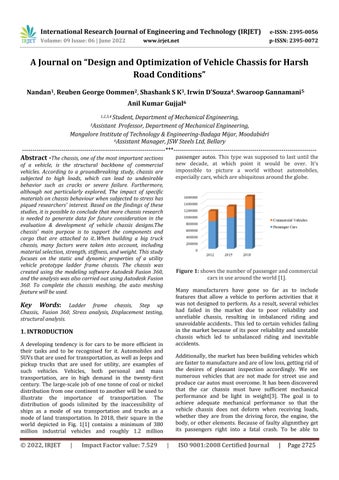
A developing tendency is for cars to be more efficient in their tasks and to be recognised for it. Automobiles and SUVsthatareusedfortransportation,aswellasJeepsand pickup trucks that are used for utility, are examples of such vehicles. Vehicles, both personal and mass transportation, are in high demand in the twenty first century. The large scale job of one tonne of coal or nickel distributionfromonecontinenttoanotherwillbeusedto illustrate the importance of transportation. The distribution of goods islimited by the inaccessibility of ships as a mode of sea transportation and trucks as a mode of land transportation. In 2018, their square in the world depicted in Fig. 1[1] contains a minimum of 380 million industrial vehicles and roughly 1.2 million
passenger autos. This type was supposed to last until the new decade, at which point it would be over. It's impossible to picture a world without automobiles, especiallycars,whichareubiquitousaroundtheglobe.
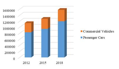
Figure 1: showsthenumberofpassengerandcommercial carsinusearoundtheworld[1].
Many manufacturers have gone so far as to include features that allow a vehicle to perform activities that it was not designed to perform. As a result, several vehicles had failed in the market due to poor reliability and unreliable chassis, resulting in imbalanced riding and unavoidable accidents.. This led to certain vehicles failing in the market because of its poor reliability and unstable chassis which led to unbalanced riding and inevitable accidents.
Additionally,themarkethas been building vehicles which arefastertomanufactureandareoflowloss,gettingridof the desires of pleasant inspection accordingly. We see numerous vehicles that are not made for street use and produce car autos must overcome. It has been discovered that the car chassis must have sufficient mechanical performance and be light in weight[3]. The goal is to achieve adequate mechanical performance so that the vehicle chassis does not deform when receiving loads, whether they are from the driving force, the engine, the body, or other elements. Because of faulty alignmthey get its passengers right into a fatal crash. To be able to
International Research Journal of Engineering and Technology (IRJET) e ISSN: 2395 0056
Volume: 09 Issue: 06 | June 2022 www.irjet.net p ISSN: 2395 0072
challenge such narration and to build an excellent chassis keeping in mind the price and usability, we have constructed a chassis that is used for load carrying conditionsandisspeciallyfortransportationofgoodsand manners. To accomplish that, we've carried out various kindsandmakesuseofchassisandunderlinedthevarious makesuseofeachandnarroweditrightdowntoonekind. Then there has been the design component, which appeared to be the most critical part of growing a chassis and so, the hunt for current chassis gave us clean information on how and why chassis became created and built that manner. a lot of such chassis had been of the Mahindra Scorpio, Balero, Tata Yodha Pickup, and many others.
A big diameter thin wall tube is defined as a perfect chassis.ThetermchassiscomesfromtheFrenchlanguage, and it was originally used to refer to the vehicle's frame and basic structure. The two basic aims of an automobile chassiscanbedefinedasfollows:
Tosupportthecomponents'weight.
While moving, the suspension components must be heldtogetherrigidly.[2]
Nicolaus Joseph Cugnot developed the first widely known carin1769,andCharlesandFrankDuryeadiscoveredthe first vehicle chassis. A vehicle, such asa car, must have at least three main components: a chassis, a body, and an engine. The chassis is the body that guides the uses of a vehicle, as well as supporting other elements such as the body, engine, passenger, and other automobile components.The body of a vehicle is the outermost section, and the engine is the driving part, but the chassis is the body that guides the uses of a vehicle, as well as supporting other parts such as the body, engine, passenger,andotherautomobilecomponents.[1]
Until date, there have been four different types of lattice utilized in auto diligence, including Monocoque, Tubular lattice, Lattice Backbone, and Graduation Frame. Monocoque refers to a chassis in which the body and chassisshapesaremergedtogether[2].Ladderframesare a type of chassis that get their name from their shape, which resembles a ladder. This chassis is the oldest of all chassis types, and it's used in big motors and trucks. It's having a hard time keeping up with the increased demands for higher overall performance and lighter weight in order to meet fuel economy criteria. Shaped blocks are commonly utilized to construct this chassis, which can then be linked together via rivet or weld connections[4]. In another research of vehicle design, thereareobstaclesforchassisthatthosewhowanttoent geometryandvariousmechanicalissues,iftheautomobile chassis deforms or bends, it will result in bad handling / uneven handling. Excessive torque can be applied to
driveline components, and body part spacing is inconsistent.Thetheorybehindthelighterchassisconcept isthatifthevehicle'sweightisreducedwhilemaintaining the same strength, the vehicle will naturally save more gasoline. The theory behind the lighter chassis concept is that if the vehicle's weight is reduced while maintaining the same strength, the vehicle will naturally save more gasoline.
The chassis determined for the study is that of a Ladder chassis,astheyaremostnormallyused,sincethefactthat it is the chassis selected for most of the heavy loading situationsandheavytransportation.Beingtheoldestform of chassis, it received its name from the fact that it is formed as a ladder. The most satisfactory part of the chassis is that it's less complicated to fabricate and use. From the start of the car, era touching on the uses and designingofchassisbecame notatallcomplexanddue to itsmulti fuction,becameusedinbignumbers.
The Advantages is that being less difficult to assemble as components can be without problems put in, the construction method makes it quite tough, easier to fix as elements aren't permanently attached.The worst part is that the chassis has a weak torsional stiffness, making it difficult to corner. Because of its weight, it is not suitable forsportsvehiclesorhatchbacks.
When it comes to selecting materials for vehicle chassis assembly,Itis necessaryto consider factorssuchassafety and weight. The value of resources is enormous.. As a result, recyclable materials should be used. While absorbing impact energy,thematerial will have toensure passenger safety also. The overall weight of the chassis is lowered by using lightweight materials in the chassis, which also helps to reduce fuel consumption. Optimizing andbalancingsolutionswillallowforsuccessfuldesign. In the near future, societal and legal demands, such as the desire to maintain the natural environment and use resourceswisely,willalmostcertainlybeamajordriverof change[10].
International Research Journal of Engineering and Technology (IRJET) e ISSN: 2395 0056
Volume: 09 Issue: 06 | June 2022 www.irjet.net p ISSN: 2395 0072
The following are the most significant criteria that a materialmustmeetforvehiclemanufacturers:
Lightweight: Given the great priority placed on greenhouse gas reductions, emissions reductions, and improved fuel efficiency, his requirement for an automotiveindustry.
Economic effectiveness: They are doing so with the understanding that one of the most important consumer driven criteria in the automotive industry is cost, which decides whether a novel material has a chance to be chosenforacarcomponent.
Safety:The criteria take into account the ability to absorb impacting energy through regulated failure modes and systems,aswellasthepassengers'abilitytosurvive.
Recyclability of their products and Life cycle: Its main issues in the automotive industry are resource conservation and recycling options, which include R&D strategiesfocusedonrecyclingprocessesandthecreation of more easily recyclable materials, as well as their inclusionintovehiclesandtheirconstituentcomponents.
Aluminum, steel, carbon fibers, composites, and other materials are commonly used. Automobile manufacturers use steel and its alloys as their main choice for chassis construction.Steelisthemostpopularmaterialbecauseof itsresistance,temperatureresistance,anddurability.Asa result of research and development, steel materials have improvedinstrength,stiffness,andlightness.Steelandits alloys areused in a widerange of automobiles because of their material properties. Steel, especially 'A36' steel, is a ductilematerialthatiscommonlyusedinchassisbuilding. Connecting two A36 steel components can be done via welding and bolting. The material characteristics of A36 steelcanbeobserved.
Property Values of steel A36
Density 7.85g/cm3
ModulusofElasticity 200GPa
Poisson’sRatio 0.26
Yield.strength 250MPa
UltimateTensilestrength 500MPa
ThermalConductivity 0.045W/(mmC)
Thermal.ExpansionCoefficient 1.17E 05/C
Table 2: PropertiesofSteelA36
TheCentralMotorVehiclesRulesapplytoall automobiles in India (CMVR). According to the CMVR's 93rd rule in chapter 5, construction equipment and maintenance of motor vehicles, "The entire width of the vehicle shall not exceed 2.6 metres when measured between the perpendicular planes of the vehicle axis at right angles," says the manufacturer. And "The vehicle's entire length shall not exceed 6.5 metres, and there should be no more than two axles. "This only applies to vehicles that do not fallunderthecategoryoftransportation."[19]
The ladder chassis is utilized for the MUV vehicle. The design's layout resembles a ladder, as the name implies. Thechassis' designspacewill bea rectangle,according to the dimensions. The two longitudinal rails appear on the rectangle'slongestsideinthedesignspace.Theserailsare joined by cross members, which are a type of support member.
Channel sections, tube sections, and box sections are the most common longitudinal rail sections. It's worth noting that the box portion resists torsion and bending better than the channel and tubular sections. As a result, the longitudinalrailsaremadeofaboxsection.Therearetwo types of portions in the box section. One is square hollow portion,whiletheotherisrectanglehollowsection.
Becausetherectangularhollowsectionhasahighmoment ofinertia,ithasahighresistancetotransverseandlateral loading. As a result, the beam with higher depth is more powerful. As a result, for longitudinal rails, a rectangular hollowsectionischosen.Cross membersjoinlongitudinal rails together. The engine, transmission system, suspension system, and axles are all supported by these cross members. They contribute to the chassis' rigidity. Adding a few cross members to the chassis can improve itsstrength,accordingtostandarddesignprocedures.The cross membershouldbeaddedproperly.Simply,placinga cross memberatanylocationisnot needed.Asa result,a cross member must be introduced so that the stress and displacement values are decreased. The cross member design should be stiffened to further reduce stress and displacementatthatposition.Asaresult,itwouldbeable to withstand the load while also reducing displacement and stress. Finally, each cross members must be positioned correctly. Cross members should also be rigid enoughtominimizetotalchassisstressanddisplacement.
Additions and alterations to the chassis in terms of cross memberscanbemadebasedonthefollowingvariables.
1.Strength: Stability requires substantial strength in the chassis. It should be able to handle the weight of components as well as other loading situations. A few
International Research Journal of Engineering and Technology (IRJET) e ISSN: 2395 0056
Volume: 09 Issue: 06 | June 2022 www.irjet.net p ISSN: 2395 0072
cross members can be added to the chassis to boost its strength.
2 Stiffness: refers to a person's resistance to being deflected.Asdescribed anautomotivechassisshouldhave high torsional and bending stiffness, therefore cross members can be added to improve the rigidity of the chassis.
3. Weight: If cross members are used to improve chassis performance, the weight of the chassis will eventually increase.Thevehicle'sperformancemaysufferasa result of this. The cross members must be light weight as a preventative measure. Instead of using many cross members in that area, a single stiffened cross member shouldbeused.
4. Cost: If the material cost is expensive, make sure that the material picked is strong enough while being light. Removing unnecessary material from the chassis might alsosavemoney.
5. Space.Constraints: The appropriate room and provision for mounting the engine, transmission system, suspension system, and axles should be made while constructingcross membersforachassis.[20]
Cross member thicknesses should be less than longitudinalrailthicknesses.
1. If the cross member thickness is greater than the longitudinal rail thickness, they cause strains at their connection locations between the cross member and longitudinalrail.
2. If the cross member weight exceeds that of the longitudinalrails,thecompletechassismodelwillbendor crush[2].
Theladderchassismustbebuiltinsuchawaythat,
1. The chassis' front end is small to provide superior steeringlockandatighterturningradius.
2.Therearendofthechassisislargeandsomewhatraised upwards to allow rear axle movement when going over difficultterrain.
The type of cross member is chosen based on the needed strength at that point. Cross member placements are determined after a series of design iterations. Modifications to the cross members are made once the position has been chosen in order to improve strength in that area. This can be accomplished by increasing the thickness of the cross member or redesigning it with a differentshape.Becauseincreasingthicknesswouldresult in the concerns mentioned before, cross members are givensupportinsuchcircumstances.
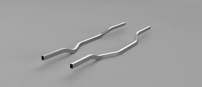
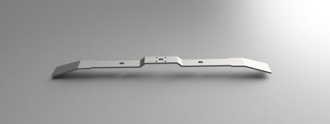
The CAD model of the ladder chassis was created using Autodesk Fusion 360 software. The model is designed by following the Design Methodology guidelines. The initial concept is for a longitudinal single rail with a rectangular box shape. Thedrawn longitudinal rail is thin at the front end and broad at the back end, as shown in Figure 1. Bends are sketched near the position where the wheels are installed. The design extrude is done using the 'extrude'optionwiththelengthoftheMUVspecifiedonce it has been designed in Sketcher. The Shell command' is used,togetherwithathicknessof6mm,tomakeita'box section.' The longitudinal rail is built with the necessary bracketsandholdsforfutureuse.Whenthemirror'option is selected, another longitudinal rail is formed at a distanceequaltotheMUV'swidth.[21]
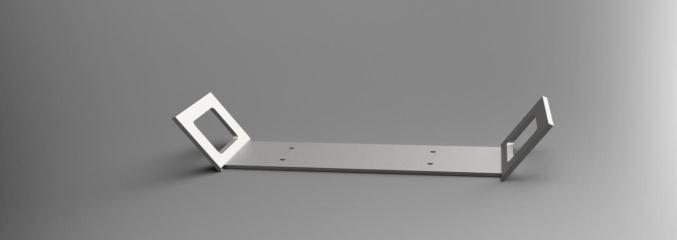
The same tools are used to design the cross member (as shown in Figure). These are designed to give ladder chassis strength. A 'pocket' tool is used to make holes. All of the other components are built in the same way. The filettoolisusedtosmooththesharpedge
International Research Journal of Engineering and Technology (IRJET) e ISSN: 2395 0056
Volume: 09 Issue: 06 | June 2022 www.irjet.net p ISSN: 2395 0072
The Manipulation tool,' 'coincidence constraint,' and 'offset'toolsareusedtoputallofthepiecestogether.The above mentioned tools are used once the component has been imported into the assembly section. The component ismanipulatedintothedesiredplaceusingamanipulation tool.Whennecessary,theoffsettoolisutilizedtomaintain a fixed spacing between the components. All other componentsareassembledusingthesamemethod.
thechassis suffers less.strain values, depending on the loadingconditions.
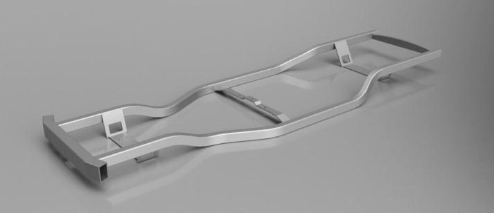
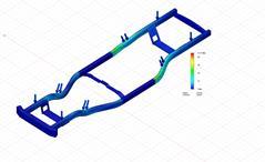
Figure 4: 3 D modelofchassisdesigned
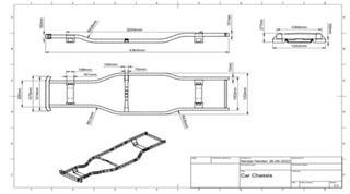
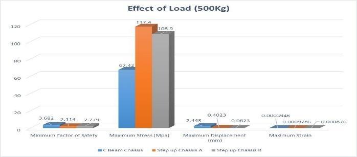
Figure 6.: PostsimulationComparisonat500kgload
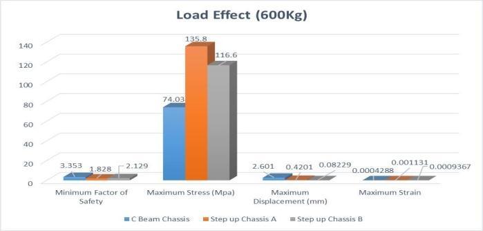
Figure 7: PostsimulationComparisonat600kgload
Figure
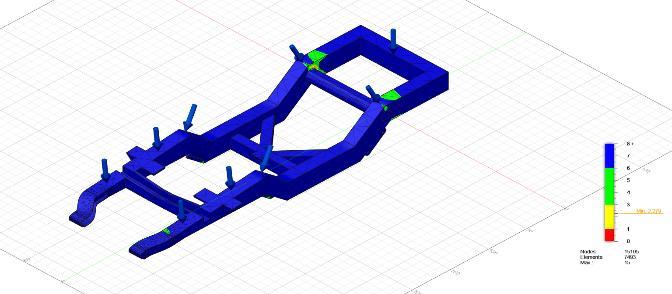
The designed chassis model is now analyzed for its structural testing, as in testing for Minimum Factor Of Safety(FOS), Maximum Displacement simulation testing, Maximum Stress testing for First Principle, Third Principle and Von Mises, also Maximum Strain testing. Thefollowingresultsarethencomparedwithpre existing urban chassis of two different structural designs and tabulated.
As indicated in the figures below, the obtained outcomes are the physical behavior of.the chassis after applying the stated parameters, namely the value of the minimum factor of safety, max stress, max displacement, & max strain. When the thinnest material's safety factor values are taken into account, the carbon steel chassis is determined to be the strongest among all offered materials based on the overall data. The observed stress and strain values support this trend, demonstrating that the structure can withstand larger stresslevels while
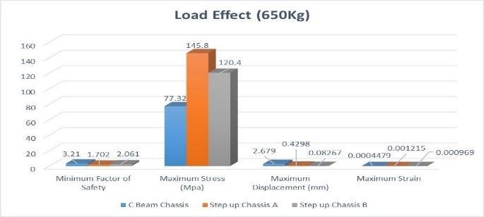
Figure 8: PostsimulationComparisonat650kgload
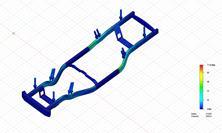
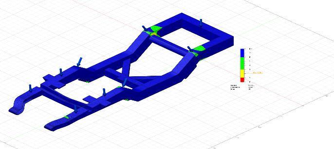
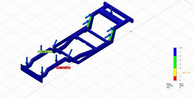
Sincethetestingisdoneforthreeloadingconditionsie;at 500kg, 600kg and 650kg we consider the results produced at 500kg and 650kg loading condition.The Structural displacement in the models conducted are displayedinthefiguresbelow.
International Research Journal of Engineering and Technology (IRJET) e ISSN: 2395 0056
Volume: 09 Issue: 06 | June 2022 www.irjet.net p ISSN: 2395 0072
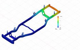

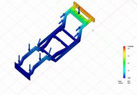
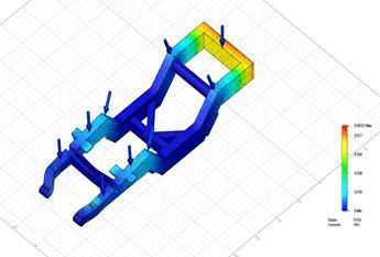
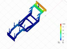
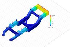
Figure 9.1: CbeamDisplacementat500kg
Figure 9.2:CbeamDisplacementat650kg
After numerous specified loads are applied to the chassis, according to the simulation result in this scenario, different locations and values of maximum displacement occur. When,load is 500kg, the max displacement value is 2.443mm, which is placed around the back of the chassis, andtheotheris2.679mm,asillustratedinFigure,whichis positioned on the back side of the largest force applied (650kg). The displacement.value reflects how far the structure has moved from its initial location asa resultof theimposedload.
Figure 9.6: StepupchassisBdisplacementat650kg
9.3:
upchassisAdisplacementat500kg
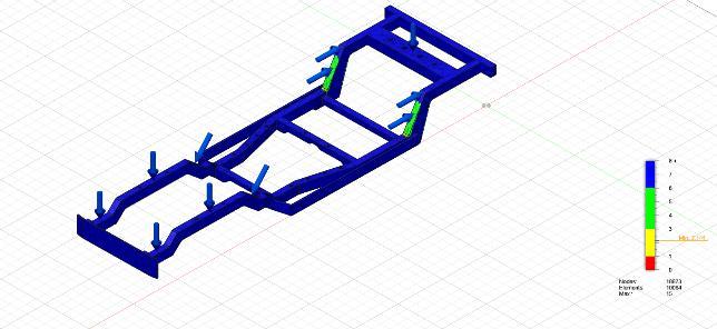
The following comparisons are made with the 'Step up Chassis A' and 'Step up Chassis B' versions, respectively. Using the Step up Chassis A model, defined loads are appliedtothechassis,anddifferentlocationsandvaluesof maximum displacement occur based on the simulation results in this scenario. As indicated in Figure above, whenload is 500kg, the max displacement value is 0.4023mm, which is located around the back of chassis, and the other is 0.4298mm, which will be located on the back side of the largest force applied (650kg). According to the simulation result in this scenario, when numerous specified loads are applied to the chassis, different locations and quantities of maximum displacement occur. When load is 500kg, the maxdisplacement value is 0.0823mm,whichisplacedaroundthebackofthechassis, and0.08267mm,whichwillbelocatedonthebacksideof thelargestforceapplied(650kg),asshowninFigure. The developed chassis, in comparison to the Step up chassis types, exhibits a variety of behaviors connected to operational elements such as load combination and internal characteristics such as structural thickness and material. The type of material utilized has an influence
International Research Journal of Engineering and Technology (IRJET) e ISSN: 2395 0056
Volume: 09 Issue: 06 | June 2022 www.irjet.net p ISSN: 2395 0072
that increases the value of the factor of safety and maximum stress while decreasing the value of max displacementandmaxstrain.
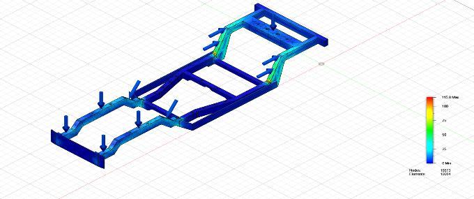
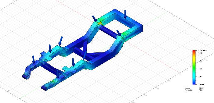
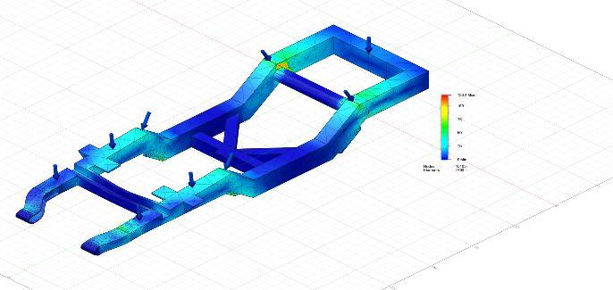

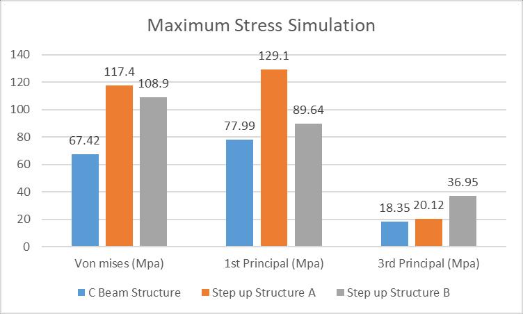
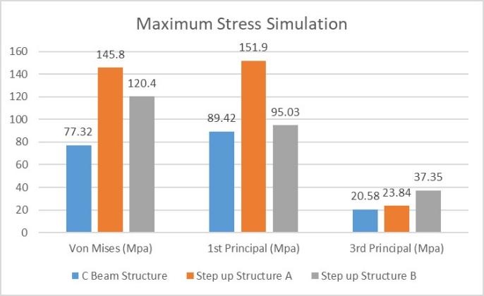
4.2 Stress Simulation of C beam Chassis and Stepup Chassis for different Load Condition
maximumstressis89.42MPawhichwillbelocatedonthe same side, of the largest force applied shown in Figure. Similarly for Step upchassisAandBthe maximum stress at500kgloadis121.9Mpa and89.64Mpa, for650kgload the maximum stress is 151.9 Mpa and 95.03 Mpa. The stress number indicates that a higher applied load causes the structure to shift more from its initial position. This has also been conducted for the following Models in comparison.
Figure 10.1: CbeamStressat500kg
Figure 10.5: StepupchassisBStressat500kg
Figure 10.2: CbeamStressat650kg.
Figure 10.3: StepupchassisAStressat500kg
Figure 10.6: StepupchassisBStressat650kg
Figure 10.7:Maximumstressesat500kg
Figure 10.4: StepupchassisAStressat650kg
Based on the stress simulation result of these cases, different location. And after many selected loads, that are applied to the chassis, the maximum stress value occurs.. When the. Load is 500kg for the C beam chassis, the maximum stress is 77.99 MPa, while at 650kg the
International Research Journal of Engineering and Technology (IRJET) e ISSN: 2395 0056
Volume: 09 Issue: 06 | June 2022 www.irjet.net p ISSN: 2395 0072
Figure 10.8:Maximumstressesat650kg
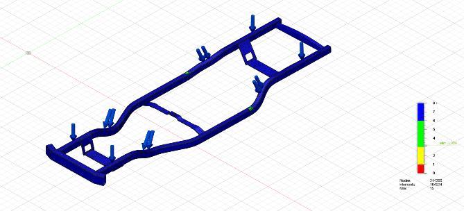
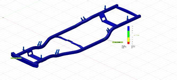
4.3 Factor of Safety Simulation of C beam Chassis and Step up Chassis for different Load Condition
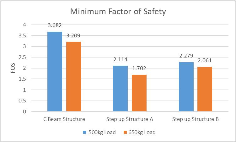
Figure 11.4: StepupChassisAFOSat650kg
Figure 11.1: CbeamFOSat500kg
Figure 11.2: CbeamFOSat650kg
Figure 11.3: StepupChassisAFOSat500kg
Figure 11.5: StepupChassisBFOSat500kg
Figure 11.6: StepupChassisBFOSat650kg
Figure 11.7:MinimumFOSat500kgand650kg
Thesimulationresultforthiscase,istoverifytheFactorof SafetyforeachmodelofChassis.Loadisappliedalongthe regionsofstressinfluenceas,whentheloadis500kg,the FOSvalueis3.682whiletheotheroneis3.209thehighest forceapplied(650kg)showninFigure.TheFOSoftheStep upchassisAmodelare2.114and1.702atmin(500kg)and max(650kg) loading conditions, similarly for the Step up
International Research Journal of Engineering and Technology (IRJET) e ISSN: 2395 0056
Volume: 09 Issue: 06 | June 2022 www.irjet.net p ISSN: 2395 0072
chassis B its 2.279 and 2.061 at 500kg loading condition and 650kg loading condition. The higher the value of FOS ie; above 3, the safer is the structure under loading and closerthevalueisto1,thefareritistobeingsafe.
Based on the results obtained, dueto operational And internal factors, manyobservationsaremade.The type of material used has an effect on the safety factor and maximum stress while lowering maximum displacement and maximum strain. Because a material with a higher yield strength, Low Carbon Steel A36, is used in this instance, the strength parameter increases. The influenceof frame thickness isdemonstrated by the increasing tendency of maximum.stress, maximum.displacement, and maximum.strain, as well as the decreasing tendency of the safety factor with decreasing frame thickness. The tension will rise as thearea of the frame decreases, and the displacement will rise as the thin frame will have less material to carry the load. Thin frames also shorten the chassis, increasing strain while lowering the safety factor. The result of applied loading on the specified vehicle chassis is an increasein maximumstress, maximumdisplacement, and maximumstrain, while the safety factor value falls as the loadincreases. the frame of the vehicle. The simulations conductedhavebeentabulatedtoindicatethattheCbeam chassis tends to give favorable results in comparison to theotherStepupchassismodels.The conclusionthatcan be drawn from this is that the designed model is the betterandsaferstructuretobeartheweightofthevehicle throughout its functional use. Future structural optimization research is highly encouraged to be carried out.Thesimulationdatafromthisstudyisagoodstarting point for determining the best chassis construction combination.
1. Kalghatgi, G. (2018). Is it really the end of internal combustion engines and petroleum in transport?. AppliedEnergy,225,965 974.
2. Design and Analysis of A Ladder Frame Chassis for Static andDynamic Characteristics Obed Lungmuana Darlong,Assoc.Prof.ByraReddy,Assoc.Prof.Dadapeer B Assistant Professor, Mechanical Engineering Department, RMD Sinhgad School of Engineering, Maharashtra,India
3. Structural Assessment Of Alternative Urban Vehicle ChassisSubjectedToLoadingAndInternalParameters
Using Finite Element Analysis Angga K. Ary, Aditya R. Prabowo,FitrianImaduddin,DepartmentofMechanical Engineering, UniversitasSebelasMaret, Jl. Ir. Sutami 36A,Surakarta,CentralJava57126,Indonesia
4. Design and Crash Analysis of Ladder Chassis Monica Muthyala.
5. Structural Analysis Of A Ladder Chassis Frame Vijay Patel, LDRP Institute of Technology and Research, Ruhulamin Patel Government Engineering College, Dahod April2012
6. StructuralAnalysisOfChassis:AReview SurajBPatil M.E, Mechanical Engineering Department, RMD Sinhgad School of Engineering, Maharashtra, India, Dinesh G Joshi Assistant Professor, Mechanical Engineering Department, RMD Sinhgad School of Engineering,Maharashtra,India
7. Stressanalysisofatruckchassiswithrivetedjointsby Cicek Karaoglu*, N. Sefa Kuralay, 2002.Department of Mechanical Engineering, DEU Faculty of Engineering, 35100 Bornova, Izmir, Turkey ,Finite Elements in AnalysisandDesign381115 1130
8. The effect of connection plat thickness on stress of truck chassis with riveted and welded joints under dynamic loads is carried out by M. zehsaz, Vakili Tahami and Esmaeili. Asian Journal of applied Science 2(1):22 35,ISSN1996 3343.[3]DynamicAnalysisofa ModifiedTruckChassisbyMohammadRezaForouzan., Majlesi Journal of Mechanical Engineering, Vol. 3/ No. 4/Summer
9. ShiCQ,DingHM,YangSM.Finiteelementanalysisof truck frame and effects of cargo body on frame performance.AutomobileTechnology
10. “Assessment of Fuel Economy Technologies for Light DutyVehicles.”[Online].[Accessed:03 Aug 2018].
11.“Construction Mechanic Basic Chapters 14. [Accessed: 27 Aug2018].
12.S. N. R. H. Kumar, “Automobile Chassis and Body Engineering.”[Online][Accessed:13 Aug 2018].
13.A. Anand, “Torsional analysis of the chassis and its validationthroughFiniteElementAnalysis,”p.7.
14.Ms. A. E. Chambers, Mr. S. A. Rodriguez, Mr. R. M. Walsh, and Dr. D.Wootton, “Development of a Test Stand for Determining the Torsional Rigidity of a FormulaSAESpaceFrame.
15.A. Tomar and D. Singh, “Modeling and Analysis of a Chassis Frame by Using Carbon Fiber and E Glass EpoxyasCompositeMaterial:AComparativeStudy.”
16.A.H. Kumar, V. Deepanjali, Design & analysis of automobile chassis. Int. J. Eng. Sci. Innov.Technol. (IJESIT)5,187 196(2016)
International Research Journal of Engineering and Technology (IRJET) e ISSN: 2395 0056
Volume: 09 Issue: 06 | June 2022 www.irjet.net p ISSN: 2395 0072
17. J. Rajpal, R.S. Bhirud, A.K. Singh, A.V. Hotkar, S.G. Thorat, Finite element analysis and optimization of an automobile chassis. Int. J. Eng. Res. Technol. (IJERT)3,2075 2082(2015)
18. J. Rajpal, S.G. Thorat, B.S. Basavaraj, S. Kothavale, S.S. Hatwalne, Design considerations for automobile chassis for prevention of rolling over of a vehicle. Appl.Mech.Mater.6,41 49(2014)
19. Vehicle Chassis Analysis: Load Cases & Boundary ConditionsForStressAnalysis AshutoshDubeyand VivekDwivedi
20. Electric Vehicle Chassis Design and Structural AnalysisbyusingCADandCAETechniques D.Arun, D.V.Paleshwar,K.Sainath.
21. ModeShapeAnalysisofEV BusChassiswithReverse Engineering Method N Nazaruddin, A Syehan , G Heryana,MAdhityaandDASumarsono
22. Structural and Modal Analysis on A FrameLess Chassis Construction of Heavy Vehicle for Variable Loads K.P.Sirisha,R.LalithNarayana,A.Gopichand, Ch.Srinivas,G.RamBalaji
23. Structural Analysis of Ladder Chassis for Higher Strength AbhishekSingh,VishalSoni,AdityaSingh
24. Structural Analysis of Ladder Chassis Frame for Jeep Using Ansys Vishal Francis , Rajnish Kumar Rai , Anup Kumar Singh , Pratyush Kumar Singh , HimanshuYadav
25. Stress Analysis of Ladder Chassis with Various Cross Sections KamleshY.Patil,EknathR.Deore
26. Shape Optimization of Automobile Chassis Aayush Chugh,RachitAhuja,SukritiRanjan
27. Dynamic Analysis and Design Modification of a LadderChassisFrameUsingFiniteElementMethod ShrinidhiRao,AjayBhattu
28. Design & Analysis Of Automobile Chassis A.Hari Kumar,V.Deepanjali
29. AReview on DesignandAnalysisofLadder Chassis ScholarShubhamAgrawal,Prof.ArunPate
30. Structural Analysis of Ladder Chassis Frame for car Using Ansys S.Sivaraj , A.Hazemohzammed , M.Yuvaraj,N.Karthikeyan,V.Murugan