International Research Journal of Engineering and Technology (IRJET) e ISSN: 2395 0056

Volume: 09 Issue: 06 | Jun 2022 www.irjet.net p ISSN: 2395 0072
International Research Journal of Engineering and Technology (IRJET) e ISSN: 2395 0056
Volume: 09 Issue: 06 | Jun 2022 www.irjet.net p ISSN: 2395 0072
Chaitanya S Kannao1 , Dr. Sanjay S Bhagwat2
1M.E (CAD/CAM) Department of Mechanical Engineering Babasaheb Naik College of Engendering, Pusad 445204, India 2Associate Professor Department of Mechanical Engineering Babasaheb Naik College of Engendering, Pusad 445204, India ***
Abstract - The Engine cylinder is one of the essential engine components, which is subjected to over the top temperaturedifferencesandthermalstresses.Inaircooled I.Cengines,extendedsurfacescalledfinsareprovidedatthe peripheryofenginecylindertoincreaseheattransferrate. Fins are set on the surface of the cylinder to improve the quantity of heat exchange by convection. The cooling mechanismoftheair cooledengineismostlydependenton thedesignofthefinonthecylinder.Coolingfinsareusedto increasetheheattransferrateofspecifiedsurfaces.Thefin parameters like length, pitch, thickness, fin number, widenessandmaterialsarehavinggreatinfluenceonheat transfer rates, so if the sole purpose is to increase heat transferrate,thentheshapeoffinwillplayacrucialrolein increasing heat loss capacity of the cylinder block of the samesizeandmaterials.Firstofall,ananalyticalcalculation waremadetofindtheamountofheatlosstothroughfins theoretically. The inner wall temperature was taken approximately2000Cwhichisrequiredformaintainingthe cycleoftheengine.Outerwalltemperatureandfinsurface temperature ware calculated theoretically &; computationally. From literature survey circular &wavy shapefinsareconsideredfortheanalysis.Also,aluminium, aluminium 6061 and aluminium 2014 are selected as material for comparative analysis with above mentioned shapes. CAD models were built using SOLIDWORKS 2020 andanalysisoffinswerecarriedoutinANSYS2022Student version.Theresultsfoundfromtheanalysisshowsthatthe improvedperformanceofwavyfinsisobtainedascompared tothecircularfins.
The cooling of hot surfaces by means of metal fins can be achieved bytwoways i.e.,oneinvolving the convection of heat from the fin surfaces by air stream and the other by conductionofheatthroughthefinstofinsurface.Therateat whichheatisconveyed fromafinsurfacebyairstreamis usually expressed as a surface heat transfer coefficient. Almost all modern motorcycle engines use liquid cooling exceptformotorbikeengines.Althoughitismoredifficult for air cooling than liquid cooling to effectively cool an engine,constructionofanair cooledengineissimpler.Inan air cooled engine, the fins conduct heat away from the cylinderandtransferittotheair.Therefore,itisimportant for air cooled engines to utilize fin for effective engine
coolinganduniformtemperatureinthecircumferenceofthe cylinder.WeknowthatincaseofICengines,combustionof airfuelmixturetakesplaceinsidetheenginecylinder and hotgassesaregeneratedinsidethecylinderoftwo wheeler temperatureis3000to10000C.Duetothishightemperature the gasket or film are burned, fins help to reduce the temperaturearound1800 2500 C.Thedesignofmetalfins increasesthesurfaceareaoftheengineandthusimproves thecoolingratethroughconvection.Toomuchcoolingofthe cylinderreducesitsthermalefficiency,sotheobjectofthe cooling system is to keep the engine running at its most efficient operating temperature. It is to be noted that the engine is quite inefficient when it is cold and hence the cooling system is designed in such a way that it prevents coolingwhentheengineiswarmingupandtillitattainsto maximum efficient operating temperature, then it starts cooling.Thedesignoftheair cooledengineinvolvesmany aspectsofengineeringconsiderations,suchascoolingrate, totalmass,geometryrestrictions.
Internalcombustionenginesrejectmostoftheheatcontent ofthefuelwhichtheyburninthatpartwhichtheyturninto power.Theimportanceoftheheatwhichisrejectedisoften not recognized, but this heat is the cause of most engine troubles and is the basic determinant of the rating of an engine. Part of the heat which is rejected by the engine is carried away by the exhaust gas and the remaining must pass through the metallic walls which surround the combustionchamberthatis,thepiston,thecylinderwalls, thepistonrings,injector,sparkplugs,andexhaustpassages. Theheatwhichisrejectedthroughthemetallicpartsraises their temperatures and in passing through these parts expands,weakens,andstressesthem.Eachparthasalimited capacity to flow heat through itself and in general more drastic cooling creates internal stresses in the materials. Thus,oneoftheprincipalobjectivesinthedevelopmentof any internal combustion engine is to obtain the highest possible thermal efficiency to reduce the flow of heat throughtheengineparts.
International Research Journal of Engineering and Technology (IRJET) e ISSN: 2395 0056
Volume: 09 Issue: 06 | Jun 2022 www.irjet.net p ISSN: 2395 0072
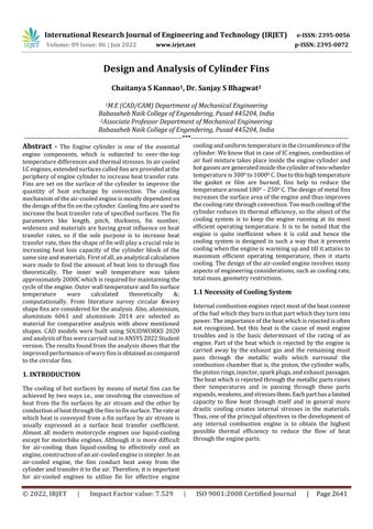
Necessity of cooling system in I.C engines is all the heat createdbytheignitionoffuelintheenginechambersisn't changedoverintovaluablepoweratthecrankshaft.Valuable workatthecrankshaft=25 40%Losstothecylinderwalls = 10 30 % Loss in exhaust gasses = 20 45 % Loss in friction&radiation=10 35%.Itisseenthattheamountof heatgiventothechamberdividersisimpressiveandifthis heatisn'texpelledfromthechambers,itwouldbringabout the pre ignition of the charge. Moreover, the oil would likewise consume with extreme heat, along these lines causingtheseizingofthecylinder.Abundanceheatingwill likewise harm the chamber material. To avoid thermal breakdownofthelubricatingoil,itisnecessarytokeepthe cylinderwalltemperaturesintherangeof180° 200°C. As lubricationtechnologyimproveswiththequalityofoils,than maximumallowablewalltemperaturecanbemaintained.
Aircooledsystemisgenerallyusedinsmallenginessayup to15 20kWandinaero planeengines.Inthissystemfinsor extended surfaces are provided on the cylinder walls, cylinderhead,etc.Heatgeneratedduetocombustioninthe enginecylinderwillbeconductedtothefinsandwhenthe air flows over the fins, heat will be dissipated to air. The amountofheatdissipatedtoairdependsupon:
(a)Amountofairflowingthroughthefins.
(b)Finsurfacearea.
(c)Thermalconductivityofmetalusedforfins
Followingaretheadvantagesofair cooledsystem: Radiator/pumpisabsenthencethesystemislight.
Inthecaseofawater coolingsystemthereareleakages, butincaseofair coolingsystem,therearenoleakages.
Coolantandantifreezesolutionsarenotrequired.
Thissystemissuitableincoldclimates,aswatermaybe getfrizzedatlowertemperature.
Comparativelyitislessefficient.
Itcanbeappliedonlytothesmallandmediumengines.
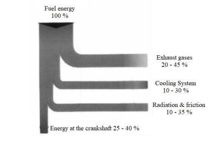
Afinisasurfacethatextendsfromanobjecttoincreasethe rate of heat transfer to or from the environment by increasing convection. The amount of conduction, convection, and radiation of an object determines the amount of heat it transfers. Increasing the temperature difference between the object and the environment, increasing the convection heat transfer coefficient, or increasingthesurfaceareaoftheobjectincreasestheheat transfer.Sometimesitisnoteconomical,oritisnotfeasible tochangethe first two options.Adding a fin to the object, however,increasesthesurfaceareaandcansometimesbe economicalsolutiontoheattransferproblems.Thesurface area over the cylindergets bigger by meansof fins. These fins are either cast as an integral part of the cylinder or differentfinnedbarrelsareplacedoverthecylinderbarrel. Sometimes particularly in aero engines, the fins are machinedfromtheforgedcylinderblanks.Asarule,thefins areusuallymadeofaboutthecylinderwallthicknessattheir
International Research Journal of Engineering and Technology (IRJET) e ISSN: 2395 0056
roots,tapering downtoaboutone halfthe root thickness. Thelengthofthefinsvariesfromone quartertoone thirdof the cylinder diameter. The distance between the two fin centersisaboutone quartertoone thirdoftheirlength.The total length of the finned cylinder barrel is from 1 to 1½ timesthecylinderbore.
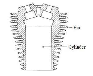
According to heat transforming necessity fins can be selected.Thevarioustypesoffinsareasshowninfig1.3 Parabolicfin
fin
Triangularfin
Rectangularfin
Trapezoidalfin
Fig. 1.3 : DifferentTypesofFins
The cooling mechanism of the air cooled engine is mostly dependent on the design of fin cylinder head and block. Fig.1.4,showstheoverallheattransferprocessfromgasses withinthecylinderthroughthecombustionchamberwallby conductionmodeandfinnedsurfacestotheexternalairflow byconvectionmodeTheconductionheattransferfrominner walltofinsurfaceisgivenas[7] �1 =�(�� −���� )...(1)
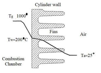
Thermal conduction is a mechanism of heat propagation from a region of higher temperature to a region of lower temperature within medium (solid, liquid or gaseous) or between different mediums in direct physical contact. Conductiondoesnotinvolveanymovementofmicroscopic portions of matter relative to one another. The thermal energymaybetransferredbymeansofelectronswhichare freetomovethroughthelatticestructureofthematerial.In
addition,oralternatively,itmaybetransferredasirrotional energy in the lattice structure of the material. Thermal conductionisessentialduetorandommolecularmotion;the conceptistermedasmicroformofheattransferandusually referred to as diffusion of energy The convection heat transfer from fin surface to atmosphere air by free and forcedairisgivenas � 1 =ℎ� (�
Thermal convection is the process of energy transport affected by the circulation or mixing of a fluid medium. Convectionispossibleonlyinafluidmediumandisdirectly linkedwiththetransportofthemediumitself.Macroscopic particlesofafluidmovinginspacecausetheheatexchange, andthusconvectionconstitutesthemacroformoftheheat transfer. The effectiveness of heat transfer by convection depends largely upon the mixing motion of fluid. With respecttoorigin,therearetwotypesofconvection,namely freeconvectionandforcedconvection.Innaturalconvection flowoffluidiscausedbydensitydifferencewhileinforce convectionfluidflowcausedbyPump.
1.4
[7]
Thisprojectdealswithdesignandanalysisofvarioustypes of fins with different material i.e. Aluminium, Aluminium 6061&Aluminium2014.
Biermann Arnold E. & Pinkel Benjamin (1934), [1] presentedfindimensionsformaximumheattransferwitha given amount of material for variety of conditions for air flow and metals. Concluded that the value of surface heat transfercoefficientvariesmainlywithairvelocityandspace betweenthem.Theeffectof otherfindimensionsissmall. They used the theoretical formula for calculating the heat dissipatedfromfinnedcylinderchecksfairlycloselytheheat dissipationexperiment.
Cramer Robert (1967) [2] developedmethodsofcalculating the heat rejection of internal combustion engines so that these quantities can be used in selecting radiators and oil
Volume: 09 Issue: 06 | Jun 2022 www.irjet.net p ISSN: 2395 0072 © 2022, IRJET | Impact Factor value: 7.529 | ISO 9001:2008 Certified Journal |
International Research Journal of Engineering and Technology (IRJET) e ISSN: 2395 0056
Volume: 09 Issue: 06 | Jun 2022 www.irjet.net p ISSN: 2395 0072
coolers. The importance of heat which is rejected, though oftennotrecognized,isthatitisthesourceofmostengine troubleandalsoisthebasicdeterminantfortheratingofan engine.Partoftheheatwhichisrejectediscarriedawayin the exhaust gasses, the remaining passes through the metallicwallsoftheengine,causingexpansionandinternal stressintheparts.Alsodiscussedinput outputrelationships intheengineaswellascalculationsforheatlossandengine cooling phenomena. The methods developed give some insight into the thermodynamic efficiency of the internal combustionengine.
Perlewitz R. E., Lon Mooney & Wm. Kalweit (1967) [3] made basic consideration to make optimal use of the material in the cylinder to obtain maximum heat transfer. Thetrapezoidalfinapproachestheidealconstructionandis more effective than either the rectangular or triangular types. This fin can be cast with comparative ease and has good strength characteristics. Many thin cylinder fins are betterthanafewthickfins,manyshortfinsarebetterthana fewlongfins,providingthesameamountofmaterialisused andinengineaboveall,provisionshouldbemadeforforeign materialiftheengineisruninadirtyenvironment.
Gale Nigel F. (1990) [4] discussed some of the design optionsfordieselenginecylinderheads.Sincethereareno firm rules concerning cylinder head design, it is better to avoid making firm conclusions on the choices available to designers.However,itisclearthatcertaindesignfeatures providefarmoreacceptablecompromises.Theusefulnessof theimpulseswirlmeteronaflowbenchcanbeextendedto separatingswirlintotwotypes:helicalanddirectedswirl. Analysis of these two types of swirls can reveal potential improvementsinportefficiency.
Biermann Arnold E. & Herman H. Ellerbrock (1993) [5] performedananalysistodeterminetheproportionoffins madeofaluminium,copper,magnesium,andsteelnecessary to dissipate maximum quantity of heat for different fin widths,finweights,andairflowconditions.Theanalysisalso concerns determination of the optimum fin proportions whenspecifiedlimitsareplacedonthefindimension.
Zhang Yong et al (1998) [6] discussedanimportanceoflow heatrejection(LHR)techniquetoreducethethermalloads and heat rejection in the field of internal combustion engines. In heavy mechanical and thermal loads, cylinder headsarethemostcomplicatedpartsandthekeypointof theLHRtechniqueapplicationinengines.Andpresentedthe researchingworkoftheLHRcylinderheadanditsstructure also presented the structure of a LHR cylinder head for vehicleengines.
Menon Zakirhusen K et al (2005) [7] conductedparametric studyonfinheattransferforaircooledmotorcycleengines in this the fin profile and fin array parameters could be optimizedinabetterwaybynumericalsimulationmethods.
CFD can be used to determine optimal values of the fin parametersbeforedesignprocess.
Yoshida Masao et al (2006) [8] conductedanexperimentto optimizefinlayoutofaircooledenginecylinderinairstream. In order to permit the development of design data, an experimental cylinder was developed having variable fin pitchandnumberoffincapability.Usingtheexperimental cylinder,theeffectsofthenumberoffins,finpitchandair velocityoncylindercoolingwereinvestigated.
Tripathi Pradeep Mani et al (2014) [9] presentedapaper on thermal analysis of the cylinder head assembly of the four stroke engine. They created a detailed FE model consistingofmainpartsofthecylinderheadassemblyandit includesadescriptionofthermalandmechanicalloadsand contactinteractionbetweenitsparts.Themodelconsidersa temperature dependency of a heat transfer coefficient on wall in cooling passages as fins. They carried out analysis using the FEM program. The finite element method is appliedtofindthetemperaturedistributionfieldfromthe partsofthecylinderheadofSIengine.
Deshpande A.C. et.al (2015) [10] investigatedtheeffecton heattransferratebychangingthecross section,finpitch,fin Materialandfinthickness.Thevehiclestheyconsideredhave singlecylinderaircooledengineswithasetofrectangular fins mounted on the cylinder block. They measured temperaturegeneratedatsteadystatefromthefinsurface throughexperimentsandusedthevalueaskeyparameter, heatdissipatedandcalculatedheatfluxthroughfinsusing empiricalformulations.TheyalsovalidatedbyusingtheFEA approach.
Yellaji Bade et.al. (2017) [11] conductedthermalanalysis on heat distribution in fins of compressor cylinder by varyingprofileusingFEM.Theyalteredgeometricalshapes offinsforanalysisandselectmosteffectivecoolingfin.They have work on rectangular, triangular, concave & convex profilefinofaluminiumnitrideandaluminiumalloyA204 preferred for analysis. The parameters for analysis heat transfer rate through fin, fin efficiency and effectiveness throughfreeandforcedconvectionheattransfermode.The resultsobtainedwithconcavefinwithmaterialaluminium alloyA204isbettersinceheattransferrateofthefinismore. By using concave fins, the weight of the fin body reduces comparedtoexistingrectangularenginecylinderfin.
N. Arul et.al. (2017) [12] conducted experimental and computational analysisofvarioustypesoffins.UsingCFD softwarethefluidanalysisisdonewithexistingdesign.The dimensions of the cylinder length, cylinder thickness, cylinderinnerandouterdiameterareinitializedbyustoa certainvaluecorrespondingtotheexistingavailabledesign.
K. Sathishkumar et.al (2017) [13] computationalanalysisof heattransferthroughfinswithdifferenttypesofnotchesin whichthefins with various configurations were modelled
International Research Journal of Engineering and Technology (IRJET) e ISSN: 2395 0056
Volume: 09 Issue: 06 | Jun 2022 www.irjet.net p ISSN: 2395 0072
usingCREO2.0andanalysesaredonebyusingCFD Fluent inordertofindouttheheattransferrate.
Sorathiya A. S. et.al. (2017) [14] presented the augmentation of heat transfer coefficient for varying fins configurationofcylinderblockofSIengine
Kumar Rajat et.al. (2020) [15] studiedenhancementofthe thermal properties by shifting geometry, material, and designoffins.Thethermalanalysisoffinsbymodifyingits certainparameterssuchasgeometryandplatefinsandpin fins has been completed and by observing the analysis results, they say using conical draft pin fins with material aluminiumalloy1060isbettersincethetemperaturedrop and the heat transfer rate in a conical draft pin fins much more,comparedtoplatefin.
Shareef, S. K. Mohammad et.al. (2021) [16] presented numerical investigation of thermal properties of engine cylinderbyvaryinggeometrypropertiesmaterialandprofile ofcylinderusingANSYSworkbench.
Abbood M. H. et.al. (2021) [17] conductedinvestigationon theeffectsoffingeometryonmotorcyclecylindercoolingby addingeightfinswithdifferentshapesaroundthecylinder. TheyuseFluentsoftware(ANSYS19.0)forinvestigation.In investigation theyvariedReynoldsnumbers(4,6,and8 x 104)underconstantheatflux(6,12,25kW/m²).Fourtypes of fins, square, circular, elliptical, and air foil, all with the samethickness(5mm),pitchgapbetweeneachfin(3mm), andsurfacearea(0.0745m²)wereinvestigated.Themetal usedforthefinbodieswasaluminiumalloy,withathermal conductivityof237W/m K.Theworkingfluidusedwasair. Theyconcludedthatthebestcasewasseeninthecylinder withsquarefins, whichobtainedthehighestvalueofheat transfer coefficient, and the rate of the heat transfer increaseswhentheReynoldsnumberincreases.
Theaimofthisprojectistodesignandanalysisofcylinder fins, for heat deception by changing the geometry and materials.
1.CreationofconceptualCADmodelforstudy.
2. To enhance the heat transfer rate by making following changes
i)Changethegeometryoffinsi.e.circular&wavyshapefins inwhichthethicknessoffinwaskeptconstanti.e.2mm
ii) Change the material of the fin and selecting various materials for further process i.e. Aluminium, Aluminium 6061&Aluminium2014
4.Evaluatefinsurfacetemperaturecomputationally.
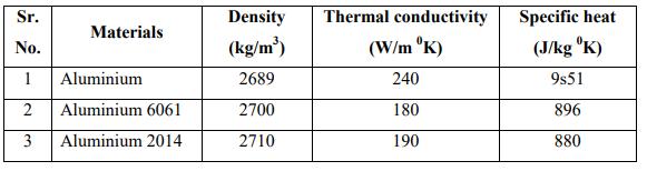
Table 3.1 : Selectionofmaterialandtheirproperties.
Fordesignwehaveselectedthe125ccenginewasselected anditsspecificationsareasfollows,
Table 4.1 : SpecificationsofModel
Modelname HondaShine
CC 125 Stroke(mm) 58 Bore(mm) 52 Numberoffins 6 Finpitch(mm) 10 Finthickness 2.5 Finmaterial AlAlloy Positionoffinsw.r.tcylinderaxis Perpendicular
1.Thicknessofcylinder=0.045D+1.6mm = 0.045 × 52 + 1.6 mm , . =3.64mm . . =4mm
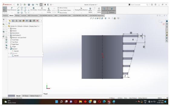
2.Maximumlengthoffin=22mm
3.Minimumlengthoffin=7mm
4.Circularfinprofileshave2mmthickfinsweremodelled.
5.Thenumberoffinsforeachmodelare6.
6.Thedistancebetweenthetwotopsurfacesofthefinsis maintainedat10mm.
7.Theenginecylinder'slengthis58mm;theouterandinner borediametersare60and52mm.
4.2 Steps of involved in CAD Modelling
4.2.1 Circular Fins
ForCADmodellingSOLIDWROKS2020softwarewasused. The SOLIDWORKS® CAD software is a mechanical design automation application that designers quickly sketch out
2022, IRJET | Impact Factor value: 7.529 | ISO 9001:2008 Certified Journal
International Research Journal of Engineering and Technology (IRJET) e ISSN: 2395 0056
ideas, experiment with features and dimensions, and producemodelsanddetaileddrawings.
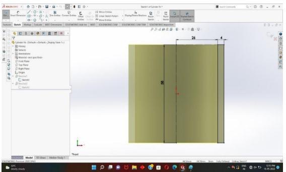
Step 1:SelectFrontPlaneandcreated2Dsketchrectangleof 58 x 60 and converted to 3D with revolve command, as showninFig.4.1&4.2
Step 3: Convertthesketchinto3DbyRevolvecommand,as showninFig.4.4
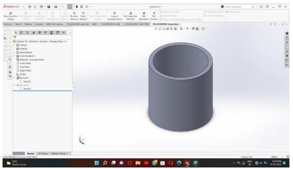
Fig. 4.1 : Created2DSketchofCylinder
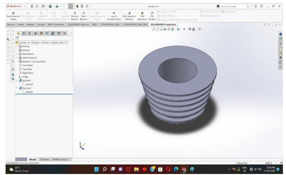
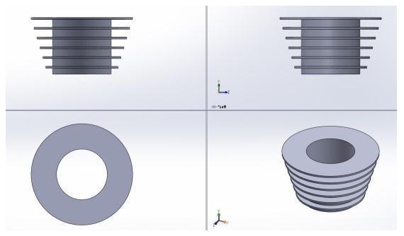
Fig. 4.4 : ConverttheSketchinto3DbyRevolveCommand Step 4 : Finalsketchofcircularcylinderfinisasshownin fig.4.5
Fig. 4.2 :3DwithRevolveCommand
Step 2: Sketch is made for extended surfaces i.e fins as showninfig4.3
Fig. 4.5 : FinalsketchofCircularCylinderFin
Fig. 4.3 : SketchIsMadeforExtendedSurfaces
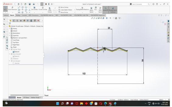
Convectiveheatflowcanbeenhancedbyalteringtheshape of fin to wavy shape. The design of wavy fin involves the parameterslikefinlength,finwidth,finthickness,waviness angle,finpitchandnumberoffins.Generally,finlengthand numberoffinsarefixedbycylindersize,finwidthwill be decidedbyheatlossrequirementaswellasspaceavailable forthecylinderinmotorbikewhilethicknessmustbekept less as far as possible for faster removal of heat, but manufacturinglimitationandstrength ofcylinder finsput limitation as minimum as 2 mm or more. From the above discussion, it is clear that only two parameters i.e Fin wavinessangle.&Finpitchareneededtobedesignedand optimize for better heat transfer coefficient. Wavy fin has pitch four times more than its thickness and 200 of wave angle with 25 mm wavelength are recommended by SorathiyaA.S.[17]
Volume: 09 Issue: 06 | Jun 2022 www.irjet.net p ISSN: 2395 0072 © 2022, IRJET | Impact Factor value: 7.529 | ISO 9001:2008 Certified Journal |
International Research Journal of Engineering and Technology (IRJET)
e ISSN: 2395 0056
Step 1: SelectFrontPlaneandcreated2Dsketchline102 mm&200ofwaveanglewith25mmwavelength,asshown inFig.4.6
Fig. 4.6 : SelectFrontPlaneandCreated2Dsketch
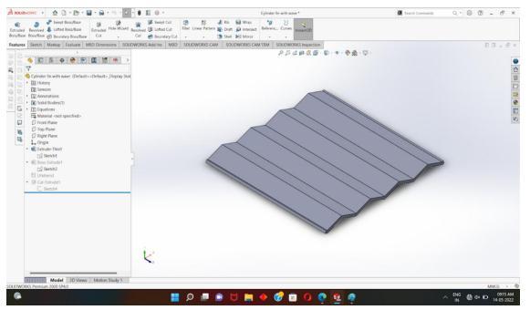
Step 2: Then converted it into 3D by using Extrude command,asshowninFig.4.7
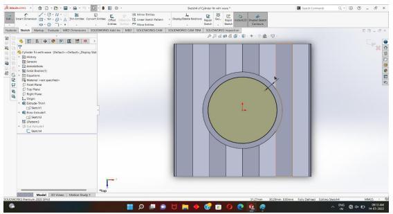
Fig. 4.9 : RemovetheInnerPartbyUsingCutandExtrude Command
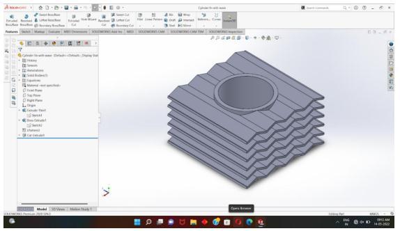
Step 4: DrawaWavyfinsovercylinderusingbossextrude, cutextrude&LPatternCommand,asshowninFig.4.10.
Fig. 4.7 : Converteditinto3DbyUsingExtrudeCommand
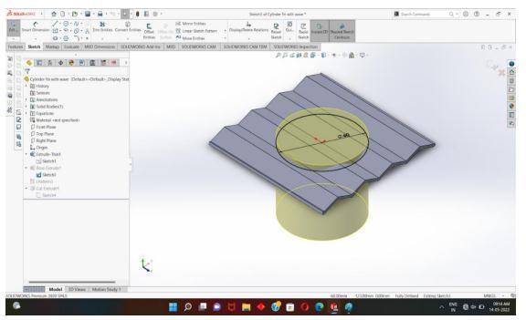
Step 3: Drawacirclewithradiusof30mmatthecenterand removetheinnerpartbyusingcutandextrudecommand,as showninFig.4.8&4.9.
Fig. 4.10 : DrawaWavyfinsovercylinder
Thus,usingabovestepsthecircular&wavyshapefinmodels arecreated.
The steady of thermal analysis determine the minimum temperature and heat flux as an object that does not vary with time. The surface temperature of engine cylinder is assumedto2000C.
1.Thetemperatureofairdoesnotchangesignificantly.
2.Constantheattransfercoefficientisconsideredforair.
3. Most material properties are constant such as thermal conductivity, elasticity modulus, coefficient of thermal expansionetc.
Fig. 4.8 ::Drawacircle
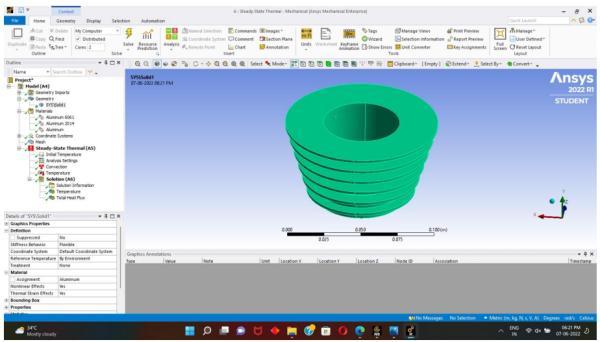
The geometry of fin created with SOLIDWORKS has to be savedin“.igs”fileformat.So,thatitcanaccessedthroughthe ANSYSsoftware.Theanalysisiscarriedoutforsteadystate heattransferprocess.Theimportedgeometryofcircularfin isshowninFig.5.1&ofwayfinisasshowninFig.5.2
Volume: 09 Issue: 06 | Jun 2022 www.irjet.net p ISSN: 2395 0072 © 2022, IRJET | Impact Factor value: 7.529 | ISO 9001:2008 Certified Journal | Page2647
International Research Journal of Engineering and Technology (IRJET) e ISSN: 2395 0056
Volume: 09 Issue: 06 | Jun 2022 www.irjet.net p ISSN: 2395 0072
1.Selectthemodelandgeneratethemeshforthedesign.


2. For meshing, program controlled mesh was used with adaptivesizingwithmediumsmoothing.
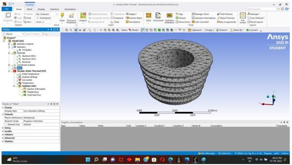
3. 11454 nodes and 5480 elements were generated in circular fins, and in case of wavy fins 25792 nodes and 12257elementsaregenerated.Themeshmodelofcircular finwith11454nodes&5480elementsisshowninFig.5.3& ofwavyfinwith25792nodes&12257elementsisshownin Fig.5.4
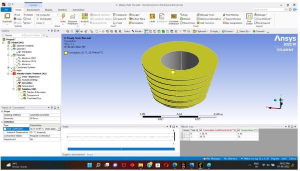
Aconvectionboundaryconditionisappliedtotheoutside surface of the cylinder and the fins with the ambient temperatureas35℃ ,andtheconvectioncoefficientas28.75 W/ (m2 ℃). The boundary conditions applied to outside surface of circular fin is shown in Fig.5.5 & of wavy fin is showninFig.5.6
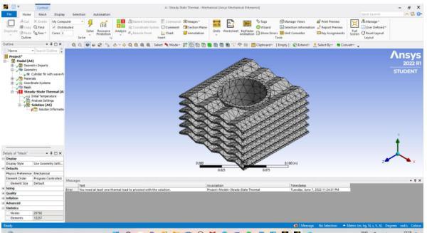
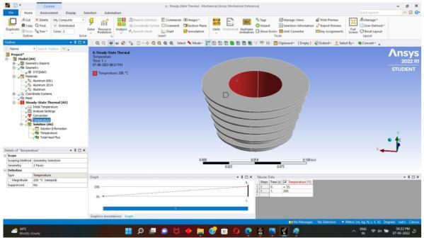
For loading conditions selecting the inner surface of the cylinder,assignthevalueoftheapproximatevalueofwall temperature 2000 C is applied. The Loading condition appliedoninnersurfaceofcircularfinisshowninFig.5.7& ofwavyfinisshowninFig.5.8
International Research Journal of Engineering and Technology (IRJET) e ISSN: 2395 0056
Volume: 09 Issue: 06 | Jun 2022 www.irjet.net p ISSN: 2395 0072
andminimumheatfluxisfoundtobe5.4116X105W/m2 & 10463W/m2respectivelyasshowninFig.6.12.
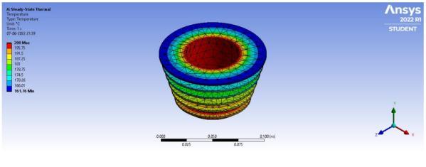
Fig. 6.1 : SteadyStateTemperatureofCircularFin (Aluminium)
Fig. 6.2 : SteadyStateTotalHeatFluxofCircularFin (Aluminium)

Followingresultsareobtainedfromthethermalanalysisof circularandwavyfinsusingANSYS.
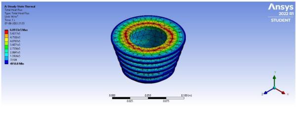
1.Thesteadystatetemperatureofaluminiumcircularfinis found to be 164.420CasshowninFig 6.1 &themaximum andminimumheatfluxisfoundtobe6.0933X105W/m2& 4950.8W/m2respectivelyasshowninFig6.2.
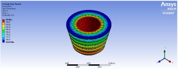
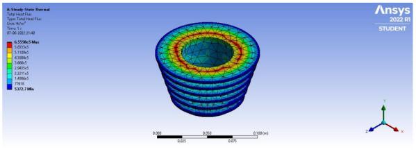
2.Thesteadystatetemperatureofaluminium6061circular fin is found to be 161.760C as shown in Fig.6.3 & the maximumandminimumheatfluxisfoundto be 6.5558 X 10⁵W/m2&5372.7W/m2respectivelyasshowninFig.6.4.
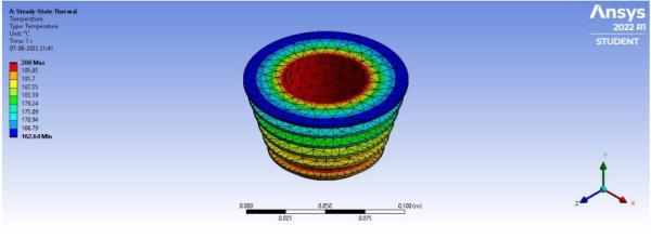
3.Thesteadystatetemperatureofaluminium2014circular fin is found to be 162.640C as shown in Fig.6.5 & the maximumandminimumheatfluxisfoundto be 6.4033 X 10⁵W/m2&5232.5W/m2respectivelyasshowninFig.6.6
4.Thesteadystatetemperatureofaluminiumwavyfin is foundtobe152.60CasshowninFig.6.7&themaximumand minimum heat flux is found to be 5.2051 X 10⁵ W/ m2 & 10050W/m2respectivelyasshowninFig.6.8.
5. The steady state temperature of aluminium wavy fin is found to be 149.020C as shown in Fig.6.9 & the maximum andminimumheatfluxisfoundtobe5.614X105W/m2& 10869W/m2respectivelyasshowninFig.6.10.
6. The steady state temperature of aluminium wavy fin is foundtobe150.020CasshowninFig.6.11&themaximum
Fig. 6.3 : SteadyStateTemperatureofCircularFin (Aluminium6061)
Fig. 6.4 : SteadyStateTotalHeatFluxofCircularFin (Aluminium6061)
Fig. 6.5 : SteadyStateTemperatureofCircularFin (Aluminium2014)
International Research Journal of Engineering and Technology (IRJET) e ISSN: 2395 0056
Volume: 09 Issue: 06 | Jun 2022 www.irjet.net p ISSN: 2395 0072
Fig. 6.6 : SteadyStateTotalHeatFluxofCircularFin (Aluminium6061)
Fig. 6.11 : SteadyStateTemperatureofWavyFin (Aluminium2014)
Fig. 6.7 : SteadyStateTemperatureofWavyFin (Aluminium)
Fig. 6.12 : SteadyStateTotalHeatFluxofWavyFin (Aluminium2014)
Table 6.1 : TemperatureandHeatFluxvaluesaccording toANSYS
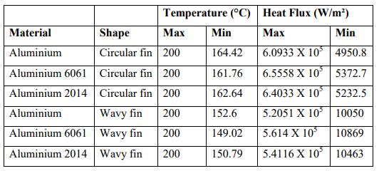
Fig. 6.8 : SteadyStateTotalHeatFluxofWavyFin (Aluminium)
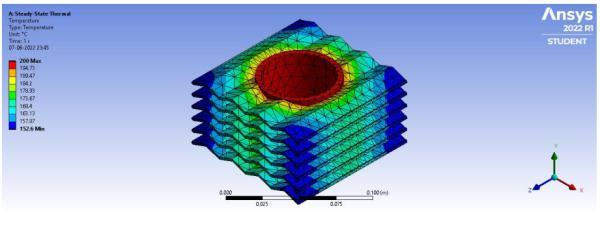
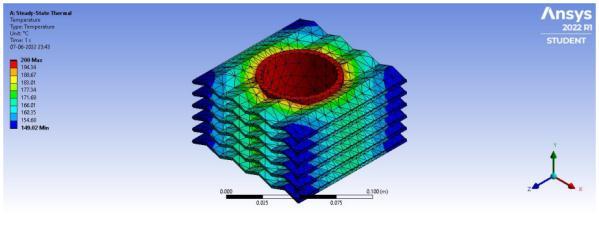
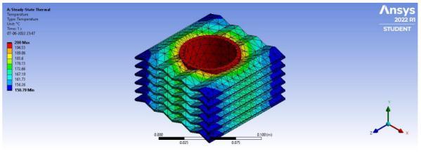
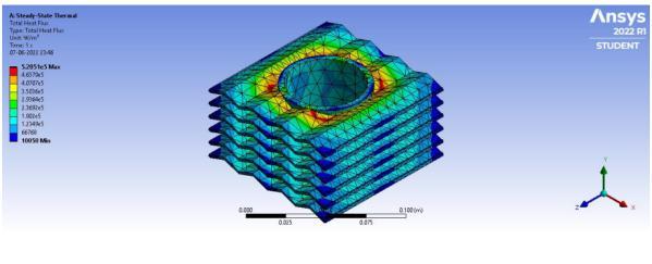
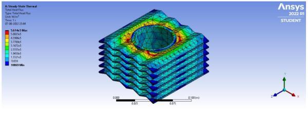
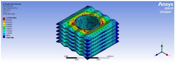
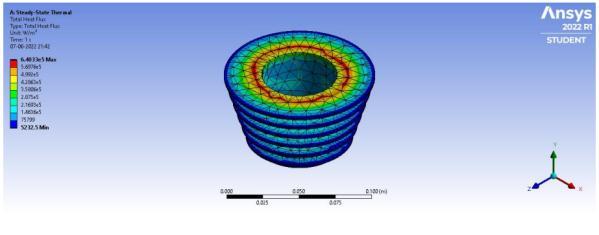
Fig. 6.9 : SteadyStateTemperatureofWavyFin (Aluminium6061)
Thus, from above tabulated results of thermal analysis of circular & wavy fins using ANSYS it is found that for aluminium6061wavyfinsgivesminimumtemperatureis 149.020C,thusmaximumheattransferisfeasibleforwavy finsascomparedtocircularfins.Fromabovediscussionis cleared that as compared to circular fin, the wavy fin improvesthecoolingrateoftheenginecylinderfin.
Fromthethermalanalysisofcylinderfin,itisconcludedthat wavy fins with aluminium 6061 is more effective as compared to other fins, for which the fin temperature is foundtobe149.020Canditsmaximum&minimumheatflux is 5.614 x 10⁵ W/m2 & 10869 W/m2 respectively. Thus, wavyshapefinscanreplacethecircularfins,soastoachieve effectiveheattransfer.
Fig. 6.10 : SteadyStateTotalHeatFluxofWavyFin (Aluminium6061)
[1] Biermann, Arnold E. & Pinkel, Benjamin. (1934) “Heat transfer from finned metal cylinders in an air stream”, UniversityofNorthTexasLibraries,UNTDigitalLibrary.
[2] Cramer, Robert, (1967) “Heat Rejection and Cooling RequirementsofInternalCombustionEngines”.No.670524. SAETechnicalPaper.
[3] Perlewitz, R. E., Lon Mooney, and Wm Kalweit, (1967) “Small Internal Combustion Engine Design Cooling and Associated Parameters, Heat Rejection Methods”. No. 670526.SAETechnicalPaper.
[4]Gale,NigelF.(1990)"Dieselenginecylinderheaddesign: the compromises and the techniques." SAE transactions: 415 438.
[5]Biermann,ArnoldE.,andHermanH.Ellerbrock(1941) “Thedesignoffinsforair cooledcylinders”.No.NACA TR 726.USGovernmentPrintingOffice.
[6] Zhang Yong, Zhang You, Chen Guohua and Zhang Baozhong (1998) “Structure Design and Finite Elements Analysis of LHR Cylinder Head for Vehicle Engines” No. 981487.SAETechnicalPaper.
[7] Memon, Zakirhusen K., T. Sundararajan, V. Lakshminarasimhan, Y. Babu, and Vinay Harne. (2005) "Parametric study on fin heat transfer for air cooled motorcycle engine." In International Mobility Engineering Congress & Exposition 2005 SAE India Technology for EmergingMarkets,No.2005 26 361.
[8]Yoshida,Masao,SoichiIshihara,YoshioMurakami,Kohei Nakashima, and Masago Yamamoto (2006) "Optimum Fin Layout of Air Cooled Engine Cylinder in Air Stream." SAE Transactions:1141 1149.
[9]Tripathi,PradeepMani,SatyaPrakash,RahulSingh,and SatishKumarDwivedi(2014)"ThermalAnalysisonCylinder Head of SI Engine Using FEM." International Journal of Scientific Engineering and Research (IJSER), ISSN: 2347 3878.
[10]Deshpande,A.C.,andMohdRazik(2015)."International Journal of Engineering Sciences & Research Technology DesignandFiniteElementAnalysisofTwoWheelerEngine Fins."ISSN:2277 9655
[11] Yellaji Bade (2017) “Thermal Analysis on Heat Distribution in Fins of Compressor Cylinder by Varying ProfileUsingFem.”ISSN:2348 4845.DesignandAnalysisof Cylinder Fins 2022 Mechanical Engineering Department BNCOEPusad.Page49
[12]N.Arul,G.Srinivasan,K.Sriram,M.Vignesh,S.Vijayaraj (2017) “Experimental and Computational Analysis of VariousTypesofFins”ISSN:2208 2727.
[13] K. Sathishkumar, K. Vignesh, N. Ugesh, P. B. Sanjeevaprasath, S. Balamurugan (2017) “Computational AnalysisofHeatTransferthroughFinswithDifferentTypes ofNotches”ISSN:2349 6495pp,2456 1908.
[14] Sorathiya A.S., Rathod P.P (2017) “Augmentation of HeatTransferCoefficientforVaryingFinsConfigurationof Cylinder Block of Si Engine” PHD thesis Department of MechanicalEngineeringRaiUniversity.
[15]Kumar,Rajat,DevendraSingh,andAjayKumarSharma (2020) "Static Thermal Analysis of Fins Models Using ANSYS."InternationalJournalofMechanicalEngineeringand Technology11,No.2.
[16]Shareef,SKMohammad,M.SaiVikas,ALNArunKumar, Abhishek Dasore, Sanjay Chhalotre, Upendra Rajak, and TrikendraNathVerma(2021)"Designandthermalanalysis of engine cylinder fin body using various fin profiles." MaterialsToday:Proceedings47,ISSN:5776 5780.
[17] Abbood, M. H., H. N. Azziz, and E. K. Farhoud (2021) "Investigating the effects of fin geometry on motorcycle cylinder cooling." In IOP Conference Series: Materials ScienceandEngineering,Vol.1067,No.1,pp.012102.IOP Publishing.
[18] R. K. Rajput, (2012), “Heat and Mass Transfer”, Fifth Addition,pp57to187.
International Research Journal of Engineering and Technology (IRJET) e ISSN: 2395 0056 Volume: 09 Issue: 06 | Jun 2022 www.irjet.net p ISSN: 2395 0072 © 2022, IRJET | Impact Factor value: 7.529 | ISO 9001:2008 Certified Journal |