International Research Journal of Engineering and Technology (IRJET) e-ISSN:2395-0056

Volume: 09 Issue: 06 | June 2022 www.irjet.net p-ISSN:2395-0072
International Research Journal of Engineering and Technology (IRJET) e-ISSN:2395-0056
Volume: 09 Issue: 06 | June 2022 www.irjet.net p-ISSN:2395-0072
1Rohit Maheshwari1
1Assistant Professor, Department of Civil Engineering, School of Engineering and Technology, DIT University, Dehradun, Uttarakhand, India ***
High risedesigngoalsincludestability,easeofmaintenance,durability,andaccommodationoftherequirementsinminimum space. Providing enough strength and stability against lateral stresses should be done precisely Optimal sizing which is of primeimportancefortheeconomyaccountsforoptimalstiffnessco relationshipsamongstructuralparts.High risestructural system is prone to the effects due to lateral loads, axial forces, shear forces, base shear, maximum story drift, and tensile forces In this paper, a comparative study is performed for G+20 Reinforced Concrete (RC) tie column and tie beam framed structures withand without the provisionofshear walls The analysisisperformed in the softwaretool E Tabs.Theapplied loadsandloadcombinationsarecalculatedandconsideredasperIndianCodal Provisions.Thestructure is consideredtobe locatedinseismiczoneIV. Theresultsofmaximumdriftvalues reveal thatthemaximumdrift decreaseswhena structureis configuredproperlywithashearwall.
Keywords: Shear Walls; RC Frame; Structural Response; Seismic Behavior; Maximum Drift
A building is subjected to a variety of forces, including lateral stresses induced by earthquakes, wind, and blasting Lateral loadscangenerateincreasedstrains,sidewaysmovement,andevenvibrations.Furthermore,theplananddesignofabuilding shouldbesturdyenoughtosustainverticalloads.Broadlyastructuralsystemcomprisesthefollowingconstituents:
1) System of Structural Frames: The structural system is a combination of frames, floor slabs, columns, and beams. These frameshavesufficientstiffnessandcanresistgravityloads.
2) Structural Wall Systems: Structuralwallsalsoknownasshearwallscontainallverticalmembersinthistypeofstructural system.
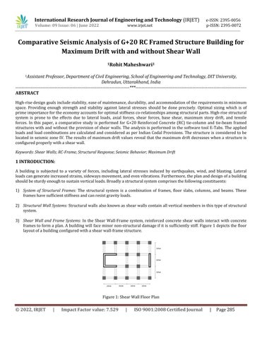
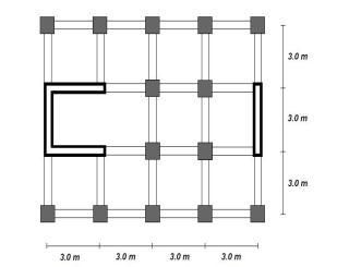
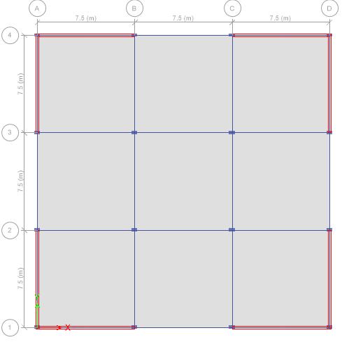
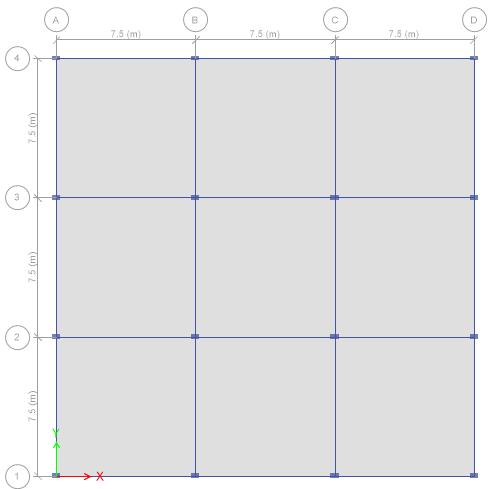
3) Shear Wall and Frame Systems: In the Shear Wall Frame system, reinforced concrete shear walls interact with concrete framestoformaplan.Abuildingwill faceminornon structuraldamageifitissufficientlystiff. Figure1depictsthefloor layoutofabuildingconfiguredwithashearwall framestructure.
Figure1:ShearWallFloorPlan
Volume: 09 Issue: 06 | June 2022 www.irjet.net p ISSN:2395 0072
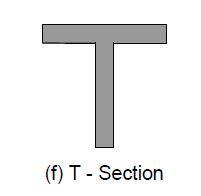
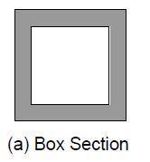
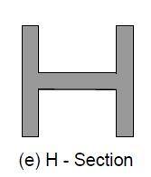
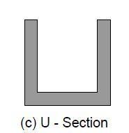
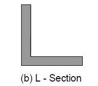
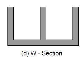
Modeling the structural system is an important step while analyzing lateral loads in building structures. Many models are developedsolelytodemonstratethebehaviorofashearwallstructure.Withthisaim,manyresearchershaveconductedtheir studies on wall frame structures and stated the shear walls to be more complicated than typical frame structures. Figure 2 showsthetypicalshearwallsections.
Inmulti storybuildings,theadaptionofshearwallshasbeenmandatorytoattainhigherresistanceagainstlateralloads. The importanceofdeterminingthemosteffective,efficientandoptimumsizeforshearwallscannotbeoversighted[1] Structures in high seismic zones may sustain significant damages. The most prevalent solutions for resisting lateral loads generated by earthquakes, wind, blasts, and other natural calamities are R.C. structures with ductile detailing and steel structures with bracings. E TABS is used in computer aided analysis to determine the most effective lateral load resisting system [2]. The seismic performance of a building frame can be improved by a well designed system of shear walls. The study takes into account various configurations of RC moment resistant framed building structures. According to the findings, symmetrically placedshearwallarrangementsthatformacorewillresultinimprovedstructuralperformance[3] IntheIndianconstruction scenario,high risespreadingprojectshavegrownextremelypopular.ManymajorIndiancitiesarelocatedinhigh riskseismic zones,necessitatingthereinforcementofbuildingstowithstandlateralstresses[4].PriyankaSonietal.performedstructural analysesonmultiplestorystructuresatvariouslocationsandheightsoftheshearwalls.Themulti storybuildingwasmodeled and analyzed while taking into account all gravitational and lateral loads (Wind Load and Earthquake Load) [5] They have Analyzed and designed a reinforced concrete rectangular shear wall to withstand the effects of an earthquake. Amar, et.al. usedSTAAD ProdesignsoftwaretodepicttheShearForceandLateralForceoperatingontheOfficeBuilding(G+5)inSeismic ZoneIV[6]
Tall buildings must be designed with strength, serviceability, stability, and human comfort in mind. The investigation is restrictedtomulti storyreinforcedconcretecommercialstructuresinfourseismiczones[7] Whenastructureisshakenbyan earthquake. The structure shakes in all three directions as a result of this motion [8] Due to dominant lateral loads, tall structures experience unusual loading effects and extremely high loading values. The stiffness co relation of structural elementsistakenintoaccountwhilesizing.Asa result,comparedtostandarddesignoptions,thereisacostsavings [9].Itis necessarytodeterminetheseismicreactionsofsuchstructurestodevelopearthquake resistantstructures.Amoresignificant methodology for structural seismic analysis is time history analysis. A dynamic analysis of a G+12 multistory practiced RCC building is performed, taking into account the earthquakes in Koyna and Bhuj [10]. Hence, the concept of structural engineeringaswellasthebasicunderstandingoftheoreticalandpracticalknowledgeofplanninganddesigningarerequired fortheanalysisanddesignofrobustanddurablemulti storybuildings[11].
The two most important components in a structure’s analysis and design are selecting an acceptable structural modeling method that depicts the system's actual behavior and deciding on the analyzing technique to be used for the structure. As
International Research Journal of Engineering and Technology (IRJET) e ISSN:2395 0056
Volume: 09 Issue: 06 | June 2022 www.irjet.net p ISSN:2395 0072
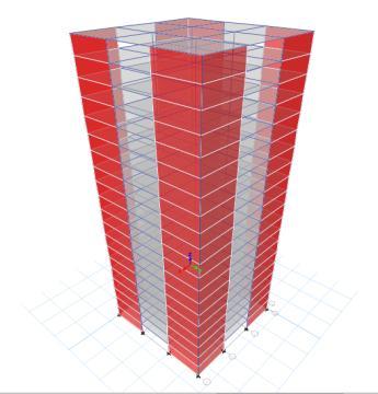
statedintheobjectiveofthestudy,twotypesofbuildingsareconsidered,i.e.,withandwithouttheprovisionofashearwallas shown in figure4. The modeling is performed in ETABS Software and demonstrates the 3 D view of the G+20 story RC plan buildingmodel.usingthefollowingtwobasicconcepts:
1) Analyses of the Maximum Story Drift: Inter storey drift is described as the ratio of lateral displacement of one floor of a multi story building concerning the floor just above or below and the height of a building. The drift is found to be maximuminthetopstoryofanybuildingstructure.Maximumdriftisdefinedastheratioofroofdisplacement(maximum displacement)tothetotalheightofabuilding.Table1depictstheadopteddatatomodelthebuildingstructure.
Table 1: StructuralDataofthedesignedmodel
Type of structure RC Framed G+ 20 Stories
Zone IV
ZoneFactor 0.24
ImportanceFactor 1 ResponseReductionFactor 5
Eachfloorheight 3meters
Thicknessofwall 200mm Thicknessofslab 200mm
WeightofFloorfinish 1.1kn/m2
Columnsize 750mmX750mm Beamsize 450mmX250mm
2) Model Design: Building model design contains designing the column, beam and slab elements; whose specifications are specified in Table 1. Two structural systems are considered to compare the behavior of a structure under the effect of lateral loads: structural systems without a shear wall (model 1) and structural systems with a shear wall (model 2) as elaborated in Figure 4. The results obtained through analyzing these structural systems are acquired in the form of maximumstorydrift
International Research Journal of Engineering and Technology (IRJET) e ISSN:2395 0056
Volume: 09 Issue: 06 | June 2022 www.irjet.net p ISSN:2395 0072
a) Model1 b)Model2
Figure 4:BuildingModel1withoutShearWall&Model2configuredwithShearWall
Note: The dimensions of beam, column, and slab elements for (Model 1 and Model 2) are considered similar to determine the effect of shear wall provision when the structure is applied with lateral loads. The applied loads and load combinations may vary in these two models according to Indian Codal Provisions.
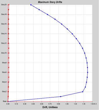

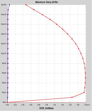
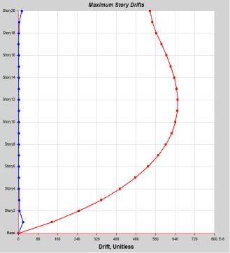
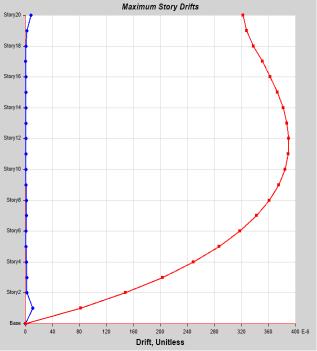
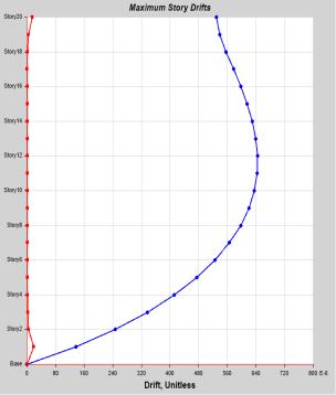
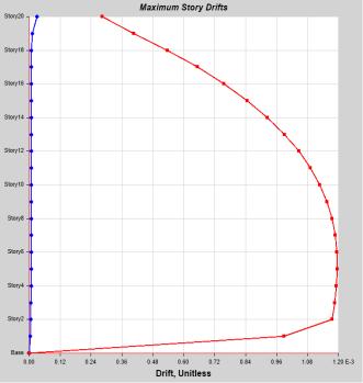
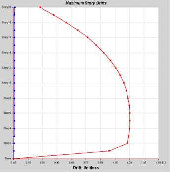
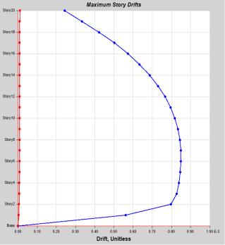
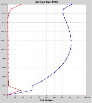
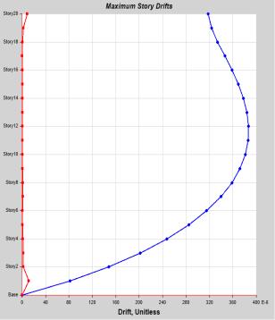
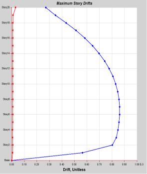
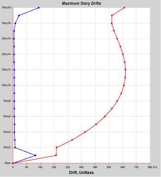
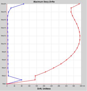
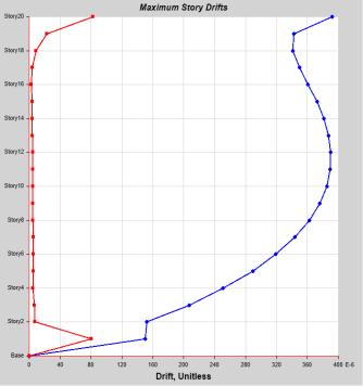
For a G+ 20 RC Framed structure located in Seismic Zone IV, a comparative study is performed adopting response spectrum analysisinSoftwaretool E tabs Multiplelocationsfortheprovisionofshearwallsareconsidered. AspertheIndianSeismic Provisions, a story drift in the structural system with partial safety factor 1 should not exceed 0.004 times the height of a structure. The obtained results of drift presented in Figures 5 8 indicates that the maximum value of drift is within the permissiblelimitofmaximumstorydrift. Figure5 6illustratesthe maximumstory driftinthex directionasdefinedby blue colorandthemaximumstorydriftinthey directionasdefinedbyredcolor.Figure7 8depictsthebuilding'smaximumdrift whenitisconfiguredwithshearwalls.
Figure 5: StoryDriftforLoadCombination1.5(DL+EQX+EQY)(Model 1)
International Research Journal of Engineering and Technology (IRJET) e ISSN:2395 0056
Volume: 09 Issue: 06 | June 2022 www.irjet.net p ISSN:2395 0072
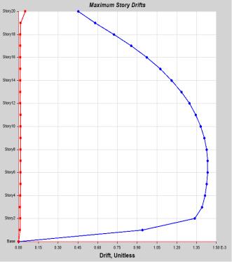
Figure 6: StoryDriftforLoadCombination0.9(DL+EQX+EQY)(Model 1)
Figure 7: StoryDriftforLoadCombination1.5(DL+EQX +EQY)(Model 2)
Figure 8: StoryDriftforLoadCombination0.9(D±EQX±EQY)(Model 2)
Figures 9 illustrate the maximum story drift for load combinations in the X direction for models 1 and 2, respectively, and Figure10showsthemaximumstorydriftintheY directionformodels1and2withaloadcombinationof1.5(DL+EQX +EQY) Similarly, Figures 11 illustrates the maximum story drift for load combinations in the X direction for models 1 and 2, respectively,andFigure 12 showsthe maximumstory drift inthe Y directionfor models1and2 witha load combination of 0.9(DL+EQX +EQY) Providing shear wall maximum drift value decrease by 12 15% in the x direction and 8 10% in the y direction
Note: Blue & grey line for M 1, orange and yellow line for M 2 for different load combination scenarios.
International Research Journal of Engineering and Technology (IRJET) e ISSN:2395 0056
Volume: 09 Issue: 06 | June 2022 www.irjet.net p ISSN:2395 0072
S to r y Dr i fy (m m )
0 0.0002 0.0004 0.0006 0.0008 0.001 0.0012 0.0014 0.0016
Maximum Story Drift for Load Combination 1 5( DL+EQx ) 0 0.0002 0.0004 0.0006 0.0008 0.001 0.0012 0.0014 0.0016
Sto ry 20 Sto ry 18 Sto ry 16 Sto ry 14 Sto ry 12 Sto ry 10 Sto ry 8 Sto ry 6 Sto ry 4 Sto ry 2 Bas e
No. of Stories
S to r y Dr i ft (m m )
Sto ry 20 Sto ry 18 Sto ry 16 Sto ry 14 Sto ry 12 Sto ry 10 Sto ry 8 Sto ry 6 Sto ry 4 Sto ry 2 Bas e
No. of Stories
Figure 9: MaximumStoryDriftforLoadCombination1.5(DL±EQX)Model1&2
Maximum Story Drift for Load Combination 1 5 (DL EQy )
0.002
0.0015
0.001
0.0025 Sto ry 20 Sto ry 18 Sto ry 16 Sto ry 14 Sto ry 12 Sto ry 10 Sto ry 8 Story 6 Story 4 Story 2 Bas e
S to r y Dr i ft No. of Stories
0.0005
0.0025
0.002
0.0015
Maximum Story Drift for Load Combination 1 5 (DL+ EQy ) 0
Maximum Story Drift for Load Combination 1 5 (DL EQx ) 0
0.001
0.0005
S to r y Dr i ft No. of Stories
Sto ry 20 Sto ry 18 Sto ry 16 Sto ry 14 Sto ry 12 Sto ry 10 Story 8 Sto ry 6 Sto ry 4 Sto ry 2 Bas e
Figure 10: MaximumStoryDriftforLoadCombination1.5(DL EQY)Model1&2
International Research Journal of Engineering and Technology (IRJET) e ISSN:2395 0056
Volume: 09 Issue: 06 | June 2022 www.irjet.net p ISSN:2395 0072
Maximum Story Drift for Load Combination 0 9 ( DL+EQx )
Story Drift (mm)
0 0.0002 0.0004 0.0006 0.0008 0.001
Story20 Story18 Story16 Story14 Story12 Story10 Story8 Story6 Story4 Story2 Base
No. of Stories
Story Drift (mm)
0 0.0002 0.0004 0.0006 0.0008 0.001
Story20 Story18 Story16 Story14 Story12 Story10 Story8 Story6 Story4 Story2 Base
No. of Stories
Figure 11: MaximumStoryDriftforLoadCombination0.9(DL EQX)Model1&2
Maximum Story Drift for Load Combiation 0 9 (DL+EQy ) 0 0.0002 0.0004 0.0006 0.0008 0.001 0.0012 0.0014
Maximum Story Drift for Load Combination 0 9 ( DL EQx ) 0 0.0002 0.0004 0.0006 0.0008 0.001 0.0012 0.0014
Maximum Story Drift for Load Combination 0 9 (DL EQy )
Story20 Story18 Story16 Story14 Story12 Story10 Story8 Story6 Story4 Story2 Base Stpry Drift (mm)
No. of Stories
Story20 Story18 Story16 Story14 Story12 Story10 Story8 Story6 Story4 Story2 Base Story Drift (mm)
No. of Stories
Figure 12: MaximumStoryDriftforLoadCombination0.9(DL EQY)Model1&2
FollowingsalientobservationsarederivedfromtheanalysisofG+20storyRCframebuildingwithandwithouttheprovision ofshearwalls:
1. The inclusion of a shear wall in an RC Frame Structure minimizes Story Drift, making it safer compared to an RC Frame Structurewithoutashearwall.Shearwallsinamulti storybuildingminimizetheStoryDrift.
2. The appropriate location of shear walls significantly reduces the structure's maximum drift. Summarily provision of properlydesignedshearwallsistheessentialneedforRCFramedstructuresinhigherearthquakezones.
1. SardarSJ,KaradiUN,SardarJ,KaradiN.EffectofChangeinShearWallLocationonStoreyDriftofMultistoreyBuilding SubjectedToLateralLoads. International Journal of Innovative Research in Science, Engineering and Technology (An ISO 2012; 3297(9):2319 8753.
© 2022, IRJET | Impact Factor value: 7.529 | ISO 9001:2008 Certified Journal | Page291
International Research Journal of Engineering and Technology (IRJET) e ISSN:2395 0056
Volume: 09 Issue: 06 | June 2022 www.irjet.net p ISSN:2395 0072
2. KevadkarMD,KodagPB.LateralLoadAnalysisofR.C.C.Building. International Journal of Modern Engineering Research (IJMER) 2013; 3(3):1428 1434.
3. KamalS,AzamM,HosurV.SeismicPerformanceEvaluationofMultistoriedRCframedbuildingswithShearwall2013; 4(1):2 7.
4. Dash SS. Seismic Analysis of High Rise Building by Response Spectrum Method National Institute of Technology Rourkela 20152015.
5. Soni MP, Purushottam Lal Tamrakar M, Kumhar V, Student PG. Structural Analysis of Multistory Building of Differentshear Walls Location and Heights. International Journal of Engineering Trends and Technology 2016; 32(1): 50 57.
6. Amar1 G, Gokul2 VS, Krishna3 KV, Rakesh4 D. Analysis and Design of Reinforced Concrete Rectangular Shear Wall 2016; 2(12):360 366.
7. Rakshith G M, Panendar naik G, Swarna D1, Chaithra R ADB. Analysis of G + 20 Rc Building in Different Zones Using Etabs. INTERNATIONAL JOURNAL OF PROFESSIONAL ENGINEERING STUDIES Volume 2017; VIII(3): 179 192. DOI: 10.15680/IJIRSET.2019.0805063.
8. Rakshith G M, Panendar naik G, Swarna D1, Chaithra R ADB. Analysis of G + 20 Rc Building in Different Zones Using Etabs. INTERNATIONAL JOURNAL OF PROFESSIONAL ENGINEERING STUDIES Volume 2017; VIII(3):179 192.
9. Yadav JC, Reddy LR. Dynamic Analysis of G + 20 Residential Building in Zone2 and Zone5 By Using Etabs. INTERNATIONAL JOURNAL OF PROFESSIONAL ENGINEERING STUDIES Volume 2017; VIII(3):333 346.
10. Kolekar AN, Pawar YP, Pise DCP, Mohite DD, Kadam SS. Comparative study of Performance of RCC Multi Storey BuildingforKoynaandBhujEarthquakes. International Journal of Engineering Research and Applications 2017; 07(05): 45 52.DOI:10.9790/9622 0705024552.
11. Siva CV, Prasad R. Analysis and Design of G + 20 Residential Rcc Building By Using Analysis and Design of G + 20 ResidentialRccBuildingByUsing2019(March).