International Research Journal of Engineering and Technology (IRJET) e ISSN:2395 0056

Volume: 09 Issue: 06 | June 2022 www.irjet.net p ISSN:2395 0072
International Research Journal of Engineering and Technology (IRJET) e ISSN:2395 0056
Volume: 09 Issue: 06 | June 2022 www.irjet.net p ISSN:2395 0072
Krisshiv Hinduja,1 Riya Kadulkar,1 Prof. Uttara Bhatt2
1 Student, Electronics and Telecommunication, Thadomal Shahani Engineering College, Maharashtra, India
2 Professor, Electronics and Telecommunication, Thadomal Shahani Engineering College, Maharashtra, India ***
Abstract In electronics, an adder is a digital logic circuit that is commonly used to add numbers. Adders are used in many computers and other types of processors to calculate addresses and associated actions, as well as table indices in the ALU and other portions of the processor. It is critical to select the appropriate adder for the task at hand. Because some adders provide higher speeds, lower power consumption, and superior performance, they must be chosen carefully and not at random.[1]. In this paper we are comparing 4 different adders on the basis of number of slices, speed, delay and power dissipation. This comparison will help to decide which adder to be used. The adders which we are going to compare are Ripple carry, Carry look ahead, Carry select, Kogge stone.
Key Words: Speed, Power Dissipation, Ripple Carry, Carry Look Ahead, Carry Select and Kogge Stone.
Addersareanimportantblockinalargenumberofdigitalsystemssuchasmicroprocessors,microcontrollersandvariousdata processingunits.Incertaincases,addersmayalsobeusedinpartsofaprocessor.Hereadditioncanbeexplainedasaprocess inwhichtwoinputquantitiesaretakenandaddedtogeneratetwooutputs,asumandacarry.
Themostimportantpartinanydigitalcircuitdesignistotryandincreasethespeedanddecreasethepowerconsumptionand area.The usageofadderscanreducethearea bya certainamount bydecreasingthenumber oftransistorsused.However,a single type ofadder cannot fulfilall ofthe criteria mentionedtherearedifferent kindsofaddersthatcan beuseddepending upontherequirementandtheproject.
Theaddersdiscussedinthepaperare: 1. CarryLookAheadAdder 2. CarrySelectAdder 3. RippleCarryAdder 4. KoggeStoneAdder
Eventhougheveryadderhasasimilarfunction,thewaythetaskbeingprocessedandthe transistorcountvaries.Everylogic stylehasitsownadvantagesanddisadvantagesthatinfluencethecriteriamentionedabove.Tomaketheselectionofanadder asimpletaskthecomparisonoftheabove mentionedaddershasbeendoneandputforward.
The paper is organized section wise. Section II describes the working and the circuit of the adders mentioned. Section III explains the Simulation results. Section IV focuses on the comparison of the adders mentioned and the conclusion of the comparisonhasbeenputintoSectionV.
•
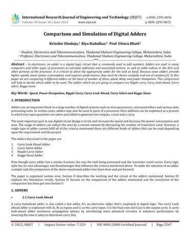
A carry lookahead adder is also called a fast adder. It's an electronic adder that's employed in digital logic. The carry Look AheadadderisexplainedwithAi,BiasinputsandCiasthecarryinput. SisthefinalsumandCoutistheoutputcarry.Acarry look ahead adder minimizes propagation latency by introducing more advanced circuitry. It enhances performance by loweringthetimeittakestodeterminecarrybits.
International Research Journal of Engineering and Technology (IRJET) e ISSN:2395 0056
Volume: 09 Issue: 06 | June 2022 www.irjet.net p ISSN:2395 0072
Fig 1: CarryLookAheadAdder
A B Ci Ci+1 Condition 0 0 0 0 NoCarryGenerate 0 0 1 0 0 1 0 0 0 1 1 1 NoCarryPropogate 1 0 0 0 1 0 1 1 1 1 0 1 Carry Generate 1 1 1 1
Consider the wholeadder circuitwiththeaccompanyingtruth tablegiven above. Thevariables'carry generate' Piand'carry propagate'Giarethendefined.
Pi=Ai�Bi Gi=AiBi Carrygenerateandcarrypropagatecanbeusedtoexpressthetotaloutputandcarryoutput. Si=PiCi
Ci+1 =Gi+PiCi whereGiproducesthecarrywhenbothAi,Biare1regardlessoftheinputcarry.Piisassociatedwiththepropagationofcarry fromCitoCi+1.
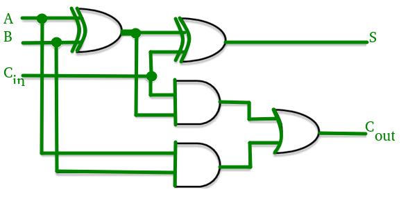
Inafour stagecarrylook aheadadder,thecarryoutputBooleanfunctionofeachstagecanberepresentedas
C1=G0+P0Cin
C2=G1+P1C1=G1+P1G0+P1P0Cin
C3=G2+P2C2=G2+P2G1+P2P1G0+P2P1P0Cin
C4=G3+P3C3=G3+P3G2+P3P2G2+P3P2P1G0P3P2P1P0Cin
International Research Journal of Engineering and Technology (IRJET) e ISSN:2395 0056
Volume: 09 Issue: 06 | June 2022 www.irjet.net p ISSN:2395 0072
FromtheaboveBooleanequations,wecanobservethatc4doesnothavetowaitforc3andc2to propagatebutactuallyc4is propagatedatthesametimeasc3andc2.SincetheBooleanexpressionforeachcarryoutputisthesumofproductssothese canbeimplementedwithonelevelofANDgatesfollowedbyanORgate.
The implementation of three Boolean functions for each carry output (c4, c3 and c2) for a carry look ahead carry generator showninbelowfigure.
TimeComplexityAnalysis:
Acarrylook aheadaddercanbethoughtofashavingtwoparts
• Thissectioncalculatesthecarryforeachbit.
• Foreachbitposition,thisisthecomponentthataddstheinputbitsandthecarry.
Thelog(n)complexityarisesfromthepartthatgeneratesthecarry,notthecircuitthataddsthebits.Now,forthegenerationof the nth carry bit, we need to perform a AND between (n+1) inputs. The complexity of the adder comes down to how we performthisANDoperation.IfwehaveANDgates,each witha fan in(numberofinputsaccepted)of k,thenwecanfindthe ANDofallthebitsinlogk(n+1)time.Thisisrepresentedinasymptoticnotationas⊖(logn).
AdvantagesandDisadvantagesofCarryLook AheadAdder: Advantages
• Thepropagationdelayisreduced.
• Itgivesthequickestadditionlogic.
• Asthenumberofvariablesgrows,theCarryLook aheadaddercircuitbecomesmoredifficult.
• Thecircuitismoreexpensivesinceitusesmorehardware.
International Research Journal of Engineering and Technology (IRJET) e ISSN:2395 0056
Volume: 09 Issue: 06 | June 2022 www.irjet.net p ISSN:2395 0072
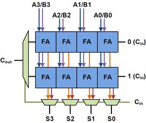
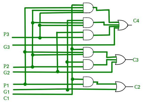
The basic building block of a carry select adder is shown above, with a block size of 4. Two 4 bit ripple carry adders are multiplexed together, with thecarry in selecting the resultantcarry and sum bits. Because one ripple carry adder assumes a carry in of 0 while the other assumes a carry in of 1, using the actual carry in to determine which adder had the proper assumptionproducesthedesiredresult.
Similarly,avariable size16 bitcarry selectaddercanbecreated.Anadderwithblocksizesof2 2 3 4 5isshownbelow.When the full adder delay equals the MUX delay, which is unusual, this break up is excellent. Two complete adder delays and four muxdelaysmakeupthetotaldelay.Westrivetokeepthedelaybetweenthetwocarrychainsandtheprecedingstage’scarry chainequal.
• Itisfaster.
• Itrequiresalargerarea.
International Research Journal of Engineering and Technology (IRJET) e ISSN:2395 0056
Volume: 09 Issue: 06 | June 2022 www.irjet.net p ISSN:2395 0072
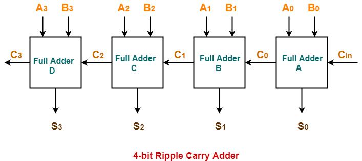
Aripplecarryadderisalogiccircuitthatismadeupof multiplefulladdersarrangedinacascadeform.Inthiseachcarrybit getsrippledintothenextstage.Thecarryoutbitofthefulladderbecomestheinputcarrybitforthenextfulladder.Thereare threetypesofripplecarryadders 4 bit,8 bitand16 bit.Thecircuitforthe4 bitripplecarryadderisshowninFigurebelow.
The ripple carry adder has a high propagation delay, the time that occurs between the input and output. This propagation delay affects the speed of the circuit and also the power consumption. The circuit has low area consumption but high delay time,slowinspeedandalsohighpowerconsumption.Theequationsfortheripplecarryadderareshownbelow.
Sum=A1⊕B1⊕Cin
Carry=A1B1⊕B1Cin⊕CinA1
The inputsusedforthe full adder are Aand Bandafter addition we getthe SumandCarry. When the inputsAoandBoare given tothefirstfull adder alongwiththestartingcarryCinas0thesumandcarryareobtained usingtheabove mentioned equations.ThecarrywillberippledtothenextfulladderandtheinputbitsA1andB1aregivenalongwiththerippledcarry. Thisprocessgoesonuntilthefinalfulladderwhichprovidesuswiththeoutputsumandcarrybits
Theripplecarryadderisusedwhentheinputbitsarelargeandtheoperationcannotbeperformedbythefulladdersandhalf adders.Theadvantageobtainedhereisthatadditionforn bitsequencescanbeperformedbutatthecostofthespeedofthe circuitasthedelaytimeishigh.
TheKoggeStoneadderisanexampleofaparallelprefixadder.Itisflexibleascomparedtotheotheraddersandalsoperforms the operations with high speed. It is considered as a high performance adder due to minimum logic depth which in turns increasesthespeed.Thecircuitdiagramforthe4 bitkoggestoneadderisshowninFigure.
International Research Journal of Engineering and Technology (IRJET) e ISSN:2395 0056
Volume: 09 Issue: 06 | June 2022 www.irjet.net p ISSN:2395 0072
Thisadderisthemosthighlyusedadderinindustriesthatrequirehighspeedperformanceandas32 bit,64 bitand128 bit adders.Thekoggestoneadderreducesthedelaytimebyalargeamounttoobtainthecarrysignals.Thedelayisrepresented by the equation log2n which is the number of stages present in the operator. The equations for the kogge stone adder are shownbelow.
Pi:j=Pi:k+1ANDPk:j
Gi:j=Gi:k+1OR(Pi:k+1ANDGk:j)
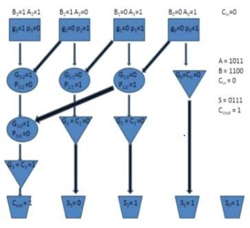
The circuit is made up of three stages. The first stage makes use of full adders provided with the input carry to obtain the propagate (P) and generate (G). The second stage uses the above equations to generate the bits P1 and G1. The third stage similarly generates the term P2 and G2. The sum bits are generated depending on the output of the first stage and the generatedterms.
Inthissectionwe’llbediscussingsimulationoftheadders.TheXilinxsynthesistoolisusedforsynthesisandXilinxsimulation toolisusedforsimulation.Thesimulationresultsprovideuswithdataontheoperands,operation,andoutcomes.[1]
TheoperandsusedhereareAandBthatinclude4bitsalongwithaninputcarryCin.Thevaluesofoperandstaken:
ForcarrylookaheadadderareA=“0110”,B=“0100”,cin=0whichresultsinthesumasS=“1010”andoutputcarryascout= ‘0’.
Fig 7: SimulatedWaveformofCLA
International Research Journal of Engineering and Technology (IRJET) e ISSN:2395 0056
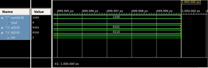
ForcarryselectadderareA=“0101”,B=“0110”,cin=1whichresultsinthesumasS=“1100” andoutputcarryascout=‘0’.
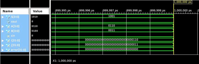
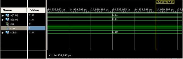
ForripplecarryadderareA=“1111”,B=“1111”,cin=0whichresultsinthesumasS=“1110” andoutputcarryascout=‘1’.
ForKoggestoneadderareA=“1101”,B=“1100”,cin=0whichresultsinthesumasS=“1001” andoutputcarryascout=‘1’.

Fromthestudywecananalyzetheareaoccupiedandthespeedoftheoperationfor eachadderusingtheXilinxsoftwareand correspondingVHDLandVerilogCodes.Thisgivesabriefideaabouttheadderselectionandshowsthatoutofthefouradders mentionedtheKoggeStoneAdderisthemostefficient.[3]
TheAdderscanalsobecomparedbasedonthenumberofgatesusedwhichinturnagaincompensateforthearea.TheKogge stoneadder makesuseof thegreatestnumberof gates. ThencomestheCarry SelectAdder with a gatecountof around600.
Volume: 09 Issue: 06 | June 2022 www.irjet.net p ISSN:2395 0072 © 2022, IRJET | Impact Factor value: 7.529 | ISO 9001:2008 Certified Journal | Page2553
Fig 8: SimulatedWaveformofCSA Fig 9: SimulatedWaveformofRCA Fig 10: SimulatedWaveformofKSAInternational Research Journal of Engineering and Technology (IRJET) e ISSN:2395 0056
Volume: 09 Issue: 06 | June 2022 www.irjet.net p ISSN:2395 0072
The Carry Look Ahead Adder has the least number of gates that is 272 and the Ripple Carry Adder has the gate count approximatelyequalto288.
SR.NO AdderTopology Area / NoofSlices Speed (ns) LUTUsed
1. RippleCarry 4 8.96 9
2. CarryLookAhead 4 8.92 11
3. CarrySelect 5 8.35 9
4. KoggeStone 4 7.82 5
Table 2: ComparisonbasedofAreaandSpeed
The Adders mentioned can also be compared using a few different parameters such as the power dissipation and the delay timethattakesplaceinaparticularoperation.Thetable belowprovidesacomparisonfortheparametersmentionedandone canaccordinglyselectanAdderthatbestsuitsthepurposeortheoperationtobeexecuted.
SR.NO AdderTopology Delay(ns) PowerDissipation
1. RippleCarry 6.445 0.206mW
2. CarryLookAhead 13.463 1.082mW
3. CarrySelect 12.425 1.109mW
4. KoggeStone 9.077 3.022mW
Table-3: ComparisonbasedonPowerDissipationandDelay
Forthecomparative study, theabove mentioned differentaddershave been compared using the VHDL or VerilogCodes. The comparisonbasedonthedifferentparametershavebeenmentionedinthetableshownbelow.TheKoggeStoneAdderproves to be one of the best among all the adders that are mentioned. The Ripple Carry Adder consumes less area but takes a comparativelylargertimeforexecution.TheCarryLookAheadAdderrequiresalmostthesameareaasthatoftheRippleCarry Adder but compared to the Ripple Carry Adder it executes the operation in a lesser time as compared to it. The Carry Select AdderhasalesserspeedascomparedtotheCLAAdderbuttheareaoccupiedbyitislargerthantheotheradders.TheKogge StoneAdderhasthesamearea astheRippleCarryand CarryLookAheadbutthespeedof operation isthefastestamongall theadders.ThemostefficientperformanceamongalltheadderscanbeobtainedusingtheKoggeStoneAdder.[3]
1. Bhavani Koyada,N.Meghana,Md. Omair Jaleel and Praneet Raj Jeripotula,“AComparative Study On Adders,” in IEEE WiSPNET2017conference.
2. R.UMA,Vidya Vijayan , M. Mohanapriya ,Sharon Paul, “Area, Delay And Power Comparison Of Adder Topologies,” in InternationalJournalofVLSIdesign&CommunicationSystems(VLSICS)Vol.3,No.1,February2012.
3. R. Jacob Baker, CMOS Circuit Design, Layout and Simulation, IEEE Press Series on Microelectronic Systems Stuart K. TewksburyandJoeE.Brewer,SeriesEditors,WileyStudentEdition
4. M.MorrisMano,DigitalLogicandComputerDesign,ThirdEdition.