International Research Journal of Engineering and Technology (IRJET) e ISSN:2395 0056

Volume: 09 Issue: 06 | June 2022 www.irjet.net p ISSN:2395 0072
International Research Journal of Engineering and Technology (IRJET) e ISSN:2395 0056
Volume: 09 Issue: 06 | June 2022 www.irjet.net p ISSN:2395 0072
Professor, Chaitanya Bharathi Institute of Technology, Hyderabad, India1, Assistant Professor, Chaitanya Bharathi Institute of Technology, Hyderabad, India2,3 UG Student, Chaitanya Bharathi Institute of Technology, Hyderabad, India4,5,6 ***
Abstract:
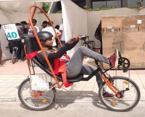
The objective is work is to design and fabricate a Human Powered Vehicle (HPV) that is efficient, lightweight and comfortable for long range cycling distances. To achieve the stated objective, a semi recumbent configuration is used, which ensures simple structure and comfort to the rider. A roll over protection system (RPS) is added to this type of configuration which can assure stability and safety of the rider in case of a fall. Initial design has been made taking into considerations the average anthropometric measurements of riders available. Wide range of analyses has been done on the frame to ensure the design is both safe and light in weight. Physical testing has been carried out to ensure that the desired vehicle performance is met, while simultaneously satisfying all other safety requirements
Key words:HumanPoweredVehicle(HPV),Rolloverprotectionsystem(RPS),FiniteElementMethod(FEM)
Human Powered Vehicle is used to refer all the vehicles that run on muscular power of a human. A real HPV can be poweredbyanelectricengine,buttheenergymustcomefromahumanpoweredgenerator.Electricbicycleswithbatteries onboarddonotincludetoHPVs.HPVscanbefoundinrail,waterandalsoroad.BicyclesformthelargestsectionofHPVs. As theincreasing needsofa manisleadingtofasterchange inclimate,HPVshavea greaterscopeofbeing employedfor commutingforrelativelylongerdistancesincities.TheobjectiveofthisworkistodevelopaHPVthatcantakeslesseffort to ride with the safety to the rider and provides back support for easier riding of long distances in cities. A recumbent bicycle is a bicycle that places the rider in a laid back reclining position. Most recumbent riders choose this typeofdesignforergonomicreasons Therider'sweightisdistributedcomfortablyoveralargerarea,supportedbyback and buttocks. On a traditional upright bicycle, the body weight rests entirely on a small portion of the sitting bones, the feet,andthehands.
In the event of an accident, all vehicles must include a rollover protection system that protects all drivers in the vehicle. TheRPSmustAbsorbsufficientenergyinasevereaccidenttominimizeriskofinjuryandPreventsignificantbodycontact with the ground in the event of a fall (vehicle resting on its side) or rollover (vehicle inverted). It also Provide adequate abrasionresistancetoprotectagainstslidingacrosstheground.Thisisparticularlyimportantaroundtherider’sarmsand legs. Adequate guarding must be included. The RPS must allow for a load path supporting the driver and retaining them frombeingejectedfromtheHPVintheeventofacrash. Thisloadpathwillbedefinedfromtheground(impactpoint),to the outside of the vehicle body, through the structural RPS, through the safety harness, to the driver’s body (center of gravity).A thorough RPS design includes the structural fortitude of not only the roll bar/frame, but also a rigidly mounted and structurally sound seat and properlyaffixedsafetyharness.
RPSLoadCases:TheRPSsystemshall beevaluatedbasedontwospecific loadcases, a toploadrepresentinganaccident involvinganinvertedvehicleanda sideloadrepresentinga vehiclefallenonitsside.Inthesetwocasestheappliedload shall be reacted by constraints at the seat belt attachment points; simulating the reaction force exerted by the rider in a crash.
The vehicle must demonstrate that it can come to a stop from a speed of 25 km/h in a distance of 6 m and can turn within an 8.0m radius. It also should demonstrate stability by traveling for 30 m in a straight line at aspeed of 5 to 8 km/h(fastpacedwalkingspeed).
International Research Journal of Engineering and Technology (IRJET) e ISSN:2395 0056
www.irjet.net
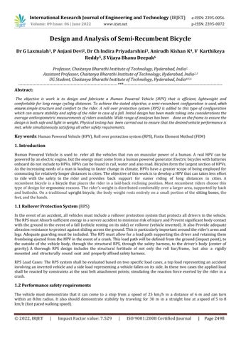
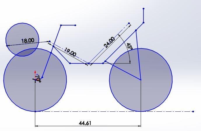
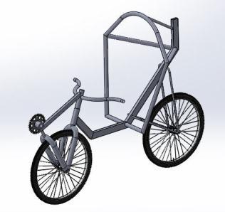
Front View of the Vehicle Side view of the Vehicle Isometric View
Figure1:RPS
towithstandSideandTopLoad
It is evident that cycling performance would appear to be dictated largely by the ability of the cyclist to produce high poweroutputsatminimalmetaboliccosts.Aspedalrate(i.e.cadence)caninfluenceboththeabilitytoproducepower,as well as rate of energy consumption, cadence selection could have a significant impact on cycling performance. While informationconcerningpedalrateselectionduringcyclingexists,acomprehensivereviewofthepresentliteratureisnot currently available. As such, the cadence that results in the best possible performance outcome during the vast array of cycling events and conditions remains unclear. An elucidate knowledge about cadence abets the selection of efficient drivetrainconfiguration[1].FactorsaffectingthecadenceareMuscularFactors,NonmuscularfactorsandAerodynamics
After market research and study of different materials, it narrowed down to thethree suitable materials for the purpose,thoseare Aluminium 6061, AISI 1018 Steel, AISI 4130 Steel.AISI4130gradesteelisusedforthefabricationof thevehiclebecauseitisaversatilealloywithgoodatmosphericcorrosionresistance,strength,toughness,weldabilityand machinability
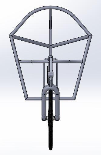
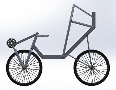
The frame is designed for two wheeled front wheel drive, semi recumbent human powered vehicle which has a short wheelbase. The base frame was manufactured using rectangular tubes of AISI 4130 Material, based on design iterations the frame cross section was decided as shown in the figure 2. The frame geometry has been decided based on anthropometricdataandthisgeometryisdesignedtoaccommodateeveryriderwithcomfort.
Figure2:Ergonomicallydesignedmodelforfabrication
International Research Journal of Engineering and Technology (IRJET) e ISSN:2395 0056
Volume: 09 Issue: 06 | June 2022 www.irjet.net p ISSN:2395 0072
TheRPSplaysaveryimportantroleinrider’ssafety.TheRPSwasdesignedaccordingtoHPVCRulebook.AISI4130pipes ofcircularcrosssectionisusedtoconstructtheRollbar.
ThedrivetrainoftheHPVisFrontWheeldrivewithmovablebracketsystem.FWDhasbeenchosenoverRWDasthereare several power lossesinRWD recumbentasthepower istransferred fromfronttorear wheel throughseveral additional pulleys. The FWD with moving bracket helps the chain not to misalign during propulsion. The powertrain consists of 7 speedcassettessoastoofferflexibilitytothedriverfordifferentscenarios.
HPVisequippedwith24”tyreonthefrontand24”ontherear. ThoughthevehicleisFrontwheeldriven,a24”wheelhas beenusedtoavoidinterferencebetweensprocketandwheel.
TheframeismodeledinSolidworkssoftwareandthismodelisimportedtoANSYSanalysissoftware
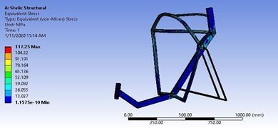
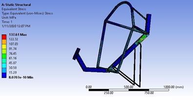
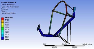
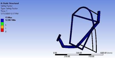
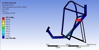
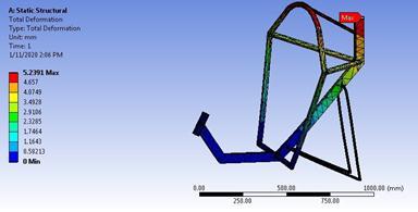
4.1 Top Load Analysis: in this analysis a load [3] of 2670N applied to the top of the roll bar directed downwards towardstorearofthevehicleatanangleof12degreesfromthe vertical,thereactantforceisappliedtoseatbelt,seator rollbarattachmentpoint.TheVonmisesstressinduced,totaldeformationandfactorofsafetywereidentified
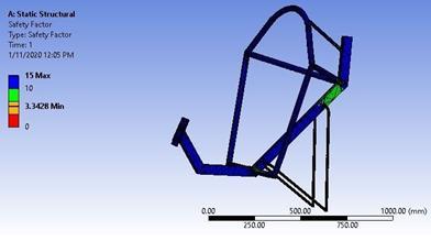
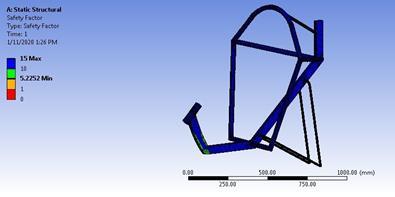
4.2 Side Load Analysis:TheRPSisprovidedtoprotecttheriderfromgettingincontactwiththegroundatthe time of collision or imbalance. A side load of 1330N shall be applied horizontally to the side of the roll bar at shoulder height. The reactant forcewasappliedtoseatbelt,seatorrollbarattachment.Themaximumdeformation,Vonmises stressandFactorofsafetyarecalculated.Boththetoploadandsideloadresultsaretabulatedinthetable1
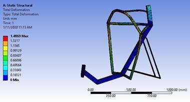
Table1:ResultforRPSanalysis
Case Maximumelastic deformation(mm) MaximumVonmises stress(MPa) FactorofSafety
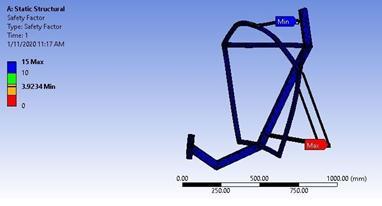
Topload 1.486 117.25MPa 3.92 Sideload 4.959 137.61MPa 3.34
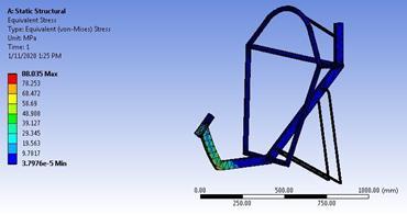
Figure3: Top load induced Vonmises Stress
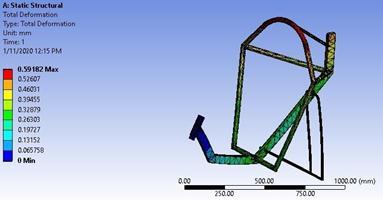
Figure4: Top load Total Deformation
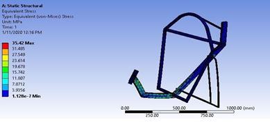
4.3 Static Analysis: The rider is assumed to be sit on seat member and the behavior of the frame under the rider’s weight is analyzedstatically The maximum rider weight is assumed tobe800N.Theloadisappliedonseatmemberand fixedsupportconstraintswereappliedatheadtubeandreardropout.
Inthiscase,thebehaviorofframeissimulatedwhenthevehicleencountersabump.Thefrontforkandhandleassembly takes the shock and it is transferred to the head tube in the frame. A remote force of 1300N representing the impact is applied at the point at which the wheel axle is supposed to be present. The equivalent stress, maximum deformation & factorofsafetyarecalculated.
Thiscasesimulates theloadingonframeduringthebraking ofvehicle. The averagespeedofvehicleisconsideredand target speed for stopping is fixed and the braking force required is calculated and this force is transmitted through the axle. The seat member is fixed and remote force is applied representing the frontwheel braking force and rear wheel brakingisbeingtransmittedtotheframethroughfork.Ithasbeenobservedthatstressinducediswithinthelimits
Theresultsobtainedfromstaticanalysis,bumpanalysisandbrakeforceanalysisaretabulatedinthetable2
ForceappliedatthebrakeF1=65N,Brakingfactortaken=5
ForcegeneratedatthecaliperF2=65x5=325N
Torqueproducedbythebrakingsystem
Tb=2xµxF2xre (1)
International Research Journal of Engineering and Technology (IRJET) e ISSN:2395 0056
=2x0.75x325x0.25=121.88 N m (Consideringthetwobrakepadsincontact)
µ=coefficientoffrictionbetweenbrakepadandrim
re=effectiveradiusoftyre
Torqueproducedatthewheel Tw=FxR (2) R=radiusofthewheelinm
Forsuccessfulapplicationofbrakes Tb >Tw
Tb=Tw (3)
Forreartyre Rr =0.304m(Rearwheeldiameter=24inches) 121.88= Fr x0.304
Frictionalforceactingonthereartyre Fr=400.92N
Forfronttyre Rf =0.304m(Frontwheeldiameter=24inches) 121.88= Ff x0.304
Frictionalforceactingonthefronttyre Ff =400.92NMass m =100kg
acceleration= a m/s2 ∑F=mxa (4) 400.92+400.92=100x a a=8.01m/s2
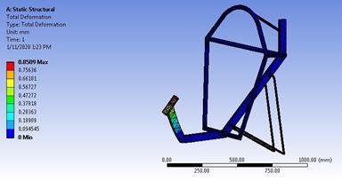
StoppingDistance (S):Let u=25km/hr=6.94m/s v2 u2 =2xaxS (5) 0 (6.94)2=2x( 8.01)x S, S=3.00m.Thestoppingdistanceisfoundtobe 3m. Figure9: Static Induced Vonmises Stress Figure10: static Total Deformation
Volume: 09 Issue: 06 | June 2022 www.irjet.net p ISSN:2395 0072 © 2022, IRJET | Impact Factor value: 7.529 | ISO 9001:2008 Certified Journal |
International Research Journal of Engineering and Technology (IRJET) e ISSN:2395 0056
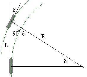
Calculationofsteerangle: Theturningradiuscanbedeterminedbytherelation sin(δ)=L/R (6)
Where L=Wheelbaseofthevehicle(m) R=Radiusofturning=8m δ =anglethroughwhichwheelturnsThevehiclehasawheelbaseof 1.13m MinimumradiusofturningaccordingHPVCrulebook2020is 8mThemaximumvalueofsin(δ)= L/R =1.13/8 =0.1412 δ =sin 1(0.1412)=8.12o
Thereforeminimumsteerangleis 8.12o
Thechainringandcogspecificationsarechosenbasedonrequirementforbothdragandenduranceevents
Table 3: Cadences for different events
Event Optimum Cadence(rpm) DragRace 120 Endurance 90 Ultra Endurance 70
Thespeedsforthechosencadenceandgearratiosaretabulatedinthetable4.
Table 4: Drivetrain Analysis
Chainring Cog Distance travelled in 1rotation of the crank (inches)
Gearratio 50 12 314 33.50 43.06 57.42 4.166 50 14 270 28.80 37.00 50.00 3.571 50 16 236 25.17 32.36 43.16 3.125 50 18 209 22.30 28.65 38.19 2.777 50 21 180 19.20 24.70 33.00 2.381 50 24 157 16.75 21.55 28.72 2.083 50 28 135 14.40 18.50 24.70 1.785 50 32 118 12.58 16.18 21.58 1.562
Speed at70rpm Cadence(Kmph) Speed at90rpm Cadence(Kmph) Speed at 120rpm Cadence(Kmph)
This section contains various static and dynamic tests conductedon thevehicletocheckitsperformance,reliabilityand functioning.
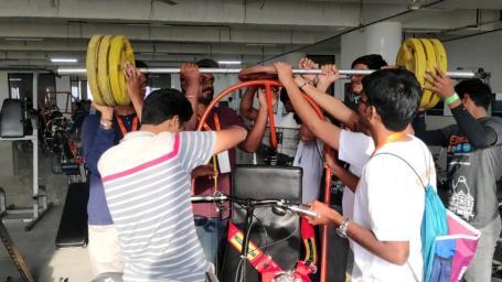
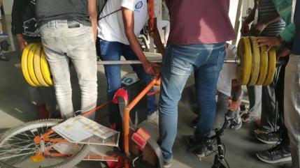
Top Load Testing: Inthegymnasium,weightliftingrodwasinitiallyplacedonthetopmemberoftheRPSand weightsof magnitude 27kg were added on the either side of the rod. Deflections were noted with weights and after removing the weights.Thenetdeflectionobtainedas7.62mm
Side Load Testing: InthegymnasiumthedeadweightsaretoapplyaloadonsidememberofRPS.Weightliftingrodwas initiallyplacedonthesidememberoftheRPSandweightsofmagnitude27kgwereaddedanddeflectionswerenotedwith weightsandafterremovingtheweights.Thenetdeflectionobtainedas5.08mm
Volume: 09 Issue: 06 | June 2022 www.irjet.net p ISSN:2395 0072 © 2022, IRJET | Impact Factor value: 7.529 | ISO 9001:2008 Certified Journal
Figure18:ToploadandSideLoadTesting
The following conclusions can be drawn from the interpretation of the results of the HPV obtained from the analysis, testing
It has been observed that there isn’t a considerable deviation in the results obtained from analysis and testing. Thetotalweightofthevehicleis24kg.
● Therollbarcouldwithstandtheweightswithminimumdeformation
● Stoppingdistanceofthevehiclewasfoundtobe4.8mandthetopspeedachievedbythevehiclewas60kmph
● The ergonomics, efficient powertrain, steering, and braking design ensured that vehicle could be driven long distanceswithoutfacinganydiscomforts
1) DrChrisRAbbiss,DrJeremiahJPeiffer,ProfPaulBLaursen.(2009).Optimalcadenceselectionduringcycling. InternationalSportMedJournal,Vol.10No.1,2009.
2) Alexander S. Whitman. (2016). A Systematic Approach to Human Powered Vehicle Design with an Emphasis on ProvidingGuidelinesforMentoringStudents.LiteraturereviewofErgonomicsinHPVDesign(pp.157 158)
3) American Society of Mechanical Engineers, "Rules for the 2020HumanPoweredVehicleChallenge,"2020.
4) Ch.IndiraPriyadarsini,B.SrujeethKhanna.CRaviteja(2019).AnalysisofaHumanpoweredvehicle.International Journal of Management, Technology And Engineering, Volume IX, Issue I, January/2019,ISSN NO : 2249 7455 pp3104 3113
5) Thestabilityofthebicycle DavidE.H.Jones.
6) Chavarren, J., and Calbet, J. a L., 1999, “Cycling efficiency and pedalling frequency in road cyclists,” Eur. J. Appl. Physiol.Occup.Physiol., 80(6),pp.555 563
7) Abbiss, C. R., and Laursen, P. B., 2005, Models to ExplainFatigue during Prolonged Endurance Cycling, Sports Medicine volume35,pages865 898(2005)
8) Danny Too 1988, “The Effect of Body Configuration on CyclingPerformance,” 6 International Symposium on BiomechanicsinSports(1988),pp.51 64
9) IndianaStateLegislature,"Chapter11:BicyclesandMotorizedBicycles,"2013.[Online].
10) Porter,J.M.,Case,K.,Freer,M.T.,andBonney,M.C.,1993,“Computeraidedergonomicsdesignofautomobiles,” AutomotiveEngineering,pp.47 77.
11) Morton,R.H.H.,andBillat,L..V.,2004,“Thecriticalpowermodelforintermittentexercise.,”Eur.J.Appl.Physiol., 91(2 3),pp.303 307.
12) McCartney,N.,Heigenhauser,G.J.,andJones,N.L.,1983,“Poweroutputandfatigueofhumanmuscleinmaximal cyclingexercise.,”J.Appl.Physiol.,55(1Pt1),pp.218 224.