International Research Journal of Engineering and Technology (IRJET) e-ISSN: 2395-0056
Volume: 09 Issue: 06 | Jun 2022 www.irjet.net p-ISSN: 2395-0072
International Research Journal of Engineering and Technology (IRJET) e-ISSN: 2395-0056
Volume: 09 Issue: 06 | Jun 2022 www.irjet.net p-ISSN: 2395-0072
1 (M.tech Scholar) 2nd year, Department of Civil Engineering, Ganga Institute of Technology and Management, Jhajjar Haryana (India)
2Assistant Professor, Department of Civil Engineering, Ganga Institute of Technology and Management, Jhajjar Haryana (India)
3Assitant Professor, Department of Civil Engineering, Ganga Institute of Technology and Management, Jhajjar Haryana (India) ***
Abstract Our project focuses on the designing of PEBs structure and the green building aspect of the structure. In India 67 million tons of food get wasted annually accounting for 92000 crores and being a developing country there will always be a need for an industrial structure for storing and other industrial activity. With the increasing demand for industrial sheds, the structures need to be designed fast and accurately. Any discrepancy and clash in the design of structure cause wastage and the use of BIM software can easily detect and solve such problems before the work even started. The PEB structure has 21,840 m3 and consists of non prismatic members designed for bending moments at their respective nodes. The members are designed as per IS800 and connection as per AISC and IS. The project uses different software for designing such as ETABS, STAAD PRO, RAM CONNECTION and IDEASTAICA along with hand calculation following IS 875 parts 1, 2, and 3 for load calculation and IS 800
Key Words: Structure, Designing, Steel, Green Building, Pollution,wastage,BIM,Technology,software.
AdvancesinTechnologymakepossibletodesignstructure more accurately with least possible clashes with other aspectsofthestructure.Thisisnowpossiblewiththehelpof BIM and different software interoperability. With the growingdemandofindustry,housingsector,needofstorage unitsetc.ThePEBsstructureisintelligentlydesigntotake forcesandcanbeconstructedrapidly.ThePEBsplannedand members are fabricated in factory and only need to be assembled at site, this help in reducing construction time considerably.. TheadvantageofPEBstructureisthatitcan be constructed quickly with lesser amount of material in weight being used. As all the members are fabricated in factoryandmembersneedtobetransportedsoitalsocost lesserintransportationchargesandeasiertoreachplaces thatarehardertoreach.
The greenhouse gases due to steel construction is lesser comparingtoconcreteconstructionandtheneedofframing forconcreting,hydrating,andcuringperiodisnotrequired in steel construction. With the help of BIM and
interoperability of different software to create and design structurewecanreducethewastageofmaterialandtimeof construction.
Intheprojectwestudiedthatextentofintegrationpossible usingdifferentsoftware’sononeprojectsworkingonsingle point.WeuseETABStodesignmembersofstructuresand import the design file to STAAD Pro to design connection using RAM connection in STAAD pro. STAAD pro RAM connection only able to design generic connection inside STAAD PRO, so we used IDEASTATICA BIMLink to design connectionfromscratchusingsamedesignfile
Therearevarioustypesofmethodsavailableaccordingto theIndianStandardcode
LimitStateMethod(LSM)
WorkingStateMethod(WSM)
Load Factor Method (LFM) or Ultimate Load Method(ULM) HereLSMisusedformemberanalysis.
Inphilosophy,LSMissuchthatthestructuresafelycarries all the load over its entire life span without failing. The structure is unfit when its collapses or violates the serviceabilityrequirementsuchascrackinganddeflections. With the probabilistic approach design, load and design strengtharedetermined.Thisphilosophicalmethod,design structure in such a way that it remains fit for its entire designliferemainingwithinacceptablelimitsofsafetyand serviceability requirements. We use LSM methodology to designthePEBstructure.
A well designed and well planned structure has the least probabilityofitsfailure.Thestructureisdesignedbasedon thecharacteristicvaluesofitsmaterialstrengthsandapplied loadstakingaccountofvariationinmaterialspropertyand
© 2022, IRJET | Impact Factor value: 7.529 | ISO 9001:2008 Certified Journal | Page

International Research Journal of Engineering and Technology (IRJET) e ISSN: 2395 0056
loadtobesupported.Designvalueisobtainedbyapplying partial safety factors. The reliability of the design is expressedas
DesignAction(Qd)≤DesignStrength( ) ThedesignactionQdisexpressedas
And,thedesignstrengthSdisobtainedas = Where, =characteristicload =ultimatestrength =partialsafetyfactorforloads. =partialsafetyfactorformaterials.
01 ThespanofthePEB 40m
02 SpacingofthePEBframe 7.66m
03 Heightofcolumn 5m
04 Lengthofbuilding 91.1m
05 RiseofthePEB 7m
06 Slopeoftheroof(ϴ) 10degree
07 Lengthalongtheslopingroof 20.1m
08 Lengthofeachpanel(c/cspacingofpurlin) 7.66m
09 SpacingofgablefromPEBframe 7.42
Basicwindspeed(Vb) =33m/s
DesignWindspeed( )isgivenby
k1 = probabilityfactor(riskcoefficient)
k2 = terrain,heightandstructuresizefactor
k3 = topographyfactor
k4 = CyclonicFactor
Vz = 33m/s
Designwindpressure(
DesignWindPressure, WindDirectionalityFactor, =0.9 Clause7.2.1ofIS875 Part3
AreaAveragingFactor, =0.80 Clause7.2.2ofIS875 Part3
CombinationFactor, =0.90 Clause7.3.3.13ofIS875 Part3 =0.648>0.7
DesignWindPressure, =0.457KN/m2 PressureCoefficients: Areaoftheface=455
Areaoftheopening=44 PercentageAreaoftheOpening=9.65% Encloserconditionofthebuilding= Partially Enclosed
Enclosed 0.2 PartiallyEnclosed 0.5 Open 0.7 =0.125 =2.28 3/2≤ <4
ExternalPressureCoefficient Usetable4fromIS:875part3 1987
Table 2 MaterialListbySectionProperty
Section
member
Object Type No of Pieces Length Weight
m kN
700mm Beam 34 154.098 166.0928 mem_1_prismatic_ 800mm_to_700mm Beam 22 147.3982 173.1145 member_2_prismat 700mm_to_900mm Beam 22 147.3981 227.7299
Column400mm Column 21 138.6 133.8249 Columnmiddle Column 26 130 124.8399 member_3_900_to_ 700 Beam 22 73.6992 113.8653
ISMC Beam 104 791.54 273.43
ROD50 Beam 36 366.54 16.72 ROD50 Brace 12 109.83 5.08
Volume: 09 Issue: 06 | Jun 2022 www.irjet.net p ISSN: 2395 0072 © 2022, IRJET | Impact Factor value: 7.529 | ISO 9001:2008 Certified Journal
International Research Journal of Engineering and Technology (IRJET) e ISSN: 2395 0056 Volume: 09 Issue: 06 | Jun 2022 www.irjet.net p ISSN: 2395 0072
FollowingarethedesignresultonPEBstructure
Table 3 Supportreaction
Horizontal Vertical MomentKN m FxkN FzkN FykN Mx My Mz
Max Fx 88.44 0.084 130.07 0 0 0 Min Fx 88.43 0.083 130.10 0 0 0 Max Fy 0 0.001 313.436 0 0 0 Min Fy 0.04 4.61 6.452 0 0 0 Max Fz 0.015 14.723 21.973 0 0 0 Min Fz 0.024 14.73 36.62 0 0 0 Max Mx 20.784 0.056 48.817 0 0 0 Min Mx 20.784 0.056 48.817 0 0 0 Max My 20.784 0.056 48.817 0 0 0 Min My 20.784 0.056 48.817 0 0 0 Max Mz 20.784 0.056 48.817 0 0 0 Min Mz 20.784 0.056 48.817 0 0 0
Table 4 BeamEndForces
Fx kN Fy kN Fz kN Mx kN m My kN m Mz kN m
Max Fx 313.436 0 0.001 0 0 0 Min Fx 14.427 0.017 0.149 1.2 1.498 0.215 Max Fy 57.543 158.13 0 0.001 0.004 523.103 Min Fy 57.543 158.13 0 0.001 0.004 523.105
Max Fz 0.839 4.892 5.04 0.038 7.611 3.625 Min Fz 2.139 8.111 5.04 0.038 9.273 9.017 Max Mx 0.697 6.392 2.116 1.923 8.024 3.288 Min Mx 0.957 3.791 2.116 1.923 9.442 0.124
Max My 0.418 3.837 0.406 1.409 14.448 1.97
Min My 0.699 6.372 0.408 1.409 14.64 3.28 Max Mz 57.543 158.13 0 0.001 0.004 523.105 Min Mz 150.85 72.991 0 0 0 364.957
X mm Y mm Z mm
Resulta nt mm
rX rad rY rad rZ rad
Max X 9.62 7 14.42 0.127 17.339 0 0 0.00 1 Min X 9.62 14.42 0.128 17.34 0 0 0.00 1 Max Y 5.56 8 2.513 0.012 6.109 0 0 0 Min Y 2.65 24.5 0.03 24.657 0 0 0.01 Max Z 0.00 3 0.037 29.56 1 29.561 0.00 4 0.00 2 0
Min Z 0.00 4 0.061 29.83 6 29.836 0 0 0
Max rX 1.2 10.48 7 5.231 11.781 0.04 6 0.00 5 0.00 1
Min rX 1.20 2 10.50 2 5.268 11.81 0.05 0.01 0.00 1
Max rY 0 0 0 0 0.00 1 0.05 1 0.00 1 Min rY 0 0 0 0 0.00 1 0.05 0.00 1 Max rZ 0.90 7 9.266 0.036 9.311 0 0 0.00 4 Min rZ 0.91 9.264 0.036 9.309 0 0 0.00 4
Max Rst 0.00 4 0.061 29.83 6 29.836 0 0 0
2022, IRJET | Impact Factor value: 7.529 | ISO 9001:2008 Certified Journal |
International Research Journal of Engineering and Technology (IRJET) e ISSN: 2395 0056
(1/16in) : 3
Connectingplate tp:Thickness : 25.4mm Material : A36
3.4.2
Material
Steel E165(Fe290)
Projectitem PurlinConnectionDesign Name Purlinconnection Analysis Stress,strain/loadsinequilibrium
Table 6 Loadeffects(forcesinequilibrium)
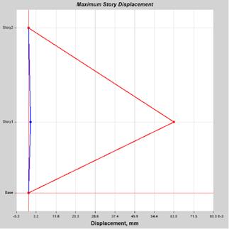
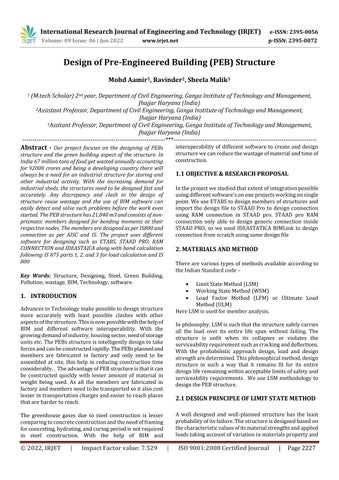
Chart1 TabulatedplotCoordinatesofDisplacement
Someoftheconnectionare
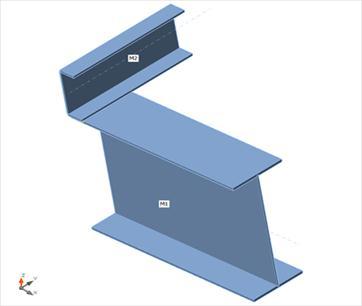
Fig1 Apextypeconnectiondetaildiagram
Configuration
Isapex : Yes
Verticalangle(deg) : 0 Rightbeam Beams
Beamtype : Tapered member
Beamsection : Taper_7
Beaminitialheight : 699.999mm
Beamfinalheight : 699.999mm
Beamlength : 3.35m
Beammaterial : STEEL_275_NMM2
Moment Flangeandwebwelded
Beamside
Topflangeweldtype : Fillet
Topbeamflangeweld: E70XX

D1: Weldsizetotopbeamflange(1/16in) : 4
Bottomflangeweldtype : Fillet
Bottombeamflangeweld : E70XX
D3: Weldsizetobottombeamflange (1/16in) : 4
Weldingelectrodetobeamweb:E70XX
D2: Weldsizetobeamweb
Name Mem N Vy Vz Mx My Mz
LE1 M1 126.6 0.1 121 0 106.6 0 M2 0.1 0 0 0 0 0
LE2 M1 141.8 0.1 91 0 47.1 0 M2 0.1 0 0 0 0 0
Table 7 Summaryofpurlinconnectionresult
Name Value Check status Analysis 100.00% OK Plates 0.0<5.0% OK Welds 0.6<100% OK Buckling Notcalculated
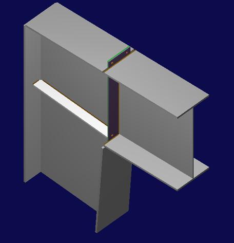
Fig2 Purlinconnection
Volume: 09 Issue: 06 | Jun 2022 www.irjet.net p ISSN: 2395 0072 © 2022, IRJET | Impact Factor value: 7.529 | ISO 9001:2008 Certified Journal |
International Research Journal of Engineering and Technology (IRJET) e ISSN: 2395 0056
Volume: 09 Issue: 06 | Jun 2022 www.irjet.net p ISSN: 2395 0072
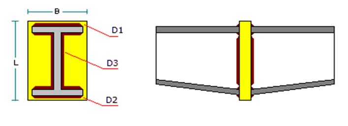
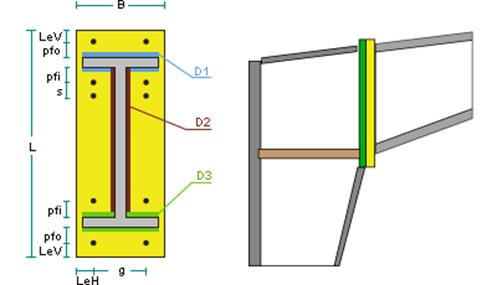
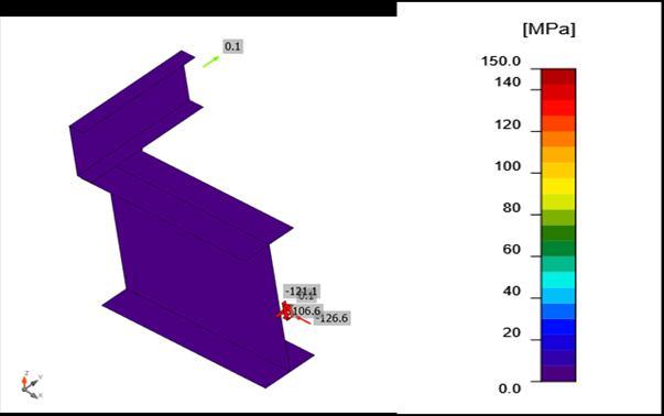
Fig3 PurlinconnectionequivalentstresscheckforloadLE1
Members
Configuration
Isapex : Yes
Verticalangle(deg) : 0
Rightbeam
Beams
Beamtype : Taperedmember
Beamsection : Taper_7
Beaminitialheight : 699.999mm
Beamfinalheight : 699.999mm
Beamlength : 3.35m
Beammaterial : STEEL_275_NMM2
Moment Flangeandwebwelded
Beamside
Topflangeweldtype : Fillet
Topbeamflangeweld: E70XX
D1: Weldsizetotopbeamflange(1/16in): 4
Bottomflangeweldtype : Fillet
Bottombeamflangeweld : E70XX
D3: Weldsizetobottombeamflange(1/16in):4
Weldingelectrodetobeamweb : E70XX
D2: Weldsizetobeamweb(1/16in) : 3
Connectingplate
tp:Thickness : 25.4mm Material : A36
Members
Configuration
Isapex : Yes
Verticalangle(deg) : 0 Rightbeam
Beams
Beamtype : Taperedmember
Beamsection: Taper_7
Beaminitialheight : 699.999mm
Beamfinalheight : 699.999mm
Beamlength : 3.35m
Beammaterial : STEEL_275_NMM2
Moment Flangeandwebwelded
Beamside
Topflangeweldtype : Fillet
Topbeamflangeweld: E70XX
D1: Weldsizetotopbeamflange(1/16in): 4
Bottomflangeweldtype : Fillet
Bottombeamflangeweld : E70XX
International Research Journal of Engineering and Technology (IRJET) e ISSN: 2395 0056
Volume: 09 Issue: 06 | Jun 2022 www.irjet.net p ISSN: 2395 0072
D3: Weldsizetobottombeamflange(1/16in):4
Weldingelectrodetobeamweb: E70XX
D2: Weldsizetobeamweb(1/16in): 3
Connectingplate
tp:Thickness : 25.4mm Material : A36
Existsoppositeconnection: No
General
Beamsection : Taper_7
Beammaterial : STEEL_275_NMM2
Beaminitialheight : 699.999mm
Beamfinalheight : 699.999mm
Beamlength : 6.7m
Verticalangle(deg) : 5.711
Includeflangestiffener: No
General
Supportsection : Taper_2
Supportmaterial : STEEL_275_NMM2
Supportinitialdepth : 749.999mm
Supportfinaldepth : 399.999mm
Supportlength : 5m
Connector
Plateextension: Extendedexternaledge Width : 203.2mm
tp: Platethickness : 6.35mm
Platematerial : A36
Fy : 0.248kN/mm2
Fu : 0.4kN/mm2
Holetypeonplate : Standard(STD)
Flushextensionlength: 25.4mm
Platealignment :Verticalalignment
Externalflangeweldtype: Fillet
Weldtoexternalflange: E70XX
D1: Weldsizetoexternalflange(1/16in): 3
Internalflangeweldtype : Fillet
Weldtointernalflange : E70XX
D3: Weldsizetointernalflange(1/16in): 3
Webweld : E70XX
D2: Weldsizetoweb(1/16in): 3
Bolts
tp: Connectionplatethickness: 6.35mm
Bolts: 1/2"A325N
g: Gage transversec/cspacing: 139.7mm
Holetype : Standard(STD)
Lev: Verticaledgedistance : 31.75mm Leh: Horizontaledgedistance: 31.75mm Boltgroup(externalextension) pfot:Distancefromboltrowstoflange:31.75mm Boltgroup(externalflange)
Boltsrowsnumber : 1 pfit:Distancefromboltrowstoflange :31.75mm Boltgroup(internalflange)
Boltsrowsnumber : 1 pfib:Distancefromboltrowstoflange:31.75mm
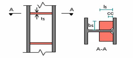
Transversestiffeners Section : PL12.7x76.2x727.65
Fulldepth : Yes Length : 727.649mm bs: Transversestiffenerswidth: 76.2mm cc: Cornerclips : 19.05mm ts: Transversestiffenerthickness: 12.7mm
Material : AS_Class4.6
Weldtype : Fillet
Weldingelectrodetosupport : ASE41XX D: Weldsizetosupport(1/16in) : 3
International Research Journal of Engineering and Technology (IRJET) e ISSN: 2395 0056
Volume: 09 Issue: 06 | Jun 2022 www.irjet.net p ISSN: 2395 0072
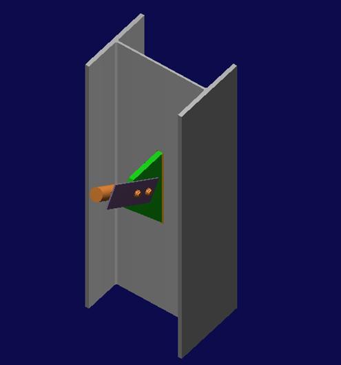
Upper right brace
Gusset General
tg: Thickness: 20mm Material : E250A LV:Lengthoncolumn: 324.458mm
Gusset to Brace connection
General Connectiontype: Bolted Bolts : M_20G8_8
Existingmembers
Rightbeam : No Leftbeam : No
Upperrightbrace : Yes
Upperleftbrace : No
Lowerleftbrace : No Lowerrightbrace : No Alignbeamstotopedge: No Bracingcleatassembly: No Column General Columnsection : Taper_2
Columnmaterial : STEEL_275_NMM2
Columnorientation : Transversal Iscolumnend : No
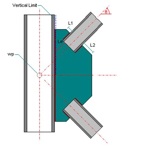
Upper right brace
General Section : Cir0.05_0
Material : Q345 Slopeangle(degrees) : 33.11
Additionalverticalforce: 0kN
Additionalgeometricdata wpx: WPhorizontaldisplacement: 0mm wpy: WPverticaldisplacement: 0mm
Le:Minimumdistancetoothermembers: 25mm
Le1:Leftdistance : 25mm
Le2:Rightdistance : 25mm
Holetype : STD Holetypeongusset : STD np: Numberofrowsofboltslongitudinally: 2 nc: Numberoflinesofboltstransversely: 1 sp: Longitudinalboltspacing: 70mm ae1: Longitudinaldistancetoedge: 45mm ae3: Transversedistancetoedge: 45mm Material : E250A t: Thickness: 5mm Setback : 20mm Weld : E49 Weldsize : 5mm Weldlength : 100mm Weldclearance: 5mm
Gusset to Column connection
General Connectiontypetocolumn:Directlywelded Directlywelded Weldingelectrode : E49 Weldsize : 6 mm
Members
Column Section : Taper_2 Material : STEEL_275_NMM2
2022, IRJET | Impact Factor value: 7.529 | ISO 9001:2008 Certified Journal
International Research Journal of Engineering and Technology (IRJET) e ISSN: 2395 0056
Longitudinaloffset : 0mm
Transversaloffset : 0mm
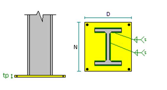
Baseplate
Connectiontype : Unstiffened Positiononthesupport: Center
N:Depth : 460mm
D:Grosswidth : 610mm tp:Thickness: 6mm Material : E250A
Columnweld: E41
s:Columnweldsize : 3mm
OverrideA1/A2ratio : No Shearkeytype : None
Withpedestal : No
Longitudinaldimension : 2500mm
Transversaldimension : 2500mm Thickness : 500mm Material : M40
Includegrouting : No Cover : 70mm Anchor
Anchorposition : Transversalposition Rowsnumberperside : 1 Anchorsperrow : 2
Longitudinaledgedistanceontheplate: 50mm Transverseedgedistanceontheplate : 50mm Headtype : Hexagonal Includelocknut : No Anchor : M 8
Effectiveembedmentdepth : 150mm
Totallength : 166.56mm
Material : Class8.8
Fy : 640N/mm2
Fu : 800N/mm2
SplittingFailure : No
Crackedconcrete : No Non ductilesteel : No
Fastenersweldedtobaseplate: No Leverarm : No
Tensionreinforcement: No Shearreinforcement : No
Fig11 Baseplateconnection
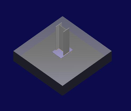
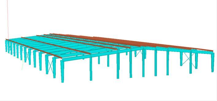
Fig12 RenderviewofthePEBstructurebySTAADpro
Fig13 Sheardiagramofthestructure
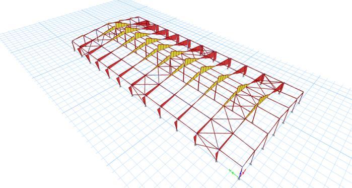
Weareabletodesignthestructureandconnectionbycodal provision and preliminary data. With the use of Etabs and Staad Pro we designed members of the structures and
Volume: 09 Issue: 06 | Jun 2022 www.irjet.net p ISSN: 2395 0072 © 2022, IRJET | Impact Factor value: 7.529 | ISO 9001:2008 Certified Journal | Page2234
International Research Journal of Engineering and Technology (IRJET) e ISSN: 2395 0056
Volume: 09 Issue: 06 | Jun 2022 www.irjet.net p ISSN: 2395 0072
connectionwiththehelpofRAMconnectionandIdeaStatica. Thedataofmodelistransferredfromonesoftwaretoother with help of IFC file or plugins. Both the methods for transferringthedataisn’tcompletelysuccessfulinourcase and some of the members need to redesign for further designing
Thestructureisprefabricatedanditisonlyassembledonthe site. The structure is pre planned according to the site conditions, wind conditions, earthquake forces, MEP loads andtemperaturestresses.Oncetheplanningofstructureis completed, the member is fabricated in the factory and assembledonthesiterequiringlessertimeandfewerman power.AccuracyThememberandconnectionaredesigned specifically for each node and use of Ram connection and Ideastaticaconnectioncandesignedtheconnectiontohighest accuracy. The software designed file can be shared with various software using plugin. The file shared contain designeddatafromparentsoftwarewhichcannowintegrate withotherdataonothersoftwarelikeRevittocreatehighly accurate 3d Model. Low wastage the PEBs structure after designing is fabricated in a factory part by part and only requisiteamountofmaterialiscutfrombiggersheetofrolls toformafabricatedmemberofaPEBandthescrapsfromthe sheetscanbecollectedforrecycling.
Thestructureisprefabricatedanditisonlyassembled onthesite.
[2] T.Subramani and K.Murali (2018) Analytical Study of Tall Building with Outtrigger System with Respect to SeismicandWindAnalysisUsingETABS
[3] Guangfeng Wang (2014) Research on ETABS Steel ToweraTopBuildingStructuralSystem
[4] K. Surender Kumar, N.Lingeshwaran, Syed Hamim Jeelani (2020) Analysis of residential building with STAAD.Pro&ETABS
[5] YongheWua,JianchunMub,ShengqiangLicandHuifeng Xi(2011)DynamicResponseAnalysisonSteel Concrete CompositeFrameBasedonETABS
[6] YongweiSHAN,PaulGOODRUM,CarlHAAS,andCarlos CALDAS(2012)AssessingProductivityImprovementof Quick Connection Systems in the Steel Construction IndustryUsingBuildingInformationModeling(BIM)
[7] NitinK.Dewani,SanjayBhadke(2018)STUDYOFPRE ENGINEEREDBUILDING,IRJET
[8] Mr. Vaibhav Thorat, Mr. Samyak Parekar 2022 Pre Engineering Building as a Modern Era: A Review, IJRASET

[9] Mitaali Jayant Gilbile, S. S. Mane (2020) A Review on Comparative Study on the Structural Analysis and Design of Pre Engineered Building [PEB] with ConventionalSteelBuilding[CSB],IJERT
The structure is pre planned according to the site conditions, wind conditions, earthquake forces, MEP loadsandtemperaturestresses.
Once the planning of structure is completed, the memberisfabricatedinthefactoryandassembledon thesiterequiringlessertimeandfewermanpower.
[10] Angela Acree Guggemos,A.M.ASCE; andArpad Horvath,A.M.ASCE (2005) Comparison of Environmental Effects of Steel and Concrete Framed Buildings
Accuracy The member and connection are designed specifically for each node and use of Ram connection andIdeastaticaconnectioncandesignedtheconnection tohighestaccuracy.
Thesoftwaredesignedfilecanbesharedwithvarious softwareusingplugin.
The file shared contain designed data from parent software which can now integrate with other data on other software like Revit to create highly accurate 3d Model.
[1] Geeta Mehta,BidhanSharmaandAnujKumar,(2016) Optimization of Member Size and Materials for MultistoriedRCCBuildingsusingETABS
MohdAamir,M.Tech,Department ofCivilEngineering,Ganga InstituteofTechnologyand Management,JhajjarHaryana, (INDIA)
Email.Id: aamir.ahmed433@gmail.com

Ravinder,AssistantProfessor, DepartmentofCivilEngineering, GangaInstituteofTechnology andManagement,Jhajjar Haryana,(INIA)
Email.Id: ravinderpanwar7043@gmail.com
International Research Journal of Engineering and Technology (IRJET) e ISSN: 2395 0056
Volume: 09 Issue: 06 | Jun 2022 www.irjet.net p ISSN: 2395 0072
SheelaMalik,AssistantProfessor, DepartmentDofCivil Enginnering,GangaInstituteof TechnologyandManagement, JhajjarHaryana,(INDIA) Email.Id: sheelamalik2209@gmail.com

2022, IRJET | Impact Factor value: 7.529 | ISO 9001:2008 Certified Journal |