International Research Journal of Engineering and Technology (IRJET) e ISSN: 2395 0056

Volume: 09 Issue: 06 | June 2022 www.irjet.net p ISSN: 2395 0072
International Research Journal of Engineering and Technology (IRJET) e ISSN: 2395 0056
Volume: 09 Issue: 06 | June 2022 www.irjet.net p ISSN: 2395 0072
Mrs. Dhanashree Patil is currently pursuing master’s degree program in Structural engineering in School of Civil Engineering, Sandip University, Nashik, India. Dr. Sachin Mulay, Professor, Department of Structural Engineering, Sandip University, Nashik, India ***
Abstract The expanded count of terrorist attacks for the most part over the most recent couple of time has demonstrated that impact of Blast loads on structures is a genuine issue which we ought to be considered during configuration procedure of structures in spite of the fact that these sorts of terrorist strikes areextraordinarycasesmadeby man dynamic loads i.e. Blast loads are really needed to calculate with great attention just like windandseismicloads. Also, the investigation of behavior of ferrocement composites under Blast loading that are utilized as lasting formwork in conventional reinforced concrete structures is introduced in this report. Single ferrocement panel specimens are tested experimentally and analytically under Blast load and also the load deflection behavior is then studied.
The main aim of this research is to compare the behavior of the ferrocement concrete Blast loading. In this research the Ferrocement panel with layered mesh modelled in ANSYS Workbench.
The panels with different sizing are tested analytically under blast loading in ANSYS Workbench and compared behavior of ferrocement panels.
Key Words: Ferrocement, Blast resistant design, blast waves, explosive effect, finite element method.
Themainaimofthisresearchistostudythebehaviorofthe ferrocementconcreteunderBlastloadingandstudyofBlast resistance of ferrocement concrete in comparison with normal concrete. Blasts and types of Blasts have been explainedinbrieffirstly.Furthermore,thenormalpartsof Blast procedure had displayed to explain the impacts of Blastsonstructures.Toobtainasuperiorcomprehensionof BlastsandattributesofBlastswillempowerustomakeBlast safestructureplanningandconsiderablyextraproductively. Fundamentalmethodsforexpandingthelimitofastructure to give protection from the dangerous impacts is talked about both with a planning and designing methodology. Harm to the peoples, deaths and social frenzy are aspects thatmustbelimitedifthedangerofbomberactivitycan'tbe ceased. Planning and design of the structures to be completely bang safe is certifiably not a reasonable and
affordable alternative, present time designing and engineering learning can improve the new as well as old edificestoreducetheeffectsofanBlast
➢Toanalyzebehaviorofferrocementcompositesunderthe blastloadingbyusingFiniteElementMethod
➢ Tostudythebehaviortheferrocementpanelsundergoing blastloading.
➢ Comparative study of ferrocement panels with varying thicknessagainstblastloading.
Table 1: MaterialProperties(adoptedforFerrocement PanelModelingofsize600mmx600mmx18mm(2Layer ofMeshes))
Property Mortar WeldedMesh Compressive strength [N/mm2] (experimentaldata)
Young’smodulus(E) [N/mm2] (theoreticaldata)
53 1.2 mm diameter 15 mm ×15 mm Spacing
2000 1.3×10^5N/mm2
Poisson’s ratio μ (theoreticaldata) 0.11 0.3
Density[kg/m3] (theoreticaldata) 2080 7850
International Research Journal of Engineering and Technology (IRJET) e ISSN: 2395 0056
Volume: 09 Issue: 06 | June 2022 www.irjet.net p ISSN: 2395 0072
Kinney [10] presents a formulation that [10] is based on chemicaltypeBlasts.Itisdescribedbyfollowingequation and has been used extensively for computer calculation purposes.
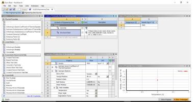
Fig 1(a)Slab
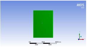
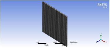
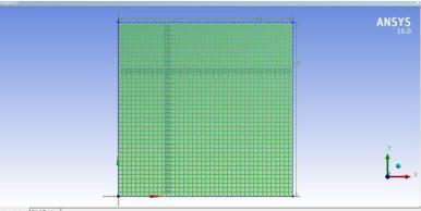
Fig 1(b)Mesh
Ablastisaquickreleaseofpotentialenergydescribedbya splendidflashdischargedasacapableofbeingheardblast. Some portion of energy is discharged as warm radiation streakandasectioniscoupledintotheairasairimpactand into the soil ground as ground shocks both as radially expandingshockwaves.
Calculation of Peak Overpressure: EquivalentofTNT 100g ScaledDistance
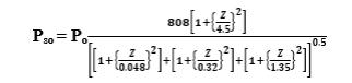
WhereZ(m/kg1/3)isthescaleddistance,EquationandP0is theambientpressure.
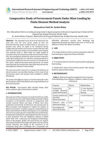
5.3 ANSYS
5.3.1 ANSYS INC
Table3.BlastPressurefor100TNTcharge
Sr. No. Stand off Distanceincm ScaledDistance (Z) Pressure (KN/mm2) 1 20,25and30 4.25 6.122
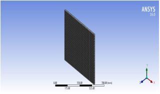
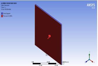
Fig.2FerrocementPanel
5.3.2 MODELING IN ANSYS OF FERROCEMENT PANLES UNDER BLAST LOADING
Where,Risthedistancefromthepointofinterest(m)tothe detonationsourceandWistheweight(moreabsolutely:the mass)oftheexplosive(Tons).
For20cmStandoffDistance, Z= 4.25m
Fig.3AddingmaterialinAnsys
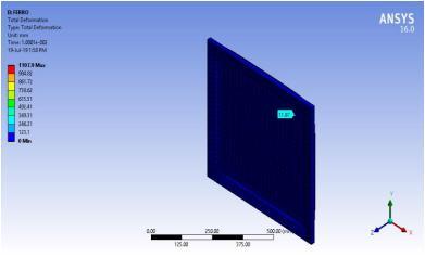
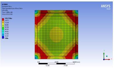
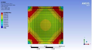
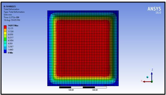
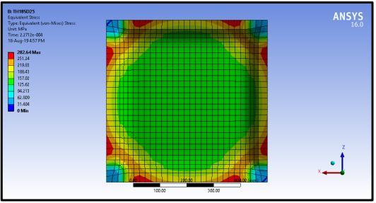
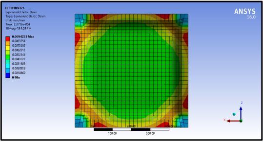
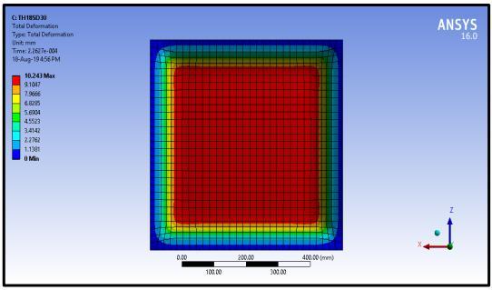
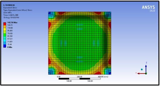
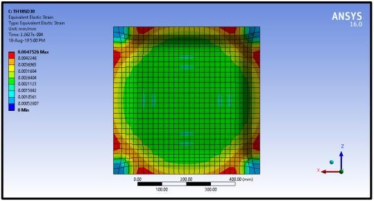
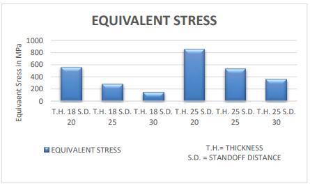
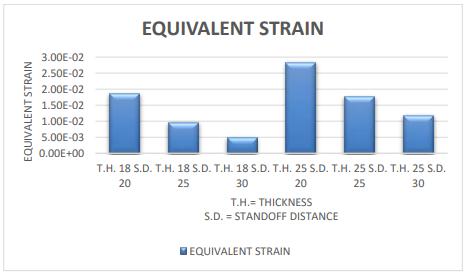
6.7 Ferrocement Panel Results for 2 Layered wired Mesh And 18mm Thickness.
Table4.FerrocementPanelResults2 LayeredwiredMesh And18mmThickness.
Result Ferrocement Panel Standoff distance 20 25 30
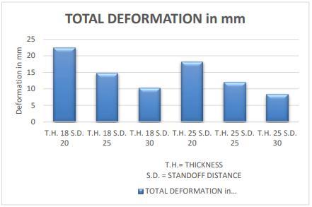
TOTAL DEFORMATION inmm
22.446 14.817 10.243
EQUIVALENT STRESSMPa 561.79 282.64 142.56 EQUIVALENT ELASTIC STRAIN
0.0087 0.00942 0.00475
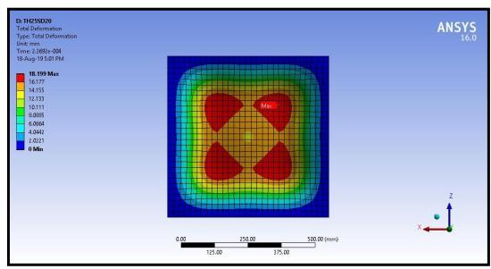
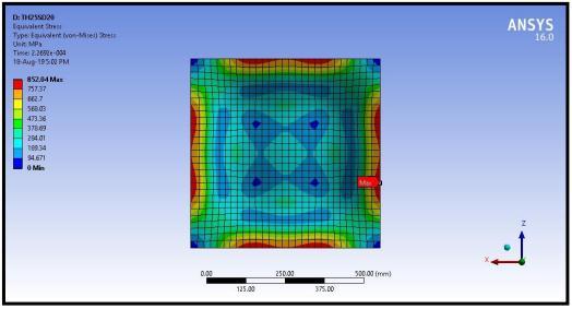
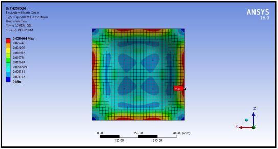
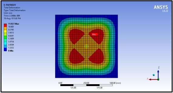
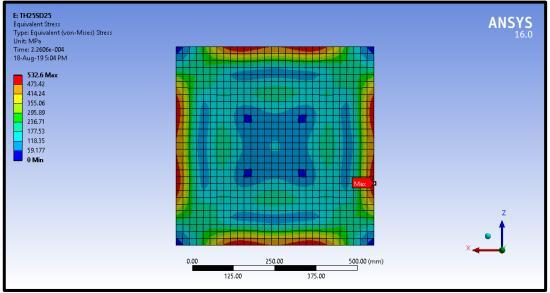
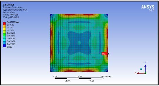
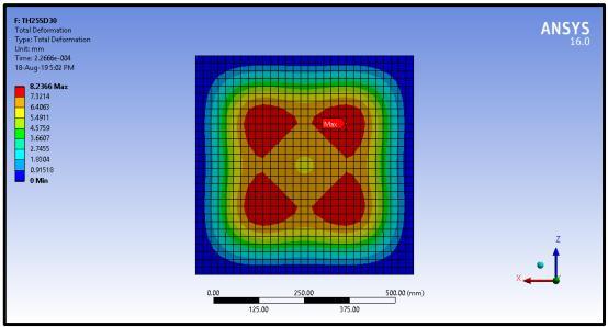
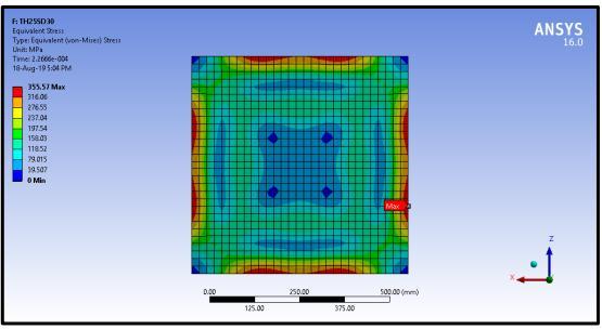
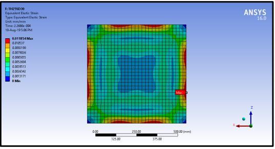
6.8 Ferrocement Panel Results for 3-Layered wired Mesh And 25mm Thickness
Table 5FerrocementPanelResultsfor3 Layeredwired MeshAnd25mmThickness.
Result Ferrocement Panel Standoff distance 20 25 30
TOTAL DEFORMATION inmm
18.199 11.927 8.2366
EQUIVALENT STRESSMPa 852.04 532.6 355.57
EQUIVALENT ELASTIC STRAIN
0.0284 0.0177 0.0118
It is observed that total deformation for ferrocement panelwith18mmthicknessisaverage23.98%greater than deformation in 25 mm thickness ferrocement panel.
Equivalentstressesdevelopedinferrocementpanels25 mm thickness are nearly 46.97 % more than stresses developedin18mmthicknessferrocementpanel.
Equivalent Elastic Strain developed in ferrocement panels25mmthicknessarenearly58.63%morethan stresses developed in 18mm thickness ferrocement panel.
The proposed methodology can be used for improvementindesigncriteriaforferrocementorother concrete composite elements subjected to air Blast loads.
ForlongerStand Offdistancebothpanelswith25mm thicknessaremoredurableandprovidegoodresistance toBlastascomparedto18mmthicknesspanels,sofrom designpointofview25mmthickferrocementpanelis preferred.
In case of edifices which possess greater threat of occurrence of Blast, ferrocement panels with more thickness and a greater number of wire meshes is recommended.
Withdeepsenseofgratitude,iwouldliketothanksallthe peoplewhohavelitmypathwiththeirkindguidance.Iam verygratefultotheseintellectualswhodidtheirbesttohelp duringmyprojectplanningwork.Itismyproudprivilegeto expressdeepsenseofgratitudetoProf.Dr.A.S.Maheshwari, Associate Dean of SOET, Sandip University Nashik, for his comments and kind permission to complete this project planning work. We remain indebted to Prof. DR. Sachin Mulay, Civil Department for her timely suggestion and valuable guidance. The special gratitude goes to project guide, staff members and technical staff members of Civil Department for their excellent and precious guidance in completionofthiswork.
1. ANSYS AUTODYN User Manual (2007), Version 16.0, Concord(CA,USA)CenturyDynamics,p.528
2. IS 4991 (1968), Criteria for blast resistant design of structuresforexplosionsaboveground.,BIS,India
International Research Journal of Engineering and Technology (IRJET) e ISSN: 2395 0056
Volume: 09 Issue: 06 | June 2022 www.irjet.net p ISSN: 2395 0072
3.U.S.ArmyCOE(USACE).(1990).“Structurestoresistthe effects of accidental explosions.” TM 5 1300, Dept. of the Army,Washington,DC.
4.Unified Facilities Criteria (UFC 3 340 02), (2008), “StructurestoResisttheEffectsofAccidentalExplosions”.
5.Alok Goyal, “Blast resistant design: Critical issues, proceedingsofthesixthstructuralengineeringconvection”, ppIPXI 1 10,Dec2008
6.RaySinghMeena,BEthesisreport,NationalInstitute of Technology,Rourkela(2009).
7.P.B.Sakthivel,“Ferrocementconstructiontechnologyand itsapplication AReview”,TheInternationalConferenceon Structural Engineering, Construction and Management at Kandy,SriLankaonDecember15 17,2011,pp2 12
8.M.Saleem,“FlexuralBehaviorofFerrocementSandwich panels”,CementConcreteComposites,Jan 1991pp21
9.A.Jagannathan“Studyofflexuralbehaviorofferrocement slab reinforced with PVC coated weld mesh” IJERD, Vol 1, July 2012,pp50 57
10.R.Phalke“FlexuralBehaviourofFerrocementSlabpanels using welded square mesh by incorporating steel fibers” IJRET,Vol 3,May 2014,pp756 763.
11.Kinney G, Graham K (1985) Explosive shocks in air. Springer,NewYork
12.RaySinghMeena,BEthesisreport,NationalInstituteof Technology,Rourkela(2009).
13.Mir.M.Ali,“Protectivedesignofconcretebuildingsunder blast loading” submitted to School of Architecture, Structures Division, University of Illinois at Urbana Champaign,USA