1
The Voltage Fed Series Compensation Based ZVZCS Topology and Its Tuning Method for Wireless Electrical Vehicle Battery Charger
Prathyusha Padavala1, D Dinesh Kumar2
2
***
Abstract: Recently available topologies of high frequency converter power converter system inductive power transfer (IPT) uses either zero voltage switching (ZVS) or zero based power converters (ZCS) while keeping the sinusoidal current close to the range limited power transfer. However, achieving ZVS or ZCS for all simultaneous power transfers remains a challenging task for IPT systems. In this article, we developed the zero voltage zero current switching (ZVZCS) IPT topology and its proposed switching pattern. ZVS is achieved by enhancing the compensation of the old series and in addition, using an auxiliary network to achieve ZCS. The proposed concept is validated using MATLAB / Simulink based analogs for battery load resistance.
Keywords: Battery chargers, dc–dc power converters, electric vehicles (EVs), inductive charging, soft switching, wireless power transmission
1.INTRODUCTION
The increasingly the global economy is facing the destructionoffuelresourcesandthedangerousdisruptionof ecosystems. In addition, it has encouraged the emergence of sustainable technologies that lead to new actions for major carbon suppliers, namely, transportation [1], [2]. Therefore, electric vehicles (EVs) were adopted as a solution to reduce the environmental effects caused by carbon based fuels [2], [3]. In addition, the EVs market opens up new opportunities for people to extend the lifespan of low cost transportation [1], [3]. In the past, battery technology (BT) and power generation technology were the limits on which to remove EVs from market success. However, BT has emerged with highenergydensity,lowweight,andhighefficiencyoverthe pastfewdecades[4].Additionally,anefficientenergy saving device improves overall performance while in use with a suitablepowergenerationcircuit.Dc dcpowerconfiguration withlowpowerloss,durability,reliablepowertransmission, and additional charging charge cycles are used by researchersandindustry[1] [4].

Today, efficient, fast chargers are used for short distance driving with public safety concerns. In the current situation,
inductivepowertransfer(IPT) basedmodelsareacceptedas safe battery charging (BC) solutions during stationary and flexible EV mode. Compensation networks are introduced to prevent impedance of the circuit to improve the overall efficiency of the converter. However, the number of active and passive components of circuits includes configuration difficulties [5]. The right solution also improves driving distance, maintenance cycle, carbon reduction, and end user economy. Therefore, converter selection plays an important role in EV market movement. Therefore, it supports the reduction of environmental problems generated by technologytravelissues[6].
Classical series series capacitor compensation based IPT topology is one of the industry's most widely accepted network systems due toits simplestructureand operational stability of various coils [7]. This network produces a low cost solution but jeopardizes its efficiency, power transmission, high volume peaks, and controlling different upload accuracy. In [7], a phase control algorithm was introduced to improve efficient bandwidth; however, costs result as a complex control strategy of varying frequency. In [8], the problems generated by the variable frequency are minimized by defining the control boundary at the appropriate frequency range. The control solutions introduced in [7] and [8] only support clam to provide maximum efficiency by maintaining zero power conversion (ZVS) in the IPT system. The development of topological in [9]developedanewcoilsupportnetworkusingacentralL C series compensating for both the transmitter and the receiver end. This suspension increases the weight on the sideofthecar,whichisreducedby[10],byplacingbothcoils on the main side. The solution presented in [9] and [10] provides support for magnetic fluctuations in the case of misunderstandings but reduces the aesthetic advantages in calculating and controlling performance. The solution to the problems introduced in [9] and [10] as a remote network to support IPT is addressed [11] by combining the H bridge high frequency transformer with the L C tank network. However, it increases the size, weight, and volume of the entire system while minimizing the maximum value efficiency.
©
Journal | Page2172
International Research Journal of Engineering and Technology (IRJET) e ISSN:2395 0056 Volume: 09 Issue: 06 | June 2022 www.irjet.net p ISSN:2395 0072
2022, IRJET | Impact Factor value: 7.529 | ISO 9001:2008 Certified
PG Scholar, EEE, M.Tech (Electrical Power Systems),Audisankara College of Engineering and Technology, Gudur, India
Assistant Professor, Department of EEE, Audisankara College of Engineering and Technology, Gudur, India
International Research Journal of Engineering and Technology (IRJET) e ISSN:2395 0056
Volume: 09 Issue: 06 | June 2022 www.irjet.net p ISSN:2395 0072
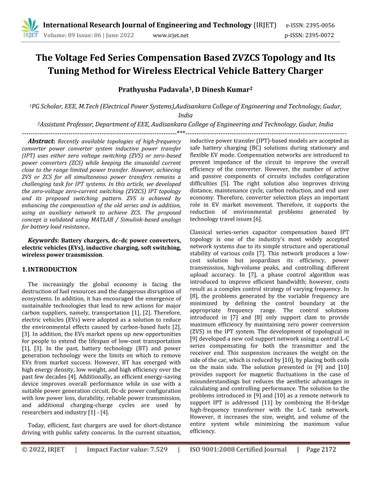
Therefore a solution as the reconstruction of the partial networkisintroduced[12] [17]toreducetheproblemsthat havebeenstrippedoftheadditionalsoundtankseparatedby a magnet. In [12] and [13], an equivalent filter network is installed with transformer coils that are freely connected to improve long term system performance. However, these topologies use magnetically induced inductors, which increase weight, volume, complexity in the tuning process, and reduce efficiency. These issues are resolved in [14] and [15]throughunequalcompensationusingtheLCC Cnetwork configuration. Analysis of the claims presented in [12] [15] iscomparativelystudiedin[16]and[17],anditisfoundthat in the same coil design, the LCC LCC network is suitable for staticIPTandLCC CI PowerfulIPT.however,itsuffersfrom distortionsinthecase ofcartopologyandpermitvariations. Therefore, Zhang et al. [16] and Li et al. [17] direct finding a differentsolutionusingtheC Ccompensationchain.In[18] [20], a flexible stabilization solution for a wide range of operation, improved efficiency, tightly integrated dc dc transformer based converter is introduced. In [21] and [22], an auxiliary network was adopted to improve the performance of sound IPT topology based on [18] [20]. Consistent losses are increased due to other magnets while stable performance and improved efficiency are achieved. Similarly, a solution for IPT based IPT series based on C C was introduced in [23]. At this point of view, IPT with auxiliary cycle can reduce the problems that exist in a network based voltage source inverter (VSI). In this article, the proposed topology uses an old L C compensation consistingofauxiliarycomponentsofsmallsizetomakeZVS and current converted zero (ZCS). The proposed topology providesaconstantoutputvoltageeveniftheinputissubject to a wide range of voltages. Current output can be easily controlled from the input side voltage, eliminating the processorrequirementforhighpowercontroloperation,and conversion costs are effectively reduced. The laboratory prototypewasdesignedandtestedforbatteryresistanceand full range BC. Figure 1 shows a general overview of the proposed topology in which the two converter phases are controlled using modified pulse width modulation (MPWM) separately.The pulsesareproducedat85kHz tochangethe frequencyinMPWMmodetoreachzero voltagezero current switching (ZVZCS) to bring power up to 1.1 kW, and performance results are presented. The remaining topic is organized into subsequent sections. The principle of operation ofthe proposedconverterisdiscussedinPhaseII. A circuit design design study is presented in Phase III. Imitation effects are discussed in Section IV. Finally, the conclusionismadeSectionV.
2.OPERATING PRINCIPLE OF THE PROPOSED CONVERTER
Active switches S1 − S4 the main side and diodes D5 D8 on the second side form a bridge H (standard). In addition,
Ca1 and Ca2 act as a potential separator for inputs with AncillaryLAandTA tomaintaina slightswitchingfeaturein the BC. The primary and secondary side of the circuit are connected by L1 and L2 with C1 and C2, respectively. Conversion performance is controlled using MPWM in [22]. The following considerations are considered in order to understand the operating principle of the proposed converter.
• All active and passive devices include transformer, dc source, switches, diodes, and capacitors suitable for integratinginternalswitchingpowerandpower.
• Resistance to electrical circuit of the inductor and interwindingcapacitanceofthetransformerisignored.
• The voltage divider capacitors (Ca = Ca1 = Ca2) and CF are large enough to maintain a constant voltage at the input andoutputterminalsoftheconverter.
•TheeffectsofmagnetizinginductanceonTAareignored.
Fig1Generalconfigurationofwirelessbatterycharger topology
A. Operation of Proposed Converter
Theoperatingprincipleoftheproposedtopologyinsteady state is divided into eight modes (modes I VIII) as shown in Fig.2andtheoperatingwaveformsareshowninFig.3.1)
1) Mode I (t0 ≤t<t1), Fig.2(a):Beforethefastt0,thelagging current(IL1+ILA)flowsfromD1andS2,Therefore,witht0 instantly, switch S1 is turned on with ZVS. In addition, potential differences between AC and CB are created and presentILA startrisingfrom ILA(t0)
© 2022, IRJET | Impact Factor value: 7.529 | ISO 9001:2008 Certified Journal | Page2173
International Research Journal of Engineering and Technology (IRJET) e ISSN:2395 0056
Volume: 09 Issue: 06 | June 2022 www.irjet.net p ISSN:2395 0072
8) Mode VIII (t7 ≤ t <t8), Figure 2 (l): During this operation, theS2switchisONwithZVSandcurrentshiftsfromD2toS2.
B. Operation of the Ancillary Network
2) Mode II (t1 ≤t < t2), Fig. 2(b) and (c): Before t0,switch S1is conductingandswitchcurrentdifference(iS1 iS2)isflowing from TA (ITA1+ ITA2= ILA).
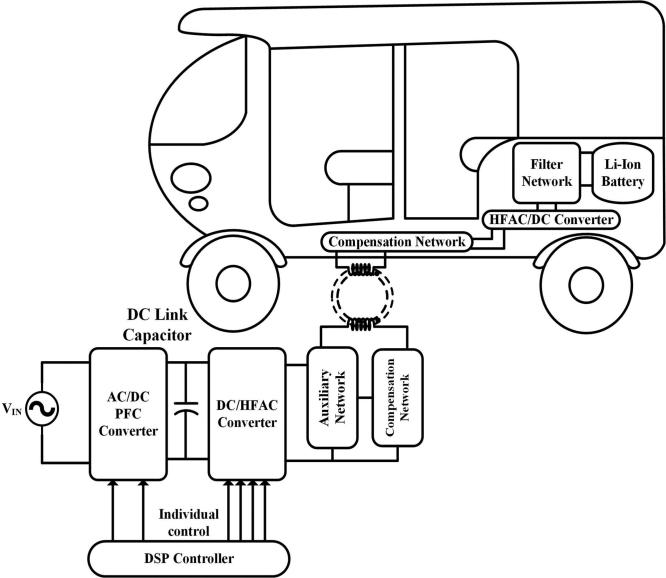
Applying KCL at points A and B and using low energy conservation
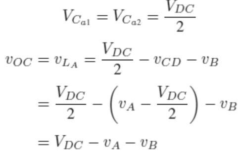
The ancillary coil resonant network and transmitter are shown in Fig. 5. The voltage across LA is obtained by using KVLas
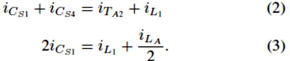
Atthebeginningofthismode,S1isOFFwhenS3isclosed,S4 isalreadyOFF,andS2isstillrunning.ThemaininductanceL1 isnowdisconnectedfromthedcpowersource,andIL1+ILA 2 starts charging the peracetic capacitor CS1 switch. With fastert11,VCS1accessesVDC.Aftert11,IL1findsitswayby forcing a change in ILA. Inductor LA rejects this change and thecurrentstartfromS2toS4,whichreleasesCS4.Afterthe CS4 voltage reaches zero, the D4 opens and this free movementleadstoadecreaseofIS2tozeroorZCStotheS2 switch.
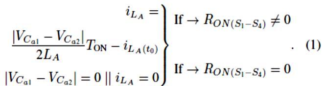
Expression shows the waveform of vOC= VLA, which is complimentary of vAB. This shows the current in LA is high for light loading condition and complimentary for heavy loading condition. When the voltage vAB= VDC or VDC and vCa1 = vCa2 = VDC 2 than from expression (9) VLA = 0. Therefore, current in inductor LA remains unchanged. The valueof iLAisexpressedwhen vCa1 = vCa2andeither S1 S2 or S3 S4inONstate.
4) Mode IV (t3 ≤t<t4), Fig. 2(f): Inthismodeofoperation,the S4 is turned on by ZVS as D4 is turned on and the voltage across the entire S4 is close to zero. ILA current inductor current grows linearly in a straight line after acquiring its negativepeak.
5) Mode V (t4 ≤ t <t5), Figure 2 (g): In this mode, S3 is unlocked with ZVS. IAB begins to follow the sinusoidal waveform,andthevoltageacross S3,S4iszeroasitspathis completed.
6) Mode VI (t5 ≤ t <t6), Figure2(h)and(i):Thismodestarts with CLOSING S3, triggering CS3 charging up to VDC in t51. ILA inductor current decreases after receiving its peak and IL1,ILAforcesIS4tolowertheZCSshutdownstate.
7) Mode VII (t6 ≤ t <t7), Figure2(j)and(k):Inthismode,S4 isOFF inZCSandVCS4goesuptoVDCin t61.Aftert61,ILA beginstoputthecaseonthepositiveside.DiodesD1andD2
OPENandtheresponsepowertothesource.
©
Certified Journal | Page2174
2022, IRJET | Impact Factor value: 7.529 | ISO 9001:2008
International Research Journal of Engineering and Technology (IRJET) e ISSN:2395 0056
Volume: 09 Issue: 06 | June 2022 www.irjet.net p ISSN:2395 0072
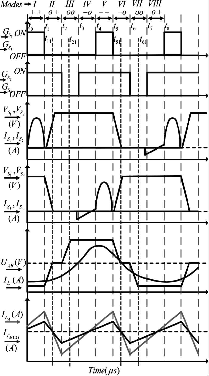
Fig2Operatingmodesofproposedbatterychargertopology.
Fig3Simplifiednetworkwithbatteryloadrefereedat transmittercoilside
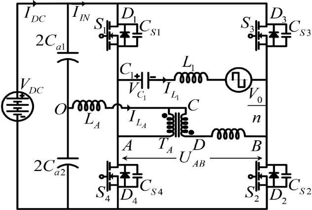
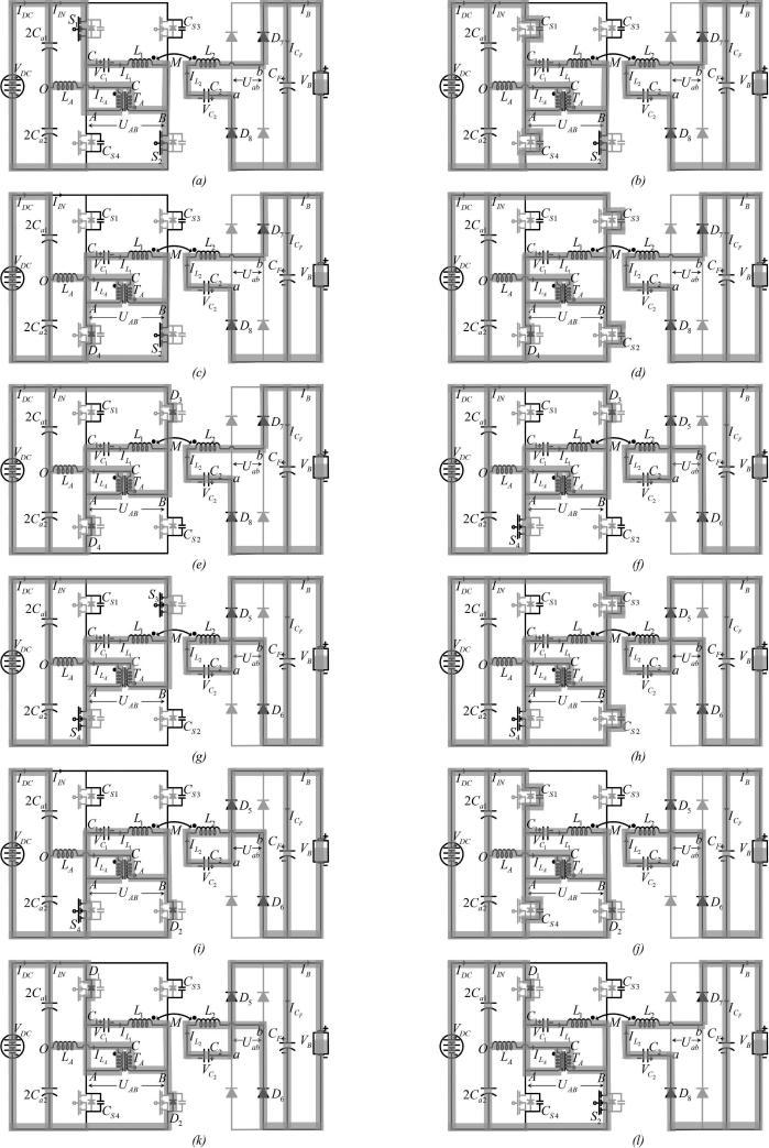
Fig4Theoreticaloperatingwaveformofproposedwireless convertertopology.
3.RESULTS
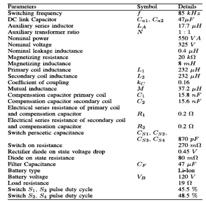
The operational principle of the topology of the proposed converter is verified by modeling, modeling, and hardware testing.Thecircuitparametersinthesimulationaretunedin theworkspacetounderstandthebehavioroftheconverter.
The simulation of the proposed topology was performed on MATLAB / Simulink using key components, as shown in Figure10.UnlockZVSforS1 S4.inFig.4andTableI.Agood source of dc is placed in a series with a resistor (nΩ) and an inductor (nH). MOSFET switches from SimPowerSystem
© 2022, IRJET | Impact Factor value: 7.529 | ISO 9001:2008 Certified Journal | Page2175
International Research Journal of Engineering and Technology (IRJET) e ISSN:2395 0056
Volume: 09 Issue: 06 | June 2022 www.irjet.net p ISSN:2395 0072
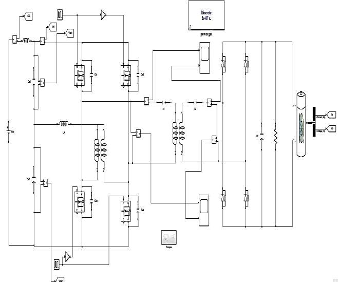
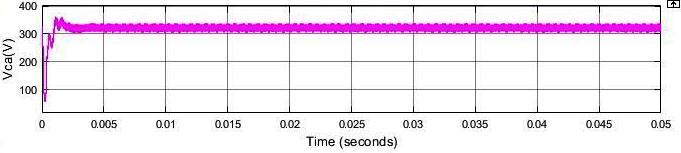
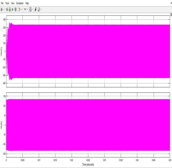
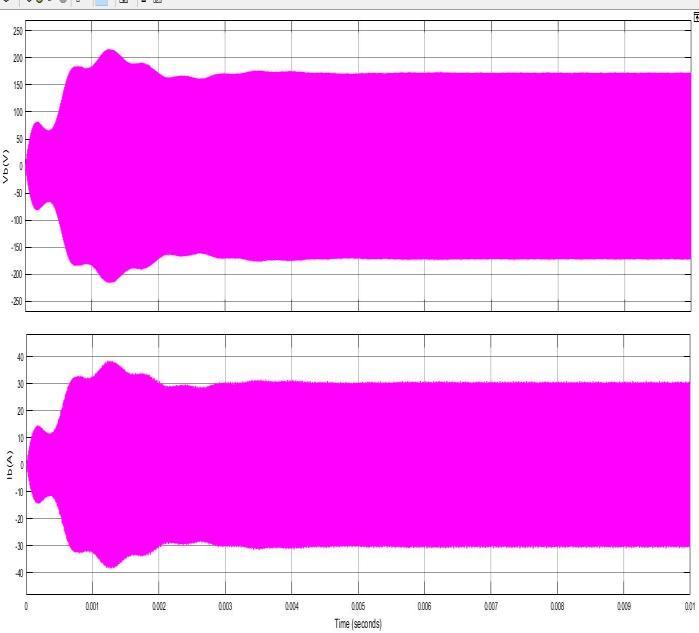
Librarywithapowerof0Ωand870pFasa snubberusedto mimic the H bridge component of the dc dc converter. The auxiliary transformer is contracted by a linear transformer and a transmitter, the receiving coils from the mutual inductance. Figure 10 shows the ZVS switch for the ZVS switchS1toS4,asthevoltageacrosstheswitchreacheszero, thegatepulse isgiven tothatparticularswitch toturn iton. In Fig. 11 (a) and (b), ZCS turn ON switch S2 and S4 are shown.Thecurrentfromtheswitchbecomeszerobeforethe gateknockiscomplete.Itisthereforesaidthattheproposed wirelessconvertersavesZCZVS.Themaximumvoltageofthe compensation capacitor is selected by considering the performance of VC1, as shown in Fig. 12. In Figure 13, the input feature of the main network side is shown. These resultsshowthesmallamountofinputdc linkcapacitordoes not affect the performance of the converter. The function of the BC converter is shown in Fig. 14 (a) (d). It appears in Fig. 14 (a) and (b) that the interference is minimal, whereas the normal charger interferes with BC voltage and current, which reduces battery life and reduces the efficiency of the charger, while the natural voltage and power supply in Fig. 14(c)and(d)withouttheuseofaresidualcircuit.Thecircuit performance provides 93.5% efficiency with the parameters shown in Table I. The efficiency of the output parameters is controlled by updating the switching frequency and output poweriscontrolledbychangingtheinputvoltage.
Fig6SimulationofProposednetworkconfigurationofEV batterycharger
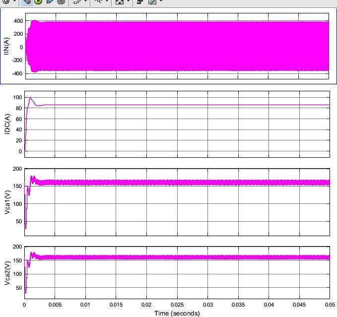
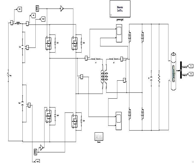
Fig5SimulationofSimplifiednetworkwithbatteryload refereedattransmittercoilside
Fig7Simulatedresultsofinputsidecharacteristicofthe primaryNetwork
©
Page2176
2022, IRJET | Impact Factor value: 7.529 | ISO 9001:2008 Certified Journal |
International Research Journal of Engineering and Technology (IRJET) e ISSN:2395 0056
Volume: 09 Issue: 06 | June 2022 www.irjet.net p ISSN:2395 0072
TableI:Simulationdesignparameters
Fig8Batterychargingvoltageandcurrentusingthe auxiliarycircuit
Fig9Batteryvoltageandcurrentwithoutusingthe auxiliarycircuit
4.CONCLUSION
In this article, a series of voltage compensation Fed based on the ZVZCS topology and its method of repairing a battery charger for an electric wireless car is proposed. Appropriate modificationisintroducedinthefull bridge dc dcconverter, and enhanced functionality with a wide range of input variablesisachieved.Theneedforahigh powerprocessoris eliminated, which further reduces overall costs. Theoretical analysis and modeling were presented to determine ZVZCS with reduced control complexity. The simulation results confirmedtheZVZCSstatus oftheproposedtopologyforthe fullwidthoftheload.Thesolutionprovidedproducedasmall rippleattheinput/outputvoltageandcurrentwhileusinga low dc connector value, and filter volume values, respectively. An acceptable efficiency of 91.26% is achieved inbothbatteryandresistiveloads.
REFERENCES
[1] M.Granovskii,I. Dincer, and M.A.Rosen,“Economicand environmental comparison of conventional, hybrid, electric and hydrogen fuel cell vehicles,” J. Power Sources,vol.159,no.2,pp.1186 1193,2006.
[2] S. B. Peterson, J. Whitacre, and J. Apt, “The economics of using plug in hybrid electric vehicle battery packs for gridstorage,”J.PowerSources,vol.195,no.8,pp.2377 2384,2010
[3] Y.Zhou,M.Wang,H.Hao,L.Johnson,andH.Wang,“Plug in electric vehicle market penetration and incentives: A
©
|
7.529 |
Certified Journal | Page2177
2022, IRJET
Impact Factor value:
ISO 9001:2008
International Research Journal of Engineering and Technology (IRJET) e ISSN:2395 0056
Volume: 09 Issue: 06 | June 2022 www.irjet.net p ISSN:2395 0072
global review,” Mitigation Adaptation Strategies Global Change,vol.20,no.5,pp.777 795,2015.
[4] B. Nykvist and M. Nilsson, “Rapidly falling costs of battery packs for electric vehicles,” Nature Climate Change,vol.5,no.4,pp.329 332,2015.
[5] W.ZhangandC.C.Mi,“Compensationtopologiesofhigh power wireless power transfer systems,” IEEE Trans. Veh.Technol.,vol.65,no.6,pp.4768 4778,Jun.2016.
[6] K. Mude and K. Aditya, “Comprehensive review and analysis of two element resonant compensation topologies for wireless inductive power transfer systems,”Chin.J.Elect.Eng.,vol.5,no.2,pp.14 31,2019.
[7] Y. Jiang, L.Wang, Y.Wang, J. Liu, X. Li, and G. Ning, “Analysis, design, and implementation of accurate ZVS angle control for EV battery charging in wireless high powertransfer,”IEEETrans.Ind.Electron.,vol.66,no.5, pp.4075 4085,May2019.
[8] Y. Jiang, L.Wang,Y.Wang, J. Liu, M.Wu, and G. Ning, “Analysis,design,andimplementationofWPTsystemfor EV’s battery charging based on optimal operation frequency range,” IEEE Trans. Power Electron., vol. 34, no.7,pp.6890 6905,Jul.2019.
[9] D. H. Tran, V. B. Vu, and W. Choi, “Design of a high efficiency wireless power transfer system with intermediate coils for the on board chargers of electric vehicles,” IEEE Trans. Power Electron., vol. 33, no. 1, pp. 175 187,Jan.2018.
[10]S. Moon and G. W. Moon, “Wireless power transfer system with an asymmetric four coil resonator for electric vehicle battery chargers,” IEEE Trans. Power Electron.,vol.31,no.10,pp.6844 6854,Oct.2016.
[11]O.C.Onar,M.Chinthavali,S.L.Campbell,L.E.Seiber,and C. P. White, “Vehicular integration of wireless power transfer systems and hardware interoperability case studies,” IEEE Trans. Ind. Appl., vol. 55, no. 5, pp. 5223 5234,Sep./Oct.2019.
[12]S.Li,W.Li,J.Deng,T.D.Nguyen,andC.C.Mi,“Adouble sided LCC compensation network and its tuning method for wireless power transfer,” IEEE Trans. Veh. Technol., vol.64,no.6,pp.2261 2273,Jun.2015.
[13]C. Liu, S. Ge, Y. Guo, H. Li, and G. Cai, “Double LCL resonant compensation network for electric vehicles wireless power transfer: Experimental study and analysis,” IET Power Electron., vol. 9, no. 11, pp. 2262 2270,2016.
[14]C. Xiao, D. Cheng, and K. Wei, “An LCC C compensated wireless charging system for implantable cardiac pacemakers: Theory, experiment,and safety evaluation,” IEEE Trans. Power Electron., vol. 33, no. 6, pp. 4894 4905,Jun.2018.
[15]Y.Chen,H.Zhang,S. J.Park, andD. H.Kim, “Aswitching hybrid LCC S compensation topology for constant current/voltage EV wireless charging,” IEEE Access, vol. 7,pp.133924 133935,2019.
[16]Y. Zhang, Z. Yan, T. Kan, Y. Liu, and C. C. Mi, “Modelling and analysis of the distortion of strongly coupled wireless power transfer systems with SS and LCC LCC compensations,” IET Power Electron., vol. 12, no. 6, pp. 1321 1328,2019.
[17]W. Li, H. Zhao, J. Deng, S. Li, and C. C. Mi, “Comparison study on SSand double sided LCC compensation topologies for EV/PHEV wirelesschargers,” IEEE Trans. Veh.Technol.,vol.65,no.6,pp.4429 4439,Jun.2016.
[18]G. N. B. Yadav and N. L. Narasamma, “An active soft switched phaseshiftedfull bridge dc dc converter:Analysis, modeling, design, and implementation,”IEEE Trans. Power Eleron., vol. 29, no. 9,pp.4538 4550,Sep.2014.
[19]M. Pahlevaninezhad, P. Das, J. Drobnik, P. K. Jain, and A. Bakhshai, “Anovel ZVZCS full bridge dc/dc converter used for electric vehicles,” EEETrans. Power Electron., vol.27,no.6,pp.2752 2769,Jun.2012.
[20]V. R. K. Kanamarlapudi,B.Wang, P. L. So, and Z.Wang, “Analysis,design,andimplementationofanAPWMZVZCS full bridge dc dc converter forbattery charging in electricvehicles,”IEEETrans.PowerElectron.,vol.32,no. 8,pp.6145 6160,Aug.2017.
[21]J. K. Nama, M. Srivastava, and A. K. Verma, “Modified inductive powertransfer topology for electrical vehicle batterychargingusingauxiliarynetworktoachievezero voltage switching for full load variations,” IET Power Electron.,vol.12,no.10,pp.2513 2522,2019.
[22]M. Srivastava, P. S. Tomar, and A. K. Verma, “A modified dutycyclefrequencycontrol softswitchingoffull bridge dc dcconverterforelectricvehiclebatterycharging,”
[23]J. K. Nama, P. S. Tomar, M. Srivastava, and A. K. Verma, “Anefficientwirelesstopologyforelectricvehiclebattery charging,” in Proc. 8th IEEEIndia Int. Conf. Power Electron.,2018,pp.1 6.
© 2022, IRJET | Impact Factor value: 7.529 | ISO 9001:2008 Certified Journal | Page2178
International Research Journal of Engineering and Technology (IRJET)
e ISSN:2395 0056
Volume: 09 Issue: 06 | June 2022 www.irjet.net p ISSN:2395 0072
[24] ParasharVidyutUdyog,LitzWire pdfcatalogue,2020. [Online].Available: https://pdf.indiamart.com/impdf/9435952930/MY 10389389/litz wire.pdf
[25]Magnetics International, Kool Mμ Hf Powder Cores, 2020. [Online].Available: https://www.mag inc.com/Media/Magnetics/File Library/Product%20Literature/Powder%20Core%20Lit erature/Magnetics Kool M%c2%b5 H%c6%92 Bulletin.pdf
[26]Magnetics International, Ferrite Cores Toroids | Shapes | Pot Cores,2020. [Online]. Available: https://www.mag inc.com/getattachment/Products/Ferrite Cores/Learn
© 2022, IRJET | Impact Factor value: 7.529 | ISO 9001:2008 Certified Journal | Page2179