International Research Journal of Engineering and Technology (IRJET)
e-ISSN: 2395-0056
Volume: 09 Issue: 06 | Jun 2022
p-ISSN: 2395-0072
www.irjet.net
PERFORMANCE OF DIGITAL MODULATION TECHNIQUES ON MILLIMETER WAVE (5G) RADIO OVER FIBER A. SINDHIYA 1, P. E. IRIN DORATHY 2 1 Student, Dept of ECE, GCE-Tirunelveli, Tamil Nadu, India.
2 Assistant Professor, Dept of ECE, GCE-Tirunelveli, Tamil Nadu, India.
---------------------------------------------------------------------***---------------------------------------------------------------------
Abstract - In this work, the performance of digital
modulation techniques on 5G system over fiber is observed. The performance analyses are based on the measured Bit Error Rate (BER) and the observed eye-diagram with Qfactor (Quality Factor) for the different modulation techniques such as ASK, FSK, QPSK, DPSK, 16 QAM, 64 QAM, and 256 QAM. There is a synergy between the wireless systems and optical network systems to enhance the transmission of RF signals from a central location to a separate unit of the radio element known as the remote radio head (radio over fiber). This technology provides a possible solution to increase capacity of channel, mobility, and reduced the cost. The system is simulated using a optical simulator software Optisystem 17. Key Words: DPSK, QAM
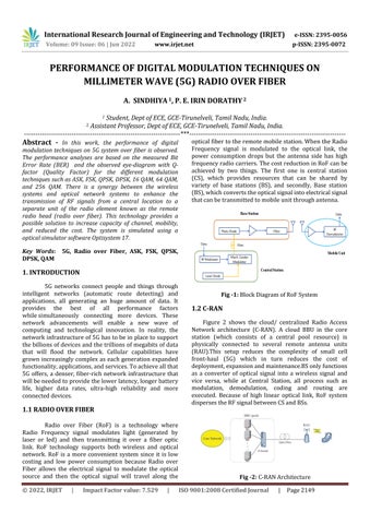
optical fiber to the remote mobile station. When the Radio Frequency signal is modulated to the optical link, the power consumption drops but the antenna side has high frequency radio carriers. The cost reduction in RoF can be achieved by two things. The first one is central station (CS), which provides resources that can be shared by variety of base stations (BS), and secondly, Base station (BS), which converts the optical signal into electrical signal that can be transmitted to mobile unit through antenna.
5G, Radio over Fiber, ASK, FSK, QPSK,
1. INTRODUCTION 5G networks connect people and things through intelligent networks (automatic route detecting) and applications, all generating an huge amount of data. It provides the best of all performance factors while simultaneously connecting more devices. These network advancements will enable a new wave of computing and technological innovation. In reality, the network infrastructure of 5G has to be in place to support the billions of devices and the trillions of megabits of data that will flood the network. Cellular capabilities have grown increasingly complex as each generation expanded functionality, applications, and services. To achieve all that 5G offers, a denser, fiber-rich network infrastructure that will be needed to provide the lower latency, longer battery life, higher data rates, ultra-high reliability and more connected devices.
1.1 RADIO OVER FIBER Radio over Fiber (RoF) is a technology where Radio Frequency signal modulates light (generated by laser or led) and then transmitting it over a fiber optic link. RoF technology supports both wireless and optical network. RoF is a more convenient system since it is low costing and low power consumption because Radio over Fiber allows the electrical signal to modulate the optical source and then the optical signal will travel along the © 2022, IRJET
|
Impact Factor value: 7.529
|
Fig -1: Block Diagram of RoF System
1.2 C-RAN Figure 2 shows the cloud/ centralized Radio Access Network architecture (C-RAN). A cloud BBU in the core station (which consists of a central pool resource) is physically connected to several remote antenna units (RAU).This setup reduces the complexity of small cell front-haul (5G) which in turn reduces the cost of deployment, expansion and maintenance.BS only functions as a converter of optical signal into a wireless signal and vice versa, while at Central Station, all process such as modulation, demodulation, coding and routing are executed. Because of high linear optical link, RoF system disperses the RF signal between CS and BSs.
Fig -2: C-RAN Architecture ISO 9001:2008 Certified Journal
|
Page 2149
International Research Journal of Engineering and Technology (IRJET)
e-ISSN: 2395-0056
Volume: 09 Issue: 06 | Jun 2022
p-ISSN: 2395-0072
www.irjet.net
2. SYSTEM DESIGN
3.2 Q-FACTOR
The proposed system consists of a transmitter (Tx) and a receiver (Rx) end. At the transmitter stage, the input data signal at the bit rate of 10 Gbps is modulated using the various modulation methods by a PseudoRandom Bit Sequence (PRBS) generator for 60 GHz and 5 GHz. The incoming signal is passed through the Optical Band Pass Bessel Filter (OBPF) possess cut off frequency of 10 GHz for modulating an optical carrier of frequency 193.1 THz use a Mach-Zehnder Modulator (MZM). The Mach-Zehnder modulator is a high-speed external modulator for modulating the intensity or phase of the light source. The modulated signal is passed through a single-mode fiber mostly used at 1310 nm and 1550 nm and is amplified using an optical amplifier. At the Rx, the amplified optical signal is fed to OBPF to filter the upper sideband (USB) of the optical signal which is subsequently applied to the PIN photo-detector. This photo-detector demodulates the filtered optical signal and converts it directly into a baseband signal that is an electrical signal. The output of the Low Pass Filter (LPF) is seen using a BER analyzer and an eye-diagram analyzer. Besides, the same amount of data that was transmitted is received at the output of the LPF.
The value of Q factor depends on the value of Bit Error Rate. The Q-factor is a function of the OSNR (Signal to Noise Ratio) that provides a qualitative description of the receiver performance. It suggests the minimum SNR is essential to obtain a certain BER for a given signal. Figure 4 shows the graph that indicates the relationship between the value of BER and Q factor. It is seen that the value of Q factor increases when the BER decreases. The Q factor value for 10−9 of BER is approximately 6.
Fig -4: BER vs. Q-factor
3.3 EYE PATTERN It is an oscilloscope display of a digital signal received from a receiver, that is repetitively sampled and applied to the vertical input and the data rate is used to trigger the horizontal sweep. An open eye pattern indicates to the minimal signal distortion and the close eye pattern indicates distortion of the signal due to inter-symbol interference (ISI) and noise.
4. RESULT
Fig -3: ASK based RoF system design
3. PERFORMANCE METRICS To determine the quality of receiver in RoF, the bit error rate (BER), eye opening of the eye pattern and Qfactor value is measured and analyzed.
3.1 BIT ERROR RATE It is the number of received bits of an input data stream over a channel that has been changed due to noise, interference and distortion orbit synchronization errors. According to International Telecommunication Union (ITU), the minimum value of BER of RoF must be below than 10−9. © 2022, IRJET
|
Impact Factor value: 7.529
|
The result shows that only the QPSK predicts the best values of BER across the varying optical fiber line which can be associated with sparsely spaced points on the constellation. However, as the length of the optical fiber increases, the BER value degrades in consequences to the losses per km along the optical fiber line. It is then observed that the values obtained for the 1550 nm are better than the values obtained at 1310 nm. Higher-order modulations allow sending of more bits per symbol because of denser points within the constellation amounting to higher throughputs and better spectral efficiencies suited for 5G systems; trades-off exists because the higher modulation schemes are susceptibility to noise and errors.
ISO 9001:2008 Certified Journal
|
Page 2150
International Research Journal of Engineering and Technology (IRJET)
e-ISSN: 2395-0056
Volume: 09 Issue: 06 | Jun 2022
p-ISSN: 2395-0072
www.irjet.net
5. CONCLUSION This suggests that the core station should be around 5 km from the base station for effective and increased throughput. The worst value of BER in correspondence with the lowest value of Q-factor at 256 QAM for 1310 nm pointing out the effect of wavelength in an optical line in the transmission system.
REFERENCES Fig -5: Min BER of Different Modulation Techniques (1310nm)
[1] Tesanovic M and Nekovee M 2015 mmWave-based mobile access for 5G: key challenges and projected standards and regulatory roadmap Global Communication Conf. (California,USA) pp 1-6 [2] Beas J,Castañón G,Orozco F, Aldaya I,Zavala A A and Campuzano G 2015 Knowledge-based framework for the design of millimeter-wave (60 GHz) radio over fibre land networks vol 30 (Photonic Network Communications) pp 234-60R. Nicole, “Title of paper with only first word capitalized,” J. Name Stand. Abbrev., in press. [3] Namita K, Garg A K 2017 Performance analysis of Radio over Fibre system using Direct and External Modulation Schemes Vol 8 (International Journal of Scientific & Engineering Research) p 174
Chart -1: Modulation Techniques (1310nm)
[4] Kamaljit Singh Bhatiaa, Sandeep Singh “Performance Analysis of RoF link using Mach-Zehnder Modulator and its parameters ”An International Journal of Engineering Sciences, Special Issue ICTMS-15, 29-30 December 2015 ISSN: 2229-6913 (Print), ISSN: 23200332 [5] Lisawati S, Khadijah I 2017 Receiver Performance Improvement in Radio over Fibre Network Transmission (Rastislav roka intechopen) pp 160-3
Fig -6: Min BER of Different Modulation Techniques (1550nm)
[6] Pradeep R and Vijayakumar N, “Performance Analysis of RoF link using Mach-Zehnder Modulator in radio over fiber systems ” International Journal of Advanced Research in Engineering and Technology (IJARET). ISSN Print: 0976-6480 and ISSN Online: 0976-6499 Volume 7, Issue 5, September-October 2016, pp. 45– 52 [7] Jincy John and Sreenesh Shashidharan, “Design and Simulation of a Radio over Fiber System and its Performance Analysis.” Optical Networking Technologies and Data Security - OPNTDS 2012IEEE.
Chart -2: Modulation Techniques (1550nm) © 2022, IRJET
|
Impact Factor value: 7.529
|
ISO 9001:2008 Certified Journal
|
Page 2151