International Research Journal of Engineering and Technology (IRJET) e ISSN: 2395 0056

Volume: 09 Issue: 06 | Jan 2022 www.irjet.net p ISSN: 2395 0072
International Research Journal of Engineering and Technology (IRJET) e ISSN: 2395 0056
Volume: 09 Issue: 06 | Jan 2022 www.irjet.net p ISSN: 2395 0072
Mayur Bidwe1, Shrinit Lambodari2
1,2 Student, Dept. of Mechanical Engineering, KBTCOE, Nashik, Maharashtra, India ***
Abstract - All terrain vehicle is famously used for various purposes. The design of the chassis frame for the use of all terrain vehicles (ATV) is presented. In designing the chassis frame, a correct design method was employed. Finite Element Analysis (FEA) was utilized to determine the maximum stress and displacement of the frame when a particular load is applied to it. The chassis is the component in charge of supporting all other vehicle subsystems with the plus of taking care of the driver's safety. It must be strong and durable taking always into account the weight distribution for better performance. The fabrication of the frame is done by us and the fabricated frame will be used as the main part of a project in which a complete ATV will be developed.
Key Words: Chassis Frame1, All Terrain Vehicle2, Finite Element Analysis3, Safety4
Asperthename,ATVisintendedtorunandmaneuveron totallydifferentterrains,orinalternativewords,weareable to say that associate ATV is intended for the off roading purpose. In off roading, we have a tendency to encounter variedloadthatisfinallytransmittedtotheframe.Theframe is the most vital part of the auto as all the mountings and assembliesaredoneontheframeitself,thereforeitbecomes necessaryfortheassociateATVframetosustaineachstatic anddynamicmasses.duringthisstudy,we'vegottoarguea correctmethodologyforplanningandanalyzingtheframe beforetheATVistestedonvigorousterrainsandconditions.
Varioussortsofframesareusedarerelyinguponthekind ofloadingthatthey'regoingtobear,forinstance,aladder frameisemployedinsignificantindustrialvehicleswherever theloadshouldbetransferredfromoneplacetoadifferent, equally there are alternative varieties like monocoque chassis, ULSAB, cannular area frame, etc. Among this cannulararea,theframeisonethatwe'vegotthought about forplanningourATVasaresultitprovidesmulti directional impactsafetyfurthermoreandissimplerinfabrication.
D.Nagarjuna et al. [1] havementionedthevariousvogue problems taken into consideration for building a perfect ATV. The loading analysis has been done considering the variousparameters.Overallthisreporthasprohibitedvaried loadanalysisonchassisandoptimizationhasbeenachieved byreducingtheloadofthechassisframe.Theusageoffinite
partanalysiswasvaluabletotheplanningandanalysisofthe frame for all items of a ground vehicle. Bobbing up with analysismaybehard0.5to carryon toas massesof tests square measure needed to be conducted with heaps of constraints.Thechassiswasdesignedsothatthevehiclecan set about all kinds of tons and is capable of moving on terrainslikeroughareas
Hirak Patel et al. [2] has designed the truck chassis analyticallyandalsotheweightimprovementiscompleted by sensitivity analysis. In sensitivity analysis, completely differentcrosssectionareaunitsareusedforstressanalysis andwerealizeaweightreductionwithinthetruckchassis the strain and deformation are compared for the various crosssections.
William B. Riley et al. [3] have mentioned a spread of problemsassociatedwithframeandchassisstyle,aneasy mathematical model was developed for examination the structural stiffness to realize insight into the correct style target for the vehicle structure. The model was made on ANSYSandafewexperimentalstrategieswereconferredthe bestcapturetheloadelementsandsuspensioncontributors. The various road masses and deformation modes were thought about further as generic style targets supported expertise and strain gauged suspension links. An easy mathematical model was developed for examination the structural stiffness to the suspension stiffness to realize insight into correct style targets for the vehicle structure. These charts additionally aid in visualizing the trade off between stiffness and weight the designer should create. With these stiffness targets in mind, a finite component modelwasmade.
Upendra S. Gupta et al. [4] elaborate description of the planning concerns, static and dynamic analysis associated mathematicalinformationconcernedwithinthestyleofan ATV vehicle. The main focus has been arranged on the simplicity of style, high performance, straight forward maintenance,and,safetyataffordablecost.Theplanningand developmentcomprisematerialchoice,chassis,framestyle, crosssectiondetermination,decidingstrengthneedsofroll cage stress analysis, and, simultaneous checking the ATV againstfailure.
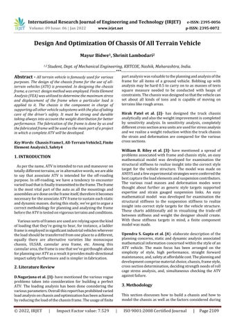
This section discusses how to build a chassis and how to modelthechassisaswellasthefactorsconsideredduring
International Research Journal of Engineering and Technology (IRJET) e ISSN: 2395 0056
Volume: 09 Issue: 06 | Jan 2022 www.irjet.net p ISSN: 2395 0072
the design process. In the field of safety and esthetics, we built the roll cage. They are the two variables that matter mosttous,andtheyarethereforeofgreatimportance.CAD modelingdesignofanycomponentcomprisesthreemajor principles, Optimization, Safety, and Comfort. The main features of chassis are Nodal geometry utilization, Less Weight, Driver Comfort Appropriate Triangulation The major factors considered in designing an ergonomically suitedrollcagewere,Seatlocation,Seatinclination,Steering, wheellocation,SteeringColumnlocation,Designofthefoot box area. Mesh size is calculated by checking the mesh independency.Itmeansthattherewillbenegligiblechanges intheaccuracyofresultsonfurtherreductioninmeshsize. Theanalysiswillbecarriedoutusingprogressivelyreducing elemental sizes. The elemental size having a consecutive stresserroroflessthan5%isconsideredtheoptimumsize ofthemesh.Itmeansthatanyfurtherdecreaseinsizewill onlynegligiblyincreasetheaccuracyoftheresults.
Magnetization Preheatingofthespecimeni.e.tubesofChromolysteel4130 wasdonebeforebendingoperationsothatthecomponent wouldbefreefromresidualstresses&deformationwould beavoided. Thepreheatingte minutes.
International Research Journal of Engineering and Technology (IRJET) e ISSN: 2395 0056
Volume: 09 Issue: 06 | Jan 2022 www.irjet.net p ISSN: 2395 0072
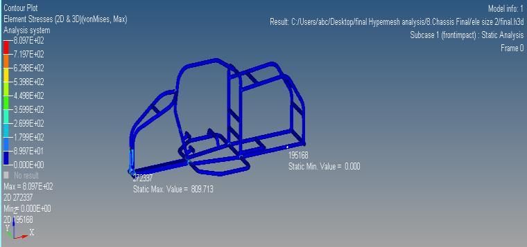
5.1 FORCE CALCULATION FOR ANALYSIS:
F=W/D
W=½MV^2 =½*200*16.66^2
= 27755.55N M D=1.66M, F=27755.55/1.66 =16720.2N
5.2 WELD THICKNESS CALCULATION:-
1. FMAX= 16720.2N
2. PermissibleshearstressforMIGweldingis0.3syt =0.3*460=138MP
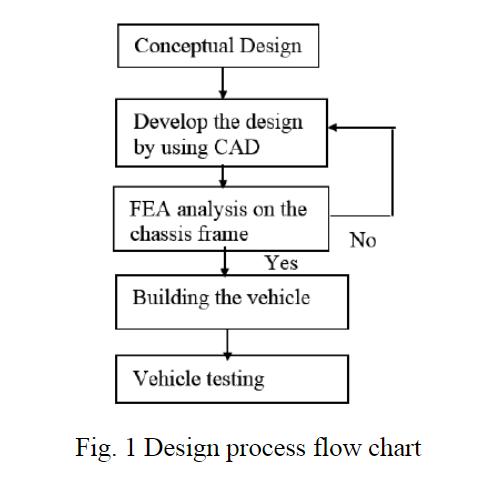
Thus from the above studies, we selected choromoly4130asourchassismaterialasithasvariousplus pointsoverotherssuchasreasonablecost,wideavailability, easilyweldable,lowcost,andcanhandleallthestressesas peranalysisconductedonit.
3. Weldthicknessidgivenas, Per.Shearstress= F/tl, Where, t=weldthickness l=lengthofweld=80mm, Now, 138=16720/t*80 t=1.52mm
Step 1: The rear hubs were constrained in all degrees of freedombymountingthemtightlytotheadapterplatevia theblocktotheI beamsection.Theadapterplatehadbeen weldedfirmlytotheblock.
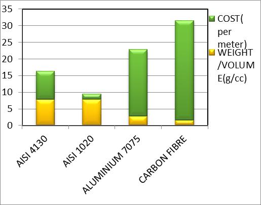
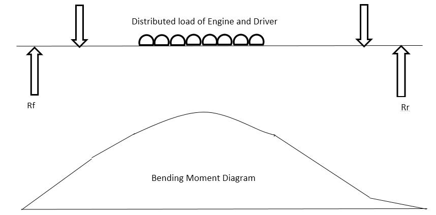
For a maximum bending moment, all the loads at different points were considered. Loads on the chassis at different locations include 1. Steering housing, column, bearings,etc.of8kgat200mmfromchassisfront.2.Engine, driver weight, seat, fuel tank, mounts, etc. of 120kg at 524mm(524to955mm)fromchassisfront.3.Transmission, suspensionassemblies,etc.about12kgat1350fromchassis front.Bycalculatingthemaximumbendingmomentofabout 535.40Nm at 801.0mm from the chassis front. This calculated moment will be sustained by two members so each member will carry 267.7Nm which is less than 487.5Nm (bending moment for chromoyl 4130). So our designissafe.
Step 2: Front mounting points were constrained in all degreesoffreedomexceptonerotationaldegreeoffreedom alongtheX axis.Forthat,arollerhadbeenmadeinthefront system.
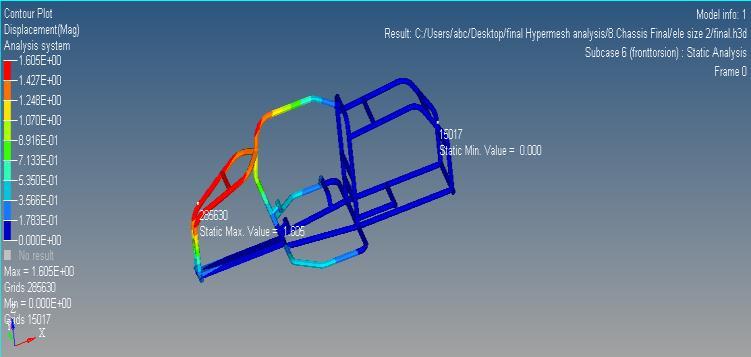
Step3:Thefronttorsionstandsattachthefronthubsofthe chassis to an I beam. The axis of rotation of the beam is paralleltothelongitudinalaxisofthechassis.
Step4:Weightsarenowplacedontheendsofthepivoting beamalternatively,causingittopivot.Theseraiseonestand andlowertheotherbyanequalamountwhilekeepingthe rear stands fixed. The moment or torque applied is the amountofweightmultipliedbyitsdistancefromthecenter ofrotation.
2022, IRJET | Impact Factor value: 7.529 | ISO 9001:2008 Certified Journal
International Research Journal of Engineering and Technology (IRJET) e ISSN: 2395 0056
Volume: 09 Issue: 06 | Jan 2022 www.irjet.net p ISSN: 2395 0072
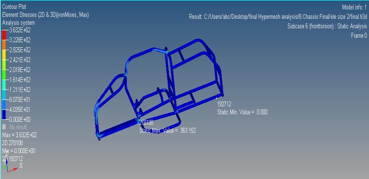
Step 5: The twist of the frame is found by measuring the verticaldisplacementofthepivotingI beam.
Step6:Inthis experiment,a dial indicatorwasusedsince proofofconceptandnotaccuracywasthegoal.Threedial indicatorswereusedinthesuspensionmountingpointsand onedialindicatorwasusedintheenginecompartment.
(Note:Atfirstreadingsweretakenwiththeenginemounted on the chassis and later the engine was removed and the readings were taken again. Mobiles were mounted at the rearandfrontsectionstocalculatetheangleoftwist.)
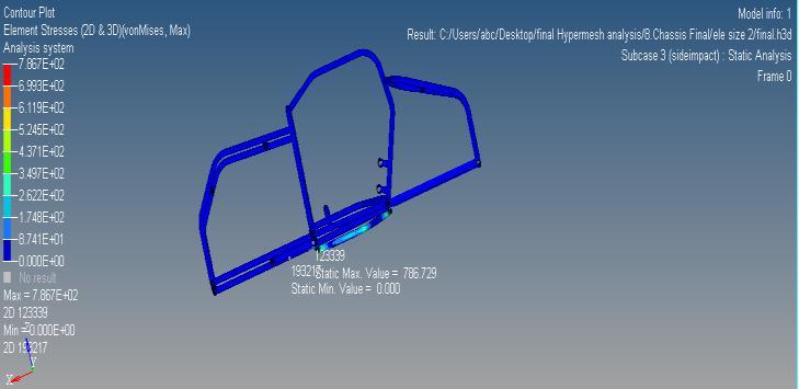
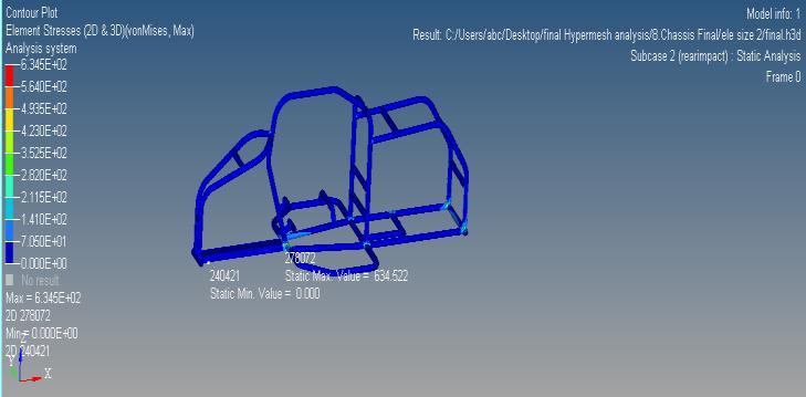
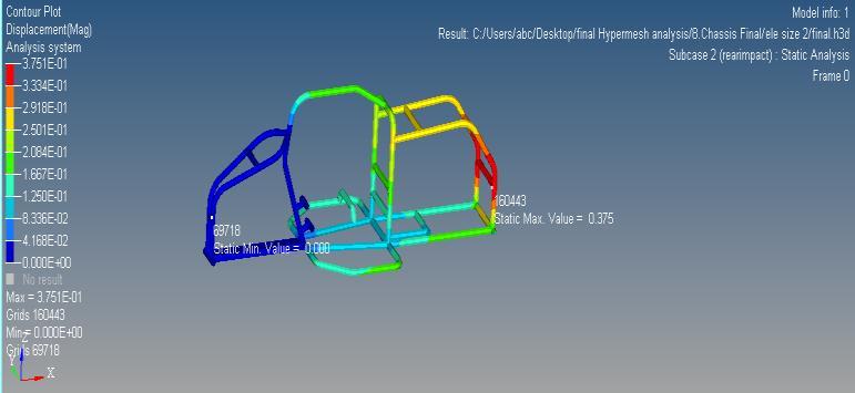
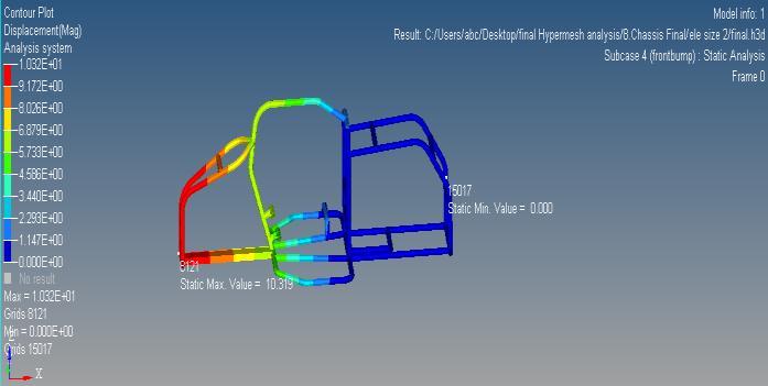
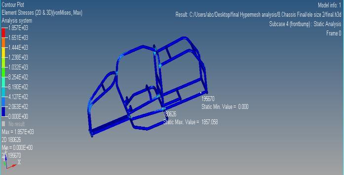
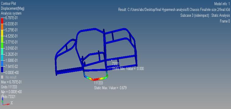
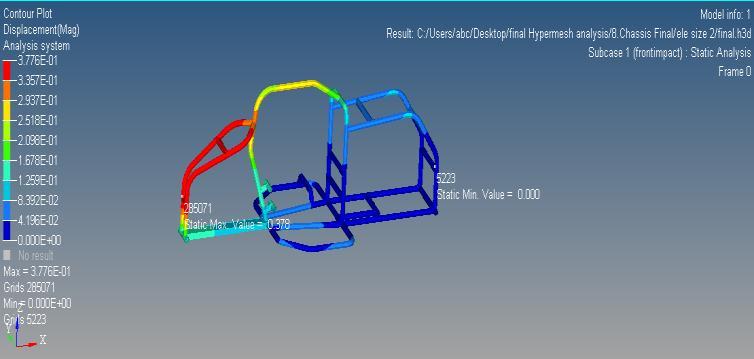
Thisdocumentsuccessfullydemonstratesthechassisframe constructionmethodforATVuse.Thefiniteelementanalysis (FEA)resultsshowthatthedesignedchassiscanhandlethe givenrealizedload.Sincetheevaluationresultsarewithin the usual range, the chassis is manufactured. This chassis willlaterbeusedasthemainpartoftheATVdesignedfor academicpurposes.
[1]D.Nagarjuna;J.M.Farooq;A.S.N. Saiteja;P.S.S.Teja, Optimization Of Chassis of an All terrain Vehicle, International Journal of Innovative Technology and ExploringEngineering,Vol2,(2)(2013)55 57.
[2] G.H.Hohl, Military terrain vehicles, Journal of Terra mechanics,Vol.44,(2007)23 34.
International Research Journal of Engineering and Technology (IRJET) e ISSN: 2395 0056 Volume: 09 Issue: 06 | Jan 2022 www.irjet.net p ISSN: 2395 0072
[3]S.Milosavljevic,F.Bergman;B.Rehn,A.B.Carman,All terrain vehicle use in agricultureExposure to whole body vibrationandmechanicalshock,Appliedergonomics,Vol41, (2010)530 535.
[4] K. Chaudhari; A. Joshi; R. Kunte; K. Nair, Design And Development of Roll Cage For An All Terrain Vehicle, InternationalJournalofTheoreticalandAppliedResearchin MechanicalEngineering,Vol.4,(2013)49 54.
[5] F. A. Munir; M. I. M. Azmi, M. A. Salim; M. R. Zin; M. Z. Hassan,PreliminaryDesignofCarbonCompositeFacingfor DryClutchDisc ofMini Agricultural Tractor,International Review of Mechanical Engineering (IREME), Vol. 5, n. 4 (2011)577 580.
[6]D Sh iv v,“D ig i g AllT i V hicl (ATV)”, InternationalJournalofScientificandResearchPublications, Vol4,Issue12,December2014,pp1 16.
2022, IRJET | Impact Factor value: 7.529 | ISO 9001:2008 Certified Journal