International Research Journal of Engineering and Technology (IRJET) e ISSN:2395 0056

Volume: 09 Issue: 06 | June 2022 www.irjet.net p ISSN:2395 0072
International Research Journal of Engineering and Technology (IRJET) e ISSN:2395 0056
Volume: 09 Issue: 06 | June 2022 www.irjet.net p ISSN:2395 0072
Mr. Charakpalle Chandrashekhar V.1 , Prof. Kariappa M S 2
1Department of Civil Engineering, M S Bidve Engineering College Latur
2Assistant Professor, Department of Civil Engineering, M S Bidve Engineering College Latur ***
ABSTRACT:
The ancient Romans used concrete and poured it into moulds to construct a sophisticated network of aqueducts, culverts, and tunnels. Pre cast technology is now used in a range of architectural and structural applications, from individual components to full building systems. When an earthquake strikes a reinforced concrete structure, the beam column junctions are critical zones. Due to the huge stresses and moments generated by significant ground shaking, concrete in the joint location cracks diagonally and crushes. Thus, for the design of beam column junctions, extremely ductile materials are necessary. There are three types of beam column joints: interior, exterior, and corner. The purpose of this research is to analyse RCC buildings for dead loads, live loads, and earthquake loads in order to identify critical joints and to analyse critical joints in ANSYS for axial forces, shear forces, and bending moments, as well as the impact of utilising a geopolymer layer.
Keywords: Beam Column Joint, Geo-polymer, Non Linear Analysis, ANSYS, Staad Pro
The beam column joints are the crucial zones when a reinforced concrete building experiences an earthquake. The large forces and moments produced during severe groundshakingleadstodiagonalcrackingandcrushingof concreteinthejointregion. Thus,highlyductilematerials are required for the design of beam column joints. Beam column joints can be classified into interior, exterior and corner joints. The longitudinal bars of a beam need to be anchored into the column to ensure a proper grip, especially in the case of exterior beam column joints. The capacityofthebeaminanexteriorjointisgovernedbythe momentcreatedbyshearcapacityofbeamratherthanits flexuralcapacity.
Geopolymerconcreteisearningattentionnowadaysforits low CO₂ emissions and as a sustainable alternative to ordinary portland cement. The term "geopolymers" was first coined by Joseph Davidovits in 1978 to classify a Three Dimensional (3D) polymeric network of alumino silicate binders. An alkaline activator solution is used in the geopolymerisation reaction which acts as a catalytic liquidsystem.GPCcanbecuredunderambientconditions thus reducing the usage of water compared to conventional curing methods. Heat cured specimens gained strength immediately but more compressive strengthwasobtainedforspecimenswhichwerecuredin ambient conditions. A combination of Sodium Silicate (Na₂SiO3) and Sodium Hydroxide (NaOH) solutions are
commonlyusedintheproductionofGeopolymerConcrete (GPC). The compressive strength of GPC specimens increased with the increase in concentration of NaOH so GGBS and fly ash are the most commonly used source materialsintheproductionofGPC.TheusageofGGBSand dolomite together as binders is a comparatively new methodintheproductionofGPC.GroundGranulatedBlast Furnace Slag (GGBS) is a by product released from the blast furnaces of the iron industry. It is evident from the experimental studies that inclusion of GGBS enhances concrete workability, durability, density, compressive strength and reduces the setting time. Dolomite is a by product from rock crushing industry and contains higher CaO content which can significantly improve the strength of concrete . However, it has never been used in the production of GPC. Hence, it is expected that inclusion of dolomite for preparing geopolymer concrete can yield some better results and reduce its disposal problem as well.
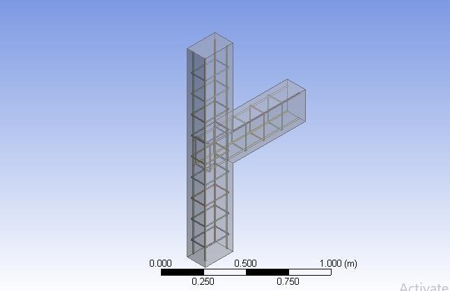
The present study aims to evaluate the behaviour and performance of steel fibre reinforced dolomite GGBS geopolymer concrete beam column joints under mono tonic loading using finite element methods. Beam column joints are modelled by using the Finite Element Method [FEM] ANSYS to evaluate the response of joints under monotonic loading. Non linear analysis has been carried out to study the behaviour of the beam column joint models under gradually increasing monotonic load applied at the bottom of the free end of the beam. The crack/crush patterns, deflections and stresses at various pointswereevaluatedforsteelfiberreinforcedGPC.lution
International Research Journal of Engineering and Technology (IRJET) e ISSN:2395 0056
Volume: 09 Issue: 06 | June 2022 www.irjet.net p ISSN:2395 0072
ratio of Na₂SiO, to NaOH solutions, mixing time, curing timeandcuringtemperature.
The objectives of this study are specifically given as following.
1. ToperformanalysisofRCCbuildingforDeadload, live load and Earthquake load to identify Critical joint.
2. To Perform analysis of critical joint for axial forces, shear forces and Bending moment in ANSYSanditseffectusingGeopolymerlayer
3. Comparativeanalysisof beamcolumn connection using Geopolymer with RCC beam column connection for bending stresses, shear stresses, principalstressesandDeflection
4. ToinvestigatetheimportantaspectsofGFRPbars in geopolymer concrete, the flexural and shear behaviour of geopolymer concrete beams longitudinally and transversely reinforced with GFRP bars and stirrups, respectively, and the compression behaviour of geopolymer concrete columnsinternallyreinforcedwithGFRPbarsand ties.
2.1 June, M. (2017).
Beam and column where intersects is called as joint or junction. The different types of joints are classified as corner joint, exterior joint, interior joint etc. on beam column joint applying quasi static loading on cantilever endofthe beamandstudy ofvariousparametersastobe find out on corner and exterior beam column joint. The focus of our project is T shaped concrete frame connection. There was minimum damage on the concrete column and joint panel zone. For a specimen with strong beams weakcolumns,therewaslocalbucklingfractureon steel tube above and below the joint panel zone. It was found that both axial forces and beam to column linear stiffness ratio had impacts on joint capacity and ductility behavior of the specimens. However, addressed beam column joints of substandard RC frames with weak columns, poor anchorage of longitudinal beam bars and insufficient transverse reinforcement. The behavior of exterior beam column joint is different than the corner beamcolumnjoint.
2.2
T., & Piruntha, M. (2018).
FlyAshbasedgeopolymerconcreteiscritical tostudythe fulfillment of a new material in various packages for its use in production of structures and additionally the eco pleasant concrete. For implement this recent material distribution of longitudinal and lateral metal, tie spacing, andtheextentofaxialload.ModelcreatedbyANSYSwith 9 feet long columns. Loading will be increased gradually 10KN maximum deflection at 0.051mm at 50KN. The specimens have been subjected to an axial load underperforming FE analysis of RCC column by using ANSYSsoftware. The result showsthe appropriate way of using the scientific technique to geopolymer concrete columnssubjectedtomixedaxialloadandbiaxialbending.
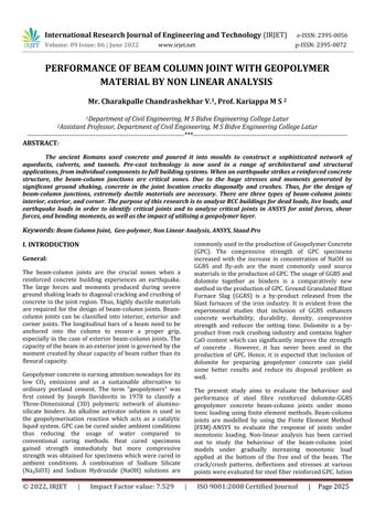
Fig 1: Flowchart
Dynamicanalysisusingthetimehistoryanalysiscalculates the building responses at discrete time steps using discredited record of synthetic time history as base motion. If three or more time history analyses are performed,onlythemaximumresponsesoftheparameter of interest are selected. Time history analysis is the study ofthedynamicresponseofthestructureateveryaddition
International Research Journal of Engineering and Technology (IRJET) e ISSN:2395 0056
Volume: 09 Issue: 06 | June 2022 www.irjet.net p ISSN:2395 0072
of time, when its base is exposed to a particular ground motion. Static techniques are applicable when higher mode effects are not important. This is for the most part validforshort,regularstructures.Thus,fortallstructures, structures with torsional asymmetries, or no orthogonal frameworks,adynamicmethodisneeded.
It was the first major earthquake that has been recorded by a strong motion seismograph located next to a fault rupture. The earthquake was characterized as a typical moderate sized destructive event with a complex energy release signature. It was the strongest recorded earthquake to hit the Imperial Valley, and caused widespreaddamage.
AG+9RCCCommercialbuildingisconsidered.
Plandimensions:12mx12m
Locationconsidered:Zone III
SoilTypeconsidered:HardStrata.
GeneralDataofBuilding:
•Gradeofconcrete:M25
•Gradeofsteelconsidered:Fe250,Fe500
•Liveloadonroof:2KN/m2(Nilforearthquake)
•Liveloadonfloors:4KN/m2
•Rooffinish:1.0KN/m2
•Floorfinish:1.0KN/m2
•Brickwallinlongitudinaldirection:240mmthick
•Brickwallintransversedirection:140mmthick
•Beaminlongitudinaldirection:230X350mm
•Beamintransversedirection:230X350mm
•Columnsize:300X750mm
•Densityofconcrete:25KN/m3
•Densityofbrickwallincludingplaster:20KN/m3
•Plinthbeam(PB1):350X270mm
•Plinthbeam(PB2):270X300mm
Introduction:
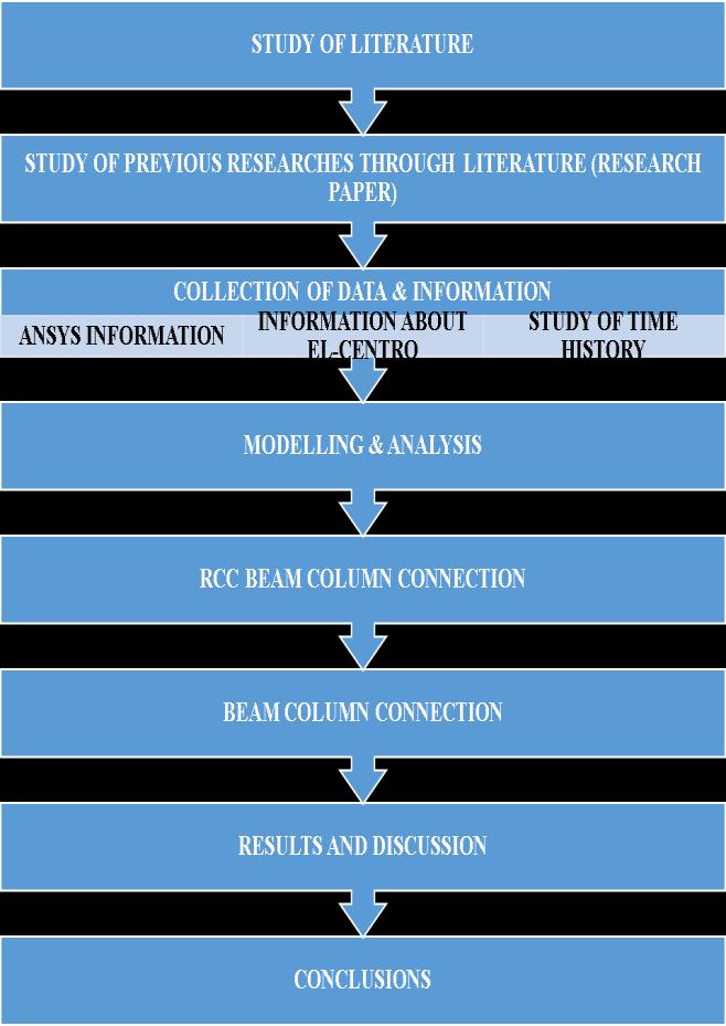
Inordertoidentifythecriticalbeamwehaveconsidereda G+7 RCC Commercial building for analysis and design purpose in STAAD pro software which is analyzed for 1.5(DL+LL) load combination and the beam with maximum bending moment is identified for considered building the details of the building considered are as follows:
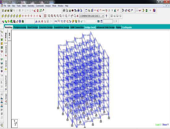
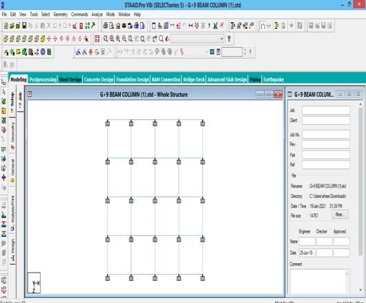
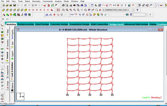
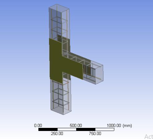
Fig 2: G + 9 Frame Storied Building And Having Loads Can Apply On Beams And Columns
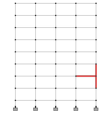
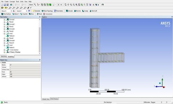
MODELLING IN STADD PRO
Fig 3: Plan View
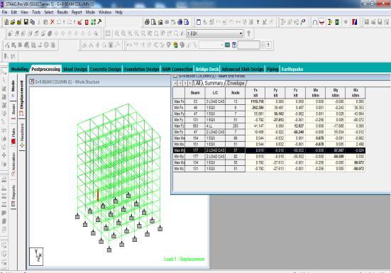
Fig 4: Shear Force Of Beams In STAAD Pro
International Research Journal of Engineering and Technology (IRJET) e ISSN:2395 0056
Volume: 09 Issue: 06 | June 2022 www.irjet.net p ISSN:2395 0072
The definition of the proposed numerical model was madebyusingfiniteelementsavailableintheANSYScode default library. SOLID186 is a higher order 3 D 20 node solid element that exhibits quadratic displacement behavior.Theelementisdefinedby20nodeshavingthree degreesoffreedompernode:translationsinthenodalx,y, and z directions. The element supports plasticity, hyperelasticity, creep, stress stiffening, large deflection, andlargestraincapabilities.Italsohasmixedformulation capability for simulating deformations of nearly incompressible elastoplastic materials, and fully incompressible hyperelastic materials. The geometrical representationofisshowinSOLID186fig22.
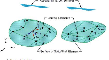
This SOLID186 3 D 20 node homogenous/layered structural solid were adopted to discretize the concrete slab, which are also able to simulate cracking behavior of the concrete under tension (in three orthogonal directions) and crushing in compression, to evaluate the material non linearity and also to enable the inclusion of reinforcement (reinforcement bars scattered in the concreteregion).TheelementSHELL43isdefinedbyfour nodes having six degrees of freedom at each node. The
deformation shapes are linear in both in plane directions. The element allows for plasticity, creep, stress stiffening, large deflections, and large strain capabilities The representationofthesteelsectionwasmadebytheSHELL 43 elements, which allow for the consideration of non linearity of the material and show linear deformation on theplaneinwhichitispresent.Themodelingoftheshear connectors was done by the BEAM 189 elements, which allow for the configuration of the cross section, enable consideration of the non linearity of the material and includebendingstressesasshowninfig3.5.CONTA174is usedtorepresentcontactandslidingbetween3 D"target" surfaces (TARGE170) and a deformable surface, defined by this element. The element is applicable to 3 D structural and coupled field contact analyses. The geometrical representation of CONTA174 is show in fig 3.2. Contact pairs couple general axisymmetric elements with standard 3 D elements. A node to surface contact element represents contact between two surfaces by specifying one surface as a group of nodes. The geometrical representation of is show in TARGET 170 fig 19.
The TARGET 170 and C0NTA 174 elements were used to represent the contact slab beam interface. These elements are able to simulate the existence of pressure between them when there is contact, and separation between them when there is not. The two material contacts also take into account friction and cohesion betweentheparties.
Fig. 7 CONTA 174
Fig 8: Shell 43
International Research Journal of Engineering and Technology (IRJET) e ISSN:2395 0056
Volume: 09 Issue: 06 | June 2022 www.irjet.net p ISSN:2395 0072
Sr.No. Material Property Value
Yieldstress fsy (MPa) 265
Ultimate strength fsu(MPa) 410
1 Structural steel
Young’s modulus Es(MPa) 205×103
Poisson’sratioµ 0.3
Ultimatetensilestrain et 0.25
Yieldstress fsy (MPa) 250
Ultimate strength fsu (MPa) 350
2 Reinforcing bar
Young’s modulus Es(MPa) 200×103
Poisson’sratioµ 0.3
Ultimatetensilestraine t 0.25
Compressive strength fsc(MPa) 42.5
Tensile strength fsy(MPa) 3.553
that is extensively used across the globe. It complies with over 90 international design regulations for steel, concrete, wood, and aluminium. It may use a variety of analyticaltechniques,rangingfromclassicalstaticanalysis tomorecontemporarytechniquessuchasp deltaanalysis, geometric non linear analysis, pushover analysis (Static NonLinearAnalysis),or bucklinganalysis.Additionally,it maymakeuseofavarietyofdynamicanalytictechniques, ranging from time history analysis to response spectrum analysis.Theresponsespectrumanalysiscapabilityworks withbothuser definedandavarietyofinternationalcode defined spectra. Additionally, STAAD Pro is compatible with products such as RAM Connection, Auto PIPE, and SACS,aswell asa varietyof other engineeringdesign and analysissoftware,whichfacilitatescooperationacrossthe manydisciplinesinvolvedinaproject.STAADmaybeused to analyse and design a wide variety of structural structures, ranging from plants and buildings to towers, tunnels, metro stations, and water/wastewater treatment facilities.
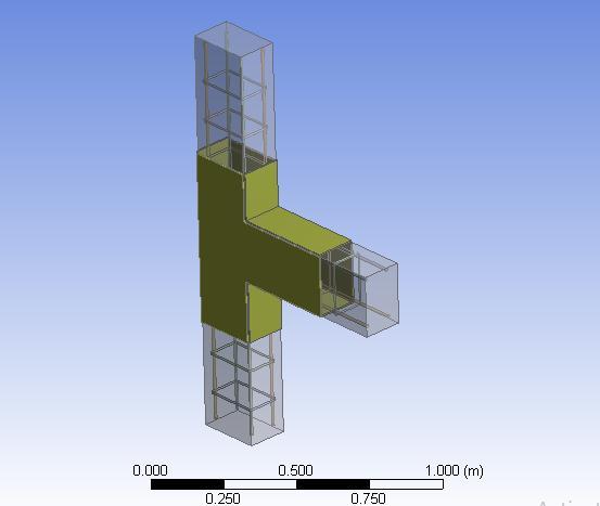
4.4 ANSYS model:
Details for ANSYS Models for Precast and RCC
ColumnSize 300x750mm
3 Concrete
Young’s modulus Ec(MPa) 32920
Poisson’sratioµ 0.15
Ultimate compressive straines 0.045
Yieldstress fsy (MPa) 435
Tensile strength fsu (MPa) 530
ReinforcementforColumn 12 16No BeamSize 230x450mm
Reinforcement for Beam Top 12 2, Bottom 12 2, Shear 10 @120C/C
TotalMaximumLoad 1824KN RCCModel
4 Duplex steel
Young’s modulus Es(MPa) 200×103
Poisson’sratioµ 0.31 density 7.8
STAADor(STAADPro)isa structural analysisanddesign software tool that was created in 1997 by Research Engineers International. Bentley Systems acquired ResearchEngineersInternationalinlate2005.STAADPro is a structural analysis and design software application
Fig 9: No wrapping model
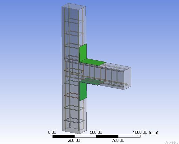
Analysis of Beam Column joint by using ANSYS Software: Modeling of beam column joints in ANSYS Software
International Research Journal of Engineering and Technology (IRJET) e ISSN:2395 0056
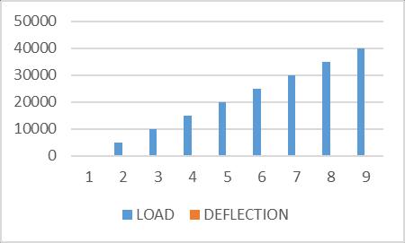
LOAD DEFLECTION STRESS STRAIN
0 0 0 0
5000 4.39116 186.208 0.002361
10000 5.32059 754.676 0.002807 15000 6.25002 758.793 0.003254 20000 7.17945 762.9215 0.0037 25000 8.10888 767.05 0.004146 30000 9.03831 771.1785 0.004593 35000 9.96774 775.307 0.005039 40000 10.89717 779.4355 0.005485
Load vs Deflection For T Shape without Geo polymer
load vs Deflection For T Shape with Geo polymer GS1
Aswecanseein thegraph, deflection isincreasing asper loadsareincreasing.Alsostressandstrainandincreasing whenloadsareincreasing.
Analysis of Geo polymer Specimens
For T Shape: Geo polymer Specimen 1 (GS1)
LOAD DEFLECTION STRESS STRAIN
0 0 0 0
5000 1.2002 68.617 0.002053
10000 1.1786 99.863 0.002441 15000 2.1618 131.5 0.002829
20000 3.1504 163.137 0.003217 25000 4.139 194.774 0.003606
30000 5.1276 226.411 0.003994 35000 6.1162 258.048 0.004382 40000 7.1048 289.685 0.00477
Aswecanseein thegraph, deflection isincreasing asper loads areincreasing.Alsostressandstrainandincreasing whenloadsareincreasing.
Analysis of Geo polymer Specimens
For T Shape: Geo polymer Specimen 2 (GS2)
LOAD DEFLECTION STRESS STRAIN 0 0 0 0
5000 2.036 154.470 0.001966 10000 19.231 180.560 0.001968 15000 19.233 206.650 0.001969 20000 20.235 232.740 0.002274 25000 21.237 258.830 0.002761 30000 22.239 284.920 0.003248 35000 23.241 311.010 0.003735 40000 24.243 337.100 0.004222
load vs Deflection For T Shape with Geo polymer GS2
Volume: 09 Issue: 06 | June 2022 www.irjet.net p ISSN:2395 0072 © 2022, IRJET | Impact Factor value: 7.529 | ISO 9001:2008 Certified Journal | Page2031
Aswecanseein thegraph, deflection isincreasing asper loadsareincreasing.Alsostressandstrainandincreasing whenloadsareincreasing.
International Research Journal of Engineering and Technology (IRJET) e ISSN:2395 0056
Volume: 09 Issue: 06 | June 2022 www.irjet.net p ISSN:2395 0072
LOAD DEFLECTION STRESS STRAIN
0 0 5000 3.8184 161.920 0.00082 10000 4.6266 656.240 0.00353 15000 5.4348 659.820 0.00354
20000 6.2430 663.410 0.00356 25000 7.0512 667.000 0.00357 30000 7.8594 670.590 0.00358 35000 8.6676 674.180 0.00359 40000 9.4758 677.770 0.00360
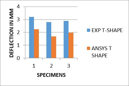
• Asthestressdecreasedtheloadcarryingcapacity and strength increases by using GFRP as comparedtonon Geopolymer specimen.
• Cracks are developed at the joint due to shear failure. It shows the cracking pattern in beam columnjoint.
1. Dineshkumar, K. L. G. (2021). Exterior RC Beam Column Joints Retrofitted with CFRP Sheets and theirSeismicBehavior 7(04),151 155.
2. June, M. (2017). Analytical Study Of T Beam ColumnJointUsingFEMSoftware 6(3).
3. Subramani,T.,&Piruntha,M.(2018). Behaviourof CRP Geopolymer Concrete Columns under Axial LoadingusingANSYS. 7,203 206.
load vs Deflection For T Shape with Geo polymer C3
Aswecanseein thegraph, deflection isincreasing asper loadsareincreasing.Alsostressandstrainandincreasing whenloadsareincreasing.
• The goal of the comparison of FE analysis results with the experimental test results is ensure that thepresentfinite element modelandanalysisare capable of predicting the response of the beam columnjoints.
• Comparison between the load Stress results obtained from finite element analysis for control andGeopolymerspecimensshowsthattheStress has significantly increased for the Geo polymer specimen. The Stress of GFRP specimens of T shape and L shape RG1, RG2 and RG3 are 63.15%, 17.04%, 13.04% Less than the Non retrofittedspecimen.
• The different configurations of GFRP considered or the specimens were by attaching to the top, bottom and lateral sides of beams. The results show that the stress, Strains are reduced as comparedtononGeopolymer specimen.
4. Rajan, C. S., Gopinath, G., Devaraju, A., & Anbarasan, B. (2020). Non linear analysis of double skinned composite hollow columns using geopolymer concrete. Materials Today: Proceedings, 39, 662 668. https://doi.org/10.1016/j.matpr.2020.09.186
5. Defalla, R., El, A., Rahman, A., Ahmad, M., & Khafaga, M. A. (2019). Analysis of Geopolymer Concrete Columns at Normal and High Strength. 11595 11604. https://doi.org/10.15680/IJIRSET.2019.0812019
6. Maranan, G. B. (2016). Structural Behaviour of Geopolymer Concrete Beams and Columns Reinforced with Glass Fibre Reinforced Polymer Bars. Ph.DDissertation, January,21 22.
7. Abdelwahed, B. (2020). Nonlinear numerical simulation for reinforced concrete elements with explicit time integration procedure. Case Studies in Construction Materials, 12, e00344. https://doi.org/10.1016/j.cscm.2020.e00344
8. Raj, S. D., Ganesan, N., Abraham, R., & Raju, A. (2016).Behaviorofgeopolymerandconventional concretebeamcolumnjointsunderreversecyclic loading. Advances in Concrete Construction, 4(3), 161 172.
https://doi.org/10.12989/acc.2016.4.3.161