International Research Journal of Engineering and Technology (IRJET) e ISSN: 2395 0056
Volume: 09 Issue: 06 | Jun 2022 www.irjet.net p ISSN: 2395 0072
International Research Journal of Engineering and Technology (IRJET) e ISSN: 2395 0056
Volume: 09 Issue: 06 | Jun 2022 www.irjet.net p ISSN: 2395 0072
1Ph.D Student, ED STII, Antananarivo University, Madagascar 2Professor, ED STII, Antananarivo University, Madagascar 3Professor, ED STII, Antananarivo University, Madagascar ***
Abstract - This paper presents the studies of localization system with a moving object in a delimited plane. The first work presents the trilateration system allowingthepositionof an object to be determined from known or more precisely measured distances. In this paper, the distance between the object and a sensor is evaluated using the measurement of the propagation time of a signal emitted by the object, here a sound waves. The definition of the departure time of the transmitted signal led to the study of two types distance measurement systems. The synchronous system of distance measurements, where the start time of the signal is known, and the asynchronous system where this time is unknown but an estimate is made to define it.
Key Words: Localization system, Plane, Trilateration, Distance, Sound wave, Synchronous system, Asynchronous system,
The use of robots, drones and ROVs are increasingly widespread in environments where humans do not have access. Robots, drones and ROVs are considered to be remotelypilotedunmannedvehicles.Therefore,knowingthe positionisveryusefulforbettercontrollingthemremotely, especiallywhentheyarenotwithinsight.
GPS is a location system in a fairly large reference frame, planetaryscale,whichdoesnothavemuchprecision,ofthe orderof5to15m.ThesignalsemittedbytheGPSsatellites donotarriveinthecoveredpremiseswhichcouldpossibly bepartoftheexplorationareasofunmannedvehicles.[1][2] [3]
Thus, could we use a positioning system for a delimited spacewithanacceptableprecision?Inordertoanswerthis problem,thisworkconsistsinstudyingalocalizationsystem usingtwocomplementarymethods.Thefirst,trilaterationto determinethepositionofanobjectfromthedistancesthat separateitfromfixedpoints.Thesecondisthemethodusing the propagation time of a signal to measure the distances betweentheobjectandthefixedpoints.
From this distance measurement system, we will see and comparetwodistancemeasurementmethodsdependingon theknowledgeofthestarttimeofthemeasurementsignal. Synchronous measurement consists of sending a signal to activate the measurement trigger of the sensors and the sendingofthesignalfromtheobject,whichallowsthemto besynchronizedsoastoobtainthestarttimeofthesignal. Theasynchronousmeasurementconsistsinestimatingthe departuretimeofthesignalusinganadditionalsensor.The deductionofthedistancesbetweensensorsandtheobject emittingthesignalisthusdonewithoutknowingtheexact momentofthesignaldeparture.
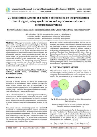
The trilateration method is a mathematical method for determiningtherelativepositionofapointP.Itconsistsof usingonlythedistancesbetweenfixedbasepointsandthe objects,andnottheanglesasbytriangulation.[4]
Fig 1 :IllustrationoftheobjectPpositiondetermination bytrilateration.
KnowingthepositionsofallbasesQandthedistances betweentheobjectPandallbases.[5]
AccordingtotheillustrationinFig 1,thedeterminationof thepointPisobtainedbytheintersectionofthe3spheresof respective radius r1, r2, r3 which are the distances of the objectcomparedtoallbasespoints.Thebasepointsdefined by the centers of the spheres (Q1, Q2, Q3) are fixed, and whosecoordinatesareknown,[1][2][5]
Q1: ,Q2: ,Q3: .
2022, IRJET | Impact Factor value: 7.529 | ISO 9001:2008 Certified

International Research Journal of Engineering and Technology (IRJET) e ISSN: 2395 0056
Volume: 09 Issue: 06 | Jun 2022 www.irjet.net p ISSN: 2395 0072
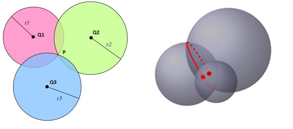
Equation1givestheresolutionbytrilaterationsameasthe intersectionofthreespheresin3D:
P1=( , )
and P2=( , ) (5)
(1)
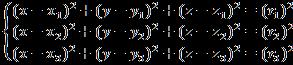
AsshowninFig 2,ina2Dcoordinatesystem(0xy),anobject canbelocatedusingtwoknownbasepoints.Thiswiththe knowledgeofthedistanceswhichseparatethesebasepoints to the object (r1 and r2), then by seeking the intersection pointofthetwocircles.
Thespaceofthis study beinga defined and limited space, andthattheorientationofthedevicescanalsobedefined, forequation5,onlyonevalueofPmustbechosen. Inthis work, the values of P1 that lie in the positive y axis were taken.
Positioning using the trilateration method requires measurementsofdistancesbetweentheobjectandthebase points.Thedistancemeasurementmethodusingthewave propagation time is studied for the measurement. This methodisbasedontheknowledgeofthewavepropagation speed, and as well as its departure time. The GPS system usesthismethod,aradiosignalorasoundsignalcanbeused asameasurementsignal.
Fig 2 : Graphicrepresentationof twocirclesintersection [6]
Equation 2isused todeterminetheintersectionpointsof thesetwocircles,dependingonthevalueof ρ
(2)
Threevaluesofρarepossible,andtheintersectionpointPof thetwocirclesdependonthesevalues.Theseintersection pointsaredefinedinequations3,4and5.
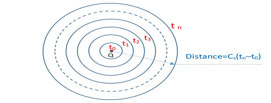
Fig 3 : Representationofthepositionofthesignalemitted frompointQateachinstanttandthedistancetraveled
By knowing the speed of the signal , the distance d traveled by the signal between two times and t can be deducedbytheformulaofequation6.
[4] (6)
if thentheequationhasnosolution.Thetwocircles donotintersect.[6] (3)
if The system admits a unique solution. The two circlesintersectatasinglepointP,[6]
With P=( ,0). (4)
if Thesystemadmitstwosolutions,Thetwocircles intersectintwopoints,P1andP2.[6]
The Fig 3 illustrates the radiation in the circles form described by the distances traveled at time tn , by a wave emittedfromapointQ.
For application of these two methods of positioning and distance measurement, the system studied in this paper consists of a device which emits the signal and by sensors whichmeasurethetimeofarrivalofthesignal.Thesesensors constitutethefixedbasepointsforthetrilaterationmethod.
2022, IRJET | Impact Factor value: 7.529 | ISO 9001:2008 Certified Journal
International Research Journal of Engineering and Technology (IRJET) e ISSN: 2395 0056
Volume: 09 Issue: 06 | Jun 2022 www.irjet.net p ISSN: 2395 0072
Knowingthestarttimeofthesignalaswellasthetimesofits arrival on the sensors, equation 6 can be directly applied. Here, the question thatarises is how to letthe positioning systemknowthestarttimeofasignalreceivedatatimeton oneofthesensors?
Twosynchronizationsystemshavebeenstudiedsothatthe systemcandeterminethisstartingtime.The synchronous system seen in paragraph 4 as well as the asynchronous system seeninparagraph5.
Thesystemiscomposedofanobjectthatemitsthesignalasa measurementbaseandtwosensorsthatdetectthearrivalof the signal. The calculation module, made up of a microcontroller,determinesthedifferencebetweenthestart time and the reception times of the signal emitted by the object to deduce the durations of the propagation of the signal. These times are used to determine the distances betweentheobjectandthesensors.
The system is defined as synchronous, because the object emitsacontrolsignalotherthanthepositioningsignalwhich allows the system to know the moment of emission of the positioningsignal.Thiscontrolsignalhasahigherspeedthan thatofthemeasurementsignal.
ForoursystemdescribedinFig 4,themeasurementsignalis a40kHzultrasoundsignalwithaspeedof0.34km/s,andthe control signal is an electromagnetic wave with a speed of 300,000km/s.Thereceiveddataistransferredtoacomputer throughamicrocontroller,tothenbeinterpreted.
t0isthedeparturetimeofthesignalwhichissynchronized with the measurement system of the arrival times of the measurementsignalonthesensors.t1andt2arerespectively thetimeswhenthesignalarrivesatsensors1andsensors2.
Thepositionsofthesensorsarefixedandimmobileandused asareferencebaseforpositioning.
Fig -4 :Blockdiagramofthelocalisationsystemandthe signalwithsynchronousmeasurement
4.1 System geometry, calculation and measurement
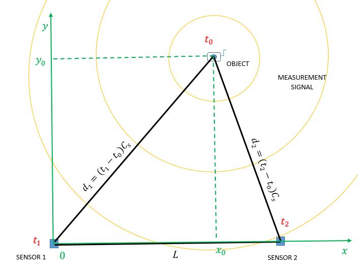
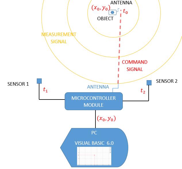
Figure5presentsthesystemgeometry.Madeupofthetwo sensors and the object, the whole forms a triangle. The determination of the coordinates x and y is obtained by intersectionofthetwocirclesofrespectiveradiusd1andd2 centeredonthepositionsofthesensors.
Fig 5 :Geometricrepresentationofthesynchronous systemwiththeknownsignalstarttime.
International Research Journal of Engineering and Technology (IRJET) e ISSN: 2395 0056
Volume: 09 Issue: 06 | Jun 2022 www.irjet.net p ISSN: 2395 0072
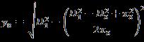
ThepositionPoftheobjectdefinedby ,is givenbytheequations7and8. (7) (8)
Fortheasynchronoussystemthecontrolsignalisremoved fromthetransmitterobject.Therefore,thestarttimeofthe signalisunknown.Inordertocompensatefortheignorance ofthisstartinginstant,athirdsensorisaddedtothesystem which gives another time t3 to solve the trilateration equationwhichisasystemofthree(3)equationswiththree (3)unknowns.
Thesystemisthereforecomposedofthetransmitterobject and also of a microcontroller module which calculates the differencebetweenthesignalreceptiontimesoneachofthe sensors(figure6).Thisgivesanestimateofthedurationsof thepropagationofthesignalfromtheobjecttothesensors. The time differences between the arrivals on the different sensorsareusedtodeducethepositionoftheobject.
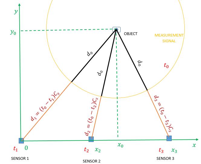
Figure7givesthesystemgeometrytodeducethenecessary equationstodeterminethepositionoftheobject.Thesystem equationfortrilaterationisgivenbyequation9.
Fig 6 :Blockdiagramofthelocalisationsystemandthe signalwithasynchronousmeasurement
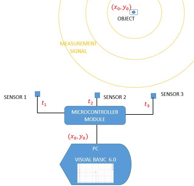
Fig 7 :Geometricrepresentationoftheasynchronous systemwith3sensors (9)
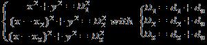
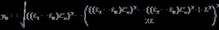
With equation 9, can be deduced and is given by the equation10. (10)
Hence, the object position, is given by the equation11. and (11)
The measurement time management is very important to haveagoodmeasurementresult,becauseitisnecessaryto
International Research Journal of Engineering and Technology (IRJET) e ISSN: 2395 0056
Volume: 09 Issue: 06 | Jun 2022 www.irjet.net p ISSN: 2395 0072
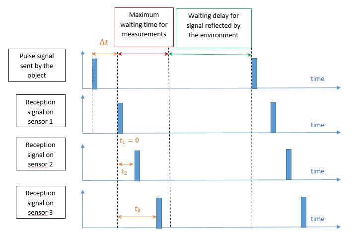
takeintoaccountthedelaystowaituntilallthedisturbing signalshavepassedbeforemakinganewmeasurement.Itis also necessary to take into account the maximum waiting timeforthemeasurements.Figure8givesthechronologyof eventswithintheasynchronoussystem.
Theinstant istakenasbeingtheinstantwhenthesignalis firstdetectedononeofthesensors.Themeasurementsofthe arrivaltimesofthesignalontheothersensorsaredefined from this moment. Also from this moment begins the countingofthemeasurementtimeinterval,whichisdefined asbeingshorterthanthetimebetweentheemissionoftwo (2)successivesignals.
Fig 8 :Chronologyofthesendingofthesignalbythe objectandreceptionofthesignalbythesensors, illustrationofanexamplewheresensor1receivesthe signalfirstandfromthismomenttheothertimesare measured.
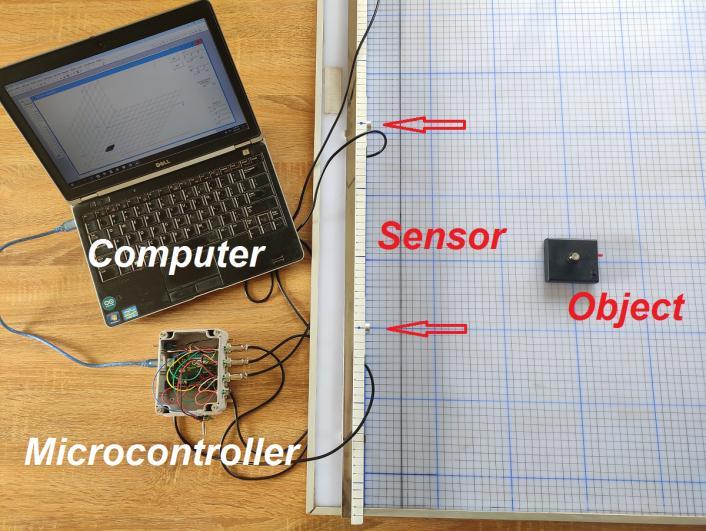
Figures9and10showthefieldandallthereferencepoints usedforthemeasurementsinthetests,andrespectivelygive thepositionsofthesensorsonthemeasurementbenchfor the synchronous and asynchronous systems. Figure 11 illustratesthemeasurementbench,thecalculationsystemas wellastheemittingobject(blackbox).
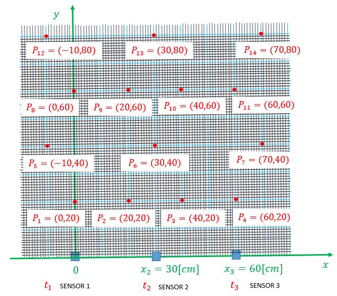
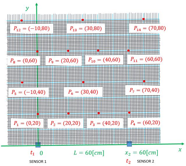
Fig 9 :Illustrationofthefieldandthepositionswherethe objectisplacedduringthemeasurementsona synchronoussystemwith2sensors
Fig 10 :Illustrationofthefieldandthepositionswhere theobjectsareplacedduringthemeasurementsonan asynchronoussystemwith3sensors.
International Research Journal of Engineering and Technology (IRJET) e ISSN: 2395 0056
Volume: 09 Issue: 06 | Jun 2022 www.irjet.net p ISSN: 2395 0072
Table1showthetimesofarrivalofthesignalsonthesensors for the synchronous and asynchronous systems from the object, and this for each position of the object. Table 2 represents the actual positions as well as the measured positionsoftheobjectforthetwomeasurementsystems.
Fig 11 :Themeasurementbenchsystem
Table 1:Timemeasurementonasynchronoustwo sensorsystemandonanasynchronousthree sensorsystemwith ultrasonicsignalasmeasuringsignal.
POINT MOBILEOBJECTPOSITION TIMESMEASURED SYNCHROUNOUSSYSTEM 2SENSORS
TIMESMEASURED ASYNCHROUNOUSSYSTEM 3SENSORS P X[cm] Y[cm] T1[µs] SENSOR1 T2[µs] SENSOR2 T1[µs] SENSOR1 T1[µs] SENSOR1 T1[µs] SENSOR1 1 0 20 589 1853 0 476 1271 2 20 20 824 1309 170 0 656 3 40 20 1311 827 655 0 171 4 60 20 1868 589 1270 476 0 5 10 40 1221 2368 0 461 1167 6 30 40 1465 1470 288 0 288 7 70 40 2370 1220 1152 447 0 8 0 60 1759 2485 0 211 735 9 20 60 1854 2118 65 0 338 10 40 60 2116 1854 338 0 64 11 60 60 2485 1764 735 209 0 12 10 80 2367 3132 0 268 767 13 30 80 2500 2506 153 0 152 14 70 80 3132 2369 765 269 0
International Research Journal of Engineering and Technology (IRJET) e ISSN: 2395 0056
Table 2:Positionscalculatedusingthetrilaterationmethodfromthetimesmeasuredonasynchronoussystemwithtwo sensorsandonanasynchronoussystemwith3sensorswithspeedofsound340[m/s]
POINT MOBILEOBJECTPOSITION[cm]
SYNCHRONOUSSYSTEM2SENSORS COORDINATESCALCULATEDBY TRILATERATION
ASYNCHRONOUSSYSTEM3SENSORS COORDINATESCALCULATEDBY TRILATERATION
P X[cm] Y[cm] X[cm] Y[cm] X[cm] Y[cm]
1 0 20 0.26 20.02 0.71 21.02
2 20 20 20.03 19.58 19.91 20.21
3 40 20 39.96 19.73 40.05 20.25
4 60 20 60.27 20.02 60.82 21.22
5 10 40 9.65 40.37 11.58 41.45 6 30 40 29.85 39.86 30.00 41.05
7 70 40 69.77 40.31 69.86 40.29
8 0 60 0.31 59.8 0.22 60.06 9 20 60 19.89 59.81 19.55 59.78 10 40 60 40.02 59.78 40.50 59.92 11 60 60 59.51 59.97 59.86 59.21 12 10 80 10.52 79.78 11.25 81.09 13 30 80 29.71 79.63 30.05 84.19 14 70 80 70.43 79.86 71.88 82.77
Chart 1 show the graph of absolute errors during measurements of the position of the object with the two measurementsystems.
Therefore,wecanseethesynchronoussystempresentsgood measurementresultswithanaverageerrorof0.37cm.The asynchronous system, on the other hand, presents a large variationinerrorswithanaverageof1.28cm.
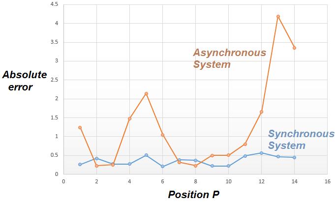
Chart 1:Graphoftheabsoluteerror,differencebetween themeasuredvalueandtherealposition,ofthe asynchronoussystemandsynchronoussystemdepending ontheposition.
Volume: 09 Issue: 06 | Jun 2022 www.irjet.net p ISSN: 2395 0072 © 2022, IRJET | Impact Factor value: 7.529 | ISO 9001:2008 Certified Journal | Page2060
International Research Journal of Engineering and Technology (IRJET) e ISSN: 2395 0056
Volume: 09 Issue: 06 | Jun 2022 www.irjet.net p ISSN: 2395 0072
This work has shown the adaptation of the trilateration methodfordeterminingthepositionofanobjectintheplane ofadelimitedspace.Forthesynchronoussystemofdistance measurements,theerrorsduetotheprocessingdelayofthe trigger signal are less important than those of the asynchronous system. The source of error of the asynchronoussystembeingtheestimationofthedeparture timeofthesignalfromthesource.
To further reduce errors on these systems, reviewing the Time to Digital Converter (TDC) system might help. A researchsubjecthasjustemergedfromthiswork,thesearch for the departure time of the signal for the asynchronous system. The asynchronous system is the most suitable for positioning an unmanned vehicle, because it makes it possible to reduce the payload of the vehicle and thus improveitsautonomy.
[1] F. Zafari, A. Gkelias, and K. Leung. “A survey of indoor localization systems and technologies.” https://arxiv.org/abs/1709.01015,2017.
[2]A.Mukhopadhyay;A.Mallisscry,“TELIL:ATrilateration andEdgeLearningbasedIndoorLocalizationTechniquefor EmergencyScenarios”,IEEE,2018.
[3]S.Sadowski;P.Spachos,“RSSI BasedIndoorLocalization WiththeInternetofThings”,IEEE,2018
[4] Geoffrey Blewitt, “Basics of the GPS Technique: ObservationEquations”,2000.
[5]X.Yan,Q.Luo,Y.Yang,S.Liu,H.Li,C.Hu,“ITL MEPOSA: Improved Trilateration Localization with Minimum UncertaintyPropagationandOptimizedSelectionofAnchor NodesforWirelessSensorNetworks”,IEEEAccess,2019.
[6]A.Bodin,L.Blanc Centi,N.Borne,B.Boutin,L.Desideri,P. Romon, “GEOMETRIE”, http://exo7.emath.fr/cours /livre geometrie.pdf,2016,
© 2022, IRJET | Impact Factor value: 7.529 | ISO 9001:2008 Certified Journal | Page2061