Comparison of Experimental and DELTA-EC Results on performance of Thermoacoustic Refrigerator
Ramesh Nayak B1 , Pundarika G21Department of Industrial Engineering and Management,B. M. S. Engineering College, Bengaluru 560019, India, 2Government Engineering College, Ramanagaram 562159, Karnataka, India ***

Abstract: The performances of thermoacoustic refrigerator under different operating conditions were studied experimentally and theoretically using DELTA EC model. The experiments were conducted for 0.12 mm thick parallel plate stack spaced at 0.36 mm of Mylar material and working fluid used was Helium. The resonator tube was made up of aluminium and inner portion coated with 2 mm thick of polyurethane to reduce the heat losses from conduction. The experiments were conducted with heating load (HL) ranging from 2 watts to 10 watts in steps of 2 watts with three drive ratios (DR) of 1.6 %, 1.8% and 2.0 %. Operating frequencies varies from 200 Hz to 600 Hz in steps of 100 Hz for a pressure of 10 bar. The temperatures were recorded using thermocouples at hot end heat exchanger and cold end heat exchanger for different operating conditions. The experimental results were compared with the theoretical results using DELTA EC model and performance of the thermoacoustic refrigerator was evaluated. It was observed that experimental and DELTA EC results were in correlation for all the parameters considered. However, deviation in the experimental results from the DELTA EC results at about 26% due to the viscous effects, discontinuities and turbulence present in the flow of the working gas and heat losses from the resonator tube.
Keywords: Resonatortube, Acousticdriver,Stack,Heat exchangers,Heliumgas
1. INTRODUCTION
Thermoacoustic refrigeration systems are used in various applications such as space cooling, commercial applications like beer cooler and cryocooler. The importance of thermoacoustic refrigeration is emerging technology because of its eco friendly operations. The various capacity of thermo acoustic refrigeration systems and prime movers designed and developed by Swift [1]. Rott [2] developed theoretical and mathematical based heat pumps and thermoacoustic refrigeration systems. Worlikar et al. [3 5] studied numerical simulation of the thermoacousti refrigerator for flow of the working substance and heat transfer in the stack. Tijani et al. [6 7] constructed a 4W cooling powerthermoacousticrefrigeratortostudytheinfluence ofspacingbetweenthestackplategeometryandPrandtl number of the working medium. They achieved 65oC minimum temperature. Qiu et al. [8] investigated
thermoacoustic refrigeration system under various parameters to characterize the thermoacoustic refrigeratorperformanceandvalidatedtheexperimental data. Electromechano acoustic network model was established to find the electro acoustic efficiency for various frequencies. Penelet et al. [9] studied the sound generation in thermoacoustic engines and experimental results were compared with the analytical results. The amplification of the sound causes the temperature difference in the thermoacoustic systems. Nsofor et al. [10]foundthetemperaturedifferenceof15oCacrossthe cold and hot ends of the heat exchangers for a parallel plate stack with the influence of critical parameters on theperformanceofthermoacousticrefrigerationsystem. Bheemsha et al. [11] developed 10 watts cooling load thermo acoustic refrigeration system using Helium gas astheworkingfluidandoptimizedthestackCOPas2.5. Tasnim et al. [12] evaluated the cooling power, the entropy generation and COP due to variation of process parameters in thermo acoustic refrigerator. Kamble et al. [13] studied the experimental and theoretical performance of thermoacoustic prime mover using different working substances and mixtures of the working substances. The performance of the thermoacoustic prime mover was found better at 60 % of Helium and 40% of Argon gases compared to other working gas mixtures. Dion and Bakhtier [14] evaluated numerically and experimentally the effect of the inertance diameter and various lengths of the tube. Performance of a pulse tube refrigerator was predicted using the computational fluid dynamic model. The computational model predicted the difference in phase angle between the velocity and pressure. The difference is least at the centre of the tube and the amplitude of pressure is more at the optimal inertance. Experimentally investigated to study the effect of inertance for various lengths and diameters of the tube. It was found that the experimental and numerical simulation results were similar trends for the all the parameters.
Nayak et al. [15 16] studied the performance of the thermoacoustic refrigerator for various operating parameters of heating load, frequency, drive ratios and pressures for different gases and stack geometries. The highest temperature difference is obtained for 2 watts heating load with operating frequency of 400Hz at 10 bar pressure across the cold and hot sides of the stack.
International Research Journal of Engineering and Technology (IRJET) e ISSN:2395 0056
Volume: 09 Issue: 06 | June 2022 www.irjet.net p ISSN:2395 0072
Nekrasova et al. [17] studied pulse tube micro cryocooler using linear thermoacoustic theory. The system was designed using numerical simulation and optimum parameters were obtained using this model. Relative Carnot efficiency of 21% was obtained by considering the operating parameters of 25 bar mean pressure,operatingfrequencyof70Hz,coolingpowerof 8 watts, and cold end temperature of 77 K using helium as a working gas. Saechan and Artur [18] was designed anddevelopedthestandingwavethermoacousticengine driven travelling wave thermoacoustic cooler. The thermoacoustic system was tested for different input power.−19.7°Ctemperaturewasachievedfromthecold side of the heat exchanger in the travelling wave thermoacoustic cooler for 2500 W heat supplied to the engine and relative coefficient of performance achieved was 5.94%. Fatimah et al. [19] demonstrated the vortex phenomenon across the two stack plates of 70 mm and 200 mm long and considered two operating frequencies of 13.1 Hz and 23.1 Hz. Reynolds number on the influenceofturbulenceonthevelocityprofilesinsidethe channelofthestackplateof70mmwas100andfor200 mmstackwas125.SaechanandIsares[20]designedthe travelling wave engine working at a frequency of 65 Hz usingairasworkingsubstanceatatmosphericpressure. They investigated the influence of various positions and lengths of the stub. The simulation and experimental result show the stub was used to maintain the acoustic wave propagated in the system. The maximum acoustic power was achieved at the optimal length and proper position of the stub. Chaiwongsa and Wongwises [21] studied the performance of an air based standing wave thermoacoustic refrigerator. They tested and compared the different blockage ratio of circular stack and spiral stack. Heat pipe having an input power of 30 W was mounted on the coldand hotheat exchangers.Heatwas transferred to the heat absorber by connecting the hot end of the thermoelectric module and heat was transferred to the cold heat exchanger through the heat pipes. Tests were conducted for an operating frequency rangesfrom120 Hzto 190 Hzwithanelectric powerof 20 W for both with and without cooling load. From the resultsitwasobservedthatCOPofthecircularstackhas morecomparedtotheCOPofthespiralstack.
2. EXPERIMENTAL PROCEDURE
Thermoacoustic refrigerator was designed and fabricatedfor10wattscoolingpower.Theimportant components of the thermoacoustic refrigerator are acoustic driver, resonator tube, stack, and heat exchangers. These components were designed based onthermoacousticequations[2].
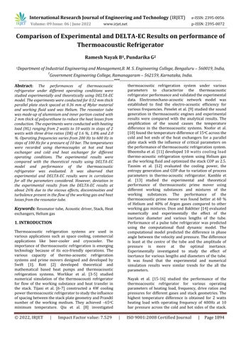
Figure 1 represents schematic diagram of the quarter wavelength thermo acoustic refrigerator consisting of a large and small resonator tubes, acoustic driver, stack and heat exchangers. The detailed specifications of the
thermoacoustic refrigerator is shown in Table 1 with parallelplatestackhaving69mmdiameterand40.5mm length made of Mylar sheets of thickness 0.12 mm at a distanceof0.36mmbetweentwoparallelplates.
Cold heat exchanger and hot heat exchanger were made up of copper tube and are fixed at both ends of the parallel plate stack. Heat is supplied to the cold heat exchanger and water is passed through the hot exchanger tube to maintain the atmospheric temperature. Resistance Temperature Detectors (RTD) were used to measure the temperature difference at hot end and cold end of the heat exchangers. Pressure transducers were used to measure the pressure in the resonator tube. Frequency of sound waves ranges from 100 Hz to 600 Hz with power supplied varies from 0 watts to120 watts to the acoustic driver. The frequency, pressure, and sound energy were measured using the BruelandKjearmeasuringdevices.
The tests were conducted to find the performance characteristics of the thermoacoustic refrigerator for different operating parameters. The working substance Helium was filled in the refrigerator with an operating pressure was maintained at 10 bar for varying drive ratios of 1.6%, 1.8% and 2% at different frequencies ranges from 200 Hz to 600 Hz. The properties of the Helium gas as shown in Table 2. The heating load which varies from 2 watts to 10 watts in steps of 2 watts was supplied to the cold heat exchanger. Once the system reaches the steady state, the tests were conducted for varying heating load and frequency. The data was recorded for each test and repeated the tests to set the required drive ratio for varying power supplied to the acoustic driver. Cooling arrangement was made to eliminate the heat from the hot heat exchanger and acousticdriver.
International Research Journal of Engineering and Technology (IRJET) e ISSN:2395 0056
Volume: 09 Issue: 06 | June 2022 www.irjet.net p ISSN:2395 0072
Table 1:SpecificationsoftheThermoacoustic
Refrigerator
Diameterofthelargeresonatortube D1 =70.07mm
Lengthofthelargeresonatortube L1 =85.5mm
Diameterofthesmallresonatortube D2 =30.92
Lengthofthesmallresonatortube L2 =238.91
Diameterofthestack D=69mm
Lengthofthestack L=40.55mm
Materialofthestack Mylarsheets
Diameterofthehotheatexchanger d1 =3.86mm
Lengthofthehotheatexchanger l1 =249.3mm
Diameterofthecoldheatexchanger d2 =1.93mm
Lengthofthecoldheatexchanger l2 =498.6mm
Materialoftheheatexchanger Copper
Table 2:PropertiesofHeliumgas
Soundvelocity a=1019.105m/sec.
Prandtlnumber σ=0.6835
Ratioofspecificheats γ=1.67
Driveratio D=2%=0.02
ViscousPenetrationdepth V =0.0987mm
ThermalPenetrationdepth K =0.1194mm
heating load and frequency. The electrical energy is converted to acoustic power in the acoustic driver. Coefficient of Performance and Relative Coefficient of Performance were used to measure the performance characteristicsofthermoacousticrefrigerator.
3.1 Validation
Experimental results obtained from the tests were compared with the DELTA EC results to find the performance characteristics of thermoacoustic refrigerator as depicted from Figure 2 to Figure 13. It was observed from the figures that both the experimental and DELTA EC results have the similar trend forall the conditions compared.The experimental resultsdeviatedfromtheDELTA ECresultsweredueto theviscouseffects,discontinuities,turbulencepresentin the refrigeration system and heat loss from the resonatortube.
3.2 Effect of Temperature difference (ΔT)
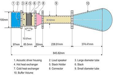
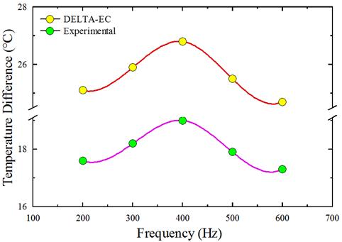
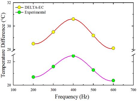
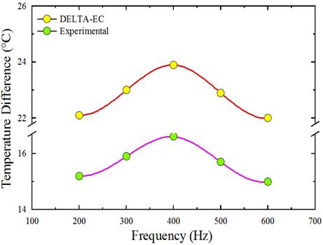
Figure2toFigure5showstheeffectoffrequencyonthe variationofthetemperaturedifference.Itwasfoundthat thedifferenceintemperatureincreaseswithanincrease infrequencyacrossthehot andcoldendsoftheparallel plate stack. The interrelation between the operating frequency and natural resonance frequency is the main reasontochangeintemperaturedifference betweenthe hotendandcoldendoftheparallelplatestack.
The performance of the thermoacoustic refrigerator depends on the thermoacoustic process inside the parallel plate stack. How the heat is transferred efficiently from cold end of the heat exchanger to the stack and from the stack to the hot end of the heat exchanger.
It was also found from both the experimental and DELTA EC results that the temperature difference increasesfrom200Hzto400Hzanddecreasesafter400 Hz due to the existence of sound energy which makes resonator to vibrate. The system will not be able to sustain because of higher input power of the loud speaker (acoustic driver). The viscous losses increase andthermoacousticeffectdecreasesduetotheexistence ofweakthermalpenetrationdepthinthestackathigher operatingfrequencies.
Figure1:Schematicdiagramofthermo acoustic refrigerator
3. RESULTS AND DISCUSSION
The performance characteristics of the thermoacoustic refrigerator was evaluated based on the input power to the acoustic driver, cooling power and temperature difference for different operating parameters like
The magnitude of the temperature difference between the hot end and cold end of the parallel plate stack was found 30.6oC for DELTA EC model compared to experimental results of 22.5oC at 2 watts heating load, 400 Hz frequency and 2% DR corresponding to a pressureof10bar.
Figure2:TemperaturedifferenceversusFrequencyfor 2Wheatingloadand1.6%DR
Figure5:TemperaturedifferenceversusFrequency for10Wheatingloadand2%DR
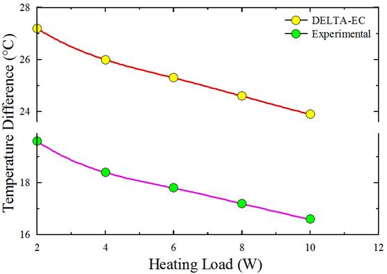
By considering Figure 6 and Figure 7, it represents the effect of heating load on the temperature difference for 10barpressureand400HzFrequency.Thetemperature difference depends on the dynamic pressure, heating load, frequency and drive ratio. Three drive ratios are used to measure the temperature difference across the stack using helium as the working substance. The temperature difference increases with an increase in drive ratio due to better viscous and thermal penetration depth as the spacing between the plates in the stack is very small. The drive ratio plays an important role in increasing the thermoacoustic effect leading to better heat transfer and temperature difference. The acoustic power supplied to the acoustic driverissufficienttoeliminatetheheatproducedatcold end of the parallel plate stack for lower heating loads andit is notsufficient to eliminatetheheat produced at higher heating loads due to low electroacoustic energy conversion efficiency of the acoustic driver. The temperature difference for DELTA EC model across the stack is more compared to experimental results at 2 wattsheatingloadand2%DRat400Hzfrequency.
Figure6:Temperaturedifferencewithheatingloadfor 400Hzfrequencyand1.6%DR
ISSN:2395 0056
Volume: 09 Issue: 06 | June 2022 www.irjet.net p ISSN:2395 0072
Figure7:Temperaturedifferencewithheatingloadfor 400Hzfrequencyand2%DR
3.3 Effect of Coefficient of Performance (COP)
From Figure 8 and Figure 9, it represents the effect of heating load on COP for different drive ratios. COP is proportionaltotheheatingloadandisincreaseswithan increaseinheatingload.Ithasbeenobservedfromboth theexperimentalandDELTA ECresultsthat the COP is morein lesser drive ratioandlessinhigherdrive ratio due to the effective thermal penetration depth in the stackandincreaseinacousticpowerinput.Thisleadsto efficientremoval ofheatatcoldendoftheparallel plate stack. It was found that the COP of DELTA EC is 2.598 andCOPoftheexperimentalresultsis2.205for10watts heating load at DR of 1.6%. COP of DELTA EC model is morecomparedtoCOPoftheexperimentalresults.
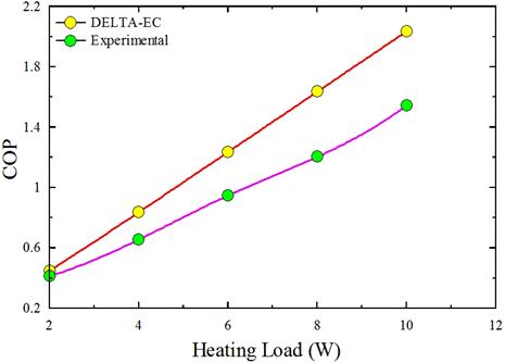
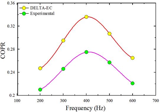
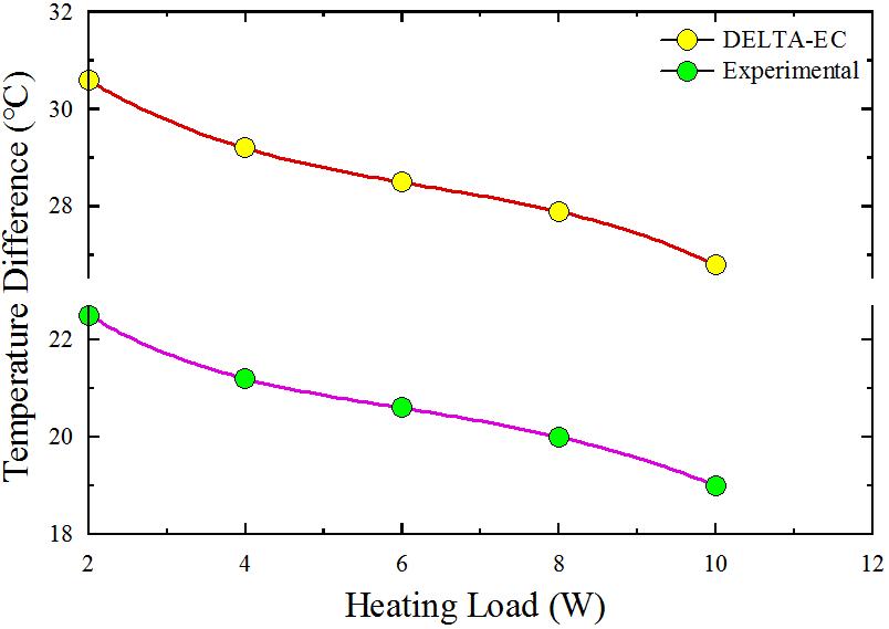
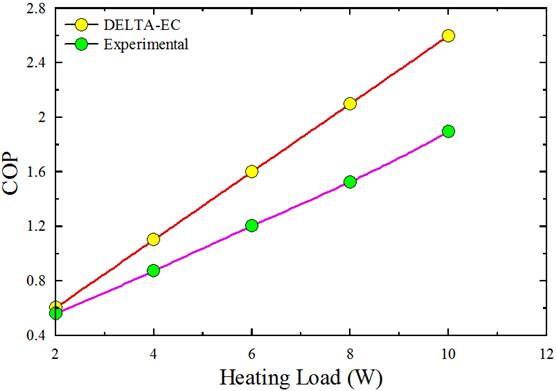
Figure9:VariationofCOPwithheatingloadfor400Hz frequencyand2%DR
3.4 Effect of Relative Coefficient of Performance (COPR)
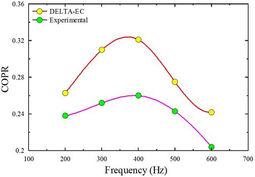
Figure 10 and Figure 11 represents the effect of frequency with COPR for parallel plate stack using helium as the working substance. COPR is proportional toCOP.ItwasobservedfromthefiguresthattheCOPRis maximum due tothespacingofthestack plates,viscous and thermal penetration depth on the performance of the thermoacoustic refrigerator. The COPR increases withanincreaseinCOPandthiswasobservedfromboth the experimental and DELTA EC results that COPR is maximum at 400 Hz frequency having a drive ratio of 1.6%with10wattsheatingloadforapressureof10bar. This was occurred due to the weak thermal penetration depth at high operating frequency in the stack by which there is decrease in thermoacoustic effect and increase in the viscous loss. COPR for DELTA EC is 0.336 and COPRforexperimentalresultsis0.275.
Figure8:VariationofCOPwithheatingloadfor400Hz frequencyand1.6%DR
Figure10:COPRversusFrequencyfor10Wheatingload and1.6%DR
Volume: 09 Issue: 06 | June 2022 www.irjet.net p ISSN:2395 0072
4. CONCLUSIONS
Tests were conducted to estimate the effect of thermoacoustic parameters on the performance characteristics of the thermoacoustic refrigerator for variousoperatingparameters.
Figure11:COPRversusFrequencyfor10Wheatingload and2%DR
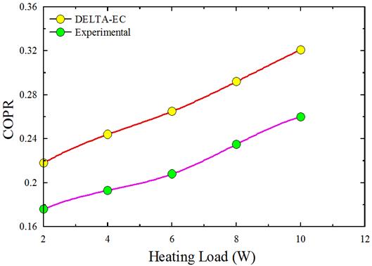
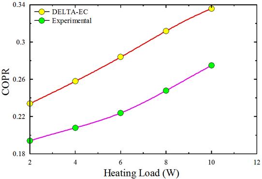
Figure 12 and Figure 13 indicates the effect of heating loadonCOPRfor400Hzfrequency.COPRincreaseswith an increase in heating load for a frequency of 400 Hz at 10barpressureforallthedriveratiosvariesfrom1.6% to2%.Lessamountofenergylosstookplaceduetoflow discontinuities and turbulence in the resonator at high velocities.
The maximum temperature difference achieved was 22.5oC and 30.6oC for experimental and DELTA EC model with parallel plate stack using heliumastheworkingsubstancecorrespondingto a 2W heating load at 400 Hz frequency for 2% DR of10barmeanpressure.
The COP obtained was 2.205 and 2.598 for experimental and DELTA EC model with parallel platestack using heliumas the working substance corresponding to a 10W heating load at 400 Hz frequencyfor1.6%DRof10barmeanpressure.
The COPR obtained was 0.275 and 0.336 for experimental and DELTA EC model with parallel platestack using heliumas the working substance corresponding to a 10W heating load at 400 Hz frequencyfor1.6%DRof10barmeanpressure.
The experimental results were compared with DELTA EC model. It was found that experimental and DELTA EC results have the similartrendforalltheparameters.
It was also noted that the experimental results deviate from that of the DELTA EC results at about 26% due to the flow discontinuities, turbulence and viscous effects present in the system in addition to conduction heat losses fromthesurfaceoftheresonatortube.
REFERENCES
Figure12:COPRwithheatingloadfor400Hzfrequency and1.6%DR
[1] Swift, Gregory W., Thermoacoustic engines and refrigerators,Physicstoday,1995,48,7.
[2] Rott, Nikolaus, Thermoacoustics inAdvances in appliedmechanics,1980,20,135 175.
[3] Worlikar, Aniruddha S., and Omar M. Knio, Numerical simulation of a thermoacoustic Refrigerator: I. Unsteady adiabatic flow around thestack,JournalofComputationalPhysics,1996, 127,424 451.
[4] Worlikar,AniruddhaS.,OmarM.Knio,andRupert Klein, Numerical simulation of a Thermoacoustic refrigerator: II. Stratified flow around the stack, JournalofComputationalPhysics,1998,144,299 324.
Figure13:COPRwithheatingloadfor400Hzfrequency and2%DR
International Research Journal of Engineering and Technology (IRJET) e ISSN:2395 0056
Volume: 09 Issue: 06 | June 2022 www.irjet.net p ISSN:2395 0072
[5] Worlikar, Aniruddha S., Numerical study of oscillatory flow and heat transfer in a loaded thermoacoustic stack, Numerical Heat Transfer: PartA:Applications,1999,35,49 65.
[6] Tijani, M. E. H., J. C. H. Zeegers, and A. T. A. M. De Waele, Design of thermoacoustic refrigerators,Cryogenics,2002,42,49 57.
[7] Tijani, M. E. H., J. C. H. Zeegers, and A. T. A. M. De Waele, Construction and Performance of a thermoacoustic refrigerator, Cryogenics,2002, 42,59 66.
[8] Tu, Qiu, V. Gusev, Michel Bruneau, Chunping Zhang, Ling Zhao, and Fangzhong Guo, Experimental and theoretical investigation on frequency characteristic of loudspeaker driven thermoacoustic refrigerator. Cryogenics, 2005, 45,739 746.
[9] Penelet, Guillaume, Vitalyi Gusev, Pierick Lotton, andMichelBruneau,Experimentalandtheoretical study of processes leading to steady state sound in annular thermoacoustic engines, Physical ReviewE,2005,72,016625.
[10] Nsofor,Emmanuel C.,and AzraiAli,Experimental study on the performance of the Thermoacoustic refrigerating system, Applied Thermal Engineering,2009,29,2672 2679.
[11] Bheemsha, Ramesh Nayak. B., Pundarika.G, Design and optimization of a Thermoacoustic refrigerator, International Journal of Emerging TrendsinEngineeringand Development, 2011,2, 47 65.
[12] Tasnim,S.H.,S.Mahmud,andR.A.Fraser,Effects of variation in working fluids and Operating conditions on the performance of a thermoacoustic refrigerator, International communications in heat and mass transfer,2012, 39,762 768.
[13] Kamble, Bharatbhushan V., Biju T. Kuzhiveli, S. Kasthurirengan, and Upendra Behera, Experimental and simulation studies on the performance of standing wave thermoacoustic prime mover for pulse tube refrigerator, International journal of Refrigeration,2013, 36, 2410 2419.
[14] Antao, Dion Savio, and Bakhtier Farouk, Numerical and experimental characterization of the inertance effect on pulse tube refrigerator performance, International Journal of Heat and MassTransfer,2014,76,33 44.
[15] Ramesh Nayak. B., Bheemsha, Pundarika.G, Performance evaluation of Thermoacoustic refrigerator using air as working medium, SSRG International Journal of Thermal Engineering, 2015,3,1 7.
[16] Nayak, B. Ramesh, G. Pundarika, and Bheemsha Arya, Influence of stack geometry on the performance of thermoacoustic refrigerator, Sadhana,2017,42,223 230.
[17] Nekrasova, S. O., E. A. Zinovyev, and A. I. Dovgyallo, Numerical investigation on a 70 Hz pulse tube micro cryocooler, Procedia Engineering,2016,152,314 320.
[18] Saechan, Patcharin, and Artur J. Jaworski, Thermoacoustic cooler to meet medical storage needs of rural communities in developing countries, Thermal Science and Engineering Progress,2018,8,164 175.
[19] Fatimah A. Z. Mohd Saath., Ernie Mattokt., Sitti H. A. Mustaffa., and Normah Mohd Ghazali, Numerical study of turbulence related to vortex shedding structure of an oscillatory flow in thermoacoustic energy system, Energy Procedia, 2019,156,239 243.
[20] Saechan, Patcharin, and Isares Dhuchakallaya, Design and experimental evaluation of a travelling wave thermoacoustic engine, Energy Reports,2020,6,1456 1461.
[21] Chaiwongsa Praitoon, and Somchai Wongwises, Effect of the blockage ratios of circular stack on the performance of the air based standing wave thermoacoustic refrigerator using heat pipe, Case Studies in Thermal Engineering,2021, 24, 100843.