International Research Journal of Engineering and Technology (IRJET) e ISSN:2395 0056

Volume: 09 Issue: 06 | June 2022 www.irjet.net p ISSN:2395 0072
International Research Journal of Engineering and Technology (IRJET) e ISSN:2395 0056
Volume: 09 Issue: 06 | June 2022 www.irjet.net p ISSN:2395 0072
Venkateshwaran Ramesh1 , Ezhilarasan A2
1,2UG students, Dept. of automobile Engineering, Sri Venkateswara college of Engineering, Chennai, India ***
Abstract Today's world is highly fast paced, and we all know how vital brakes are in this environment. The effectiveness of the braking system is critical in avoiding accidents and saving lives. In addition, the majority of car accidents are caused by brake failure. Here, I'm interested in learning about the reasons of hydraulic braking system failure. The brakes are a car's most significant active safety feature and one of its most critical components. Many drivers, on the other hand, do not appear to comprehend it. According to data, the brakes account for around 30% of the problems found by the ITV. When anything goes wrong with the automobile, bringing it to the shop isn't enough. Brake fluid leaks are a common occurrence. If brake fluid escapes in any situation, it may result in an accident. As a result, leakage and performance are critical. The pressure decrease in the brake fluid line suggests a problem with the braking system in this case. The front display shows that the pressure has dropped.
Keyword’s: Braking, Leakage, Failure, Safety, Pressure, Display
Intelligentsystemsthatremainwithinthecarandaidthedriverinanumberofwaysareknownasadvanceddriverinterface systems. This system displays virtual information on the state of an automobile component, as well as analyses the componentanddisplaystheresultsoftheanalysis(workingconditionandlifespanofthecomponent).Thebenefitofemployingthistechniqueisthatiteliminatesaccidentscausedbycomponentfailure.AccordingtotheNationalHighwayTraffic Safety Administration (NHTSA) National Motor Vehicle Crash Causation Survey, vehicle malfunctions such as braking failurecausearound 2%of all motorvehiclecrashes. Brakefailureis responsibleforaround22% of all automobile accidents.Byanalyzinganautomobilesubsystem(brake)anddisplayingvirtualdata.
MarcusBomer,HaraldStraky,ThomasWeispfenning,andRolfIsermanareamongthecastmembers.Aselectronicequipmentbecomemoreintegratedwithmechanicalcomponents,mechatronicsystems'problemdetectionanddiagnosticsbecomemorevital.Theworkofdefectdetectionmaybeseparatedintotwopartsingeneral.Thepresentprocessstatemust firstbederivedfromtheprocess'sobservableinputandoutputsignals inthefirst stage.Model basedfaultdetectionapproachessuchasparameterestimates,stateestimation,andparityequations,aswellassignal basedmethodssuchassignalspectrumestimation,canbeusedtodothis.Followingthat,thederivedcharacteristicsarecomparedtothefault free condition.Thiscausesavarietyofsymptomsthatindicatethepresenceofproblems.Thegoaloffaultdiagnosisinthesecondstageistodeterminethekind,magnitude,andlocationoftheproblem.
a) BrakeFaultDiagnosis:V.Indira,R.VasanthakumariMachinefaultdiagnosticsisabranchofmechanicalengineeringthat focuses on locating machine flaws. The most likely defects leading to failure were identified using a variety of approachessuchasvibrationanalysis,acousticemissions,thermalimaging,andsoon.Methodssuchasspectrumanalysis, waveletanalysis, and waveform analysis areusedtoanalysethevibration signals. Thistypeofstudy will provide youtheinformationyouneedtodecidewhenmaintenanceinterventionisnecessary.Thefindingsofthesestudiesare utilisedinfailureanalysistofigureout whatcaused thedefectinthefirstplace.A machinelearning techniquecanbe usedtodothisfailureanalysis.
b) FaultDiagnosisofHydraulicBrake:R.Jegadeeshwaran,R.JegadeeshVibrationsignalsfromacarwillbenon stationary duetowearandtear.Toovercomesuchissues,datamodelling employinga machinelearning techniquemight beapplied. Feature extraction, feature selection, and feature categorisation are the three fundamental phases in machine learning.Statisticalfeatures,autoregressivemovingaverage(ARMA)features,histogramfeatures,andwaveletfeatures areallexamplesoffeatures.Statisticalcharacteristicswereemployedinthisinvestigation.
Thehydraulicbrakingsystemisdesignedtooperateinaclosedenvironment.Abrakepedal,numerousswitches,areservoir, brake lines, various cylinders, linkages, pistons, and braking fluid make up the brake system. The reservoir, master
International Research Journal of Engineering and Technology (IRJET) e ISSN:2395 0056
Volume: 09 Issue: 06 | June 2022 www.irjet.net p ISSN:2395 0072
cylinder, and brake lines are all immobile, whereas switches and pistons are constantly moving. Damage to any of these componentscanleadtobrakefluidleaks,whichcandamagethevehicle'sbrakingperformanceandreaction.
There are various scenarios in which a vehicle's brakefluid leaks. A leak might becoming from one of the rubber hoses, brakingcalipers,wheelcylinders,ormastercylinders.
Whetherthelineshaveahole,asplit,oradamagedportion,brakingfluidwillbegintoleak.Whenbraking,thelines that transport the liquid back and forth through the brake system will cause a quick shift in sensation. The brake pressure will not be present due to the hole or breaking in the line, therefore it will feel and maybe not deliver enoughstoppingforce.
The fluidfrom the brakeis sometimes removed by the bleedervalve's bolts or valves andsentto othersections of thebraking system.Itistypicaltohavebraking issues whenitfails.Thisusuallyoccursafterthe brakes have been replacedorthefluidhasbeencleaned,andtheboltshavebeentightened
Themastercylinderisthecomponentofthebrakingsystemthroughwhichthemajorityofthebrakefluidgoes.Itis oneofthemostprevalentcausesofbrakefluidleakssinceittendstoweardownwithtimeandmileage.
Whena wheel cylinder or caliper is damaged, it begins toleak fluid. Whenthis happens, the most revealing signis brakingfluidonthewheel'sedges,astheliquidtendstoseeptowardsthewheelwhenitleaks.
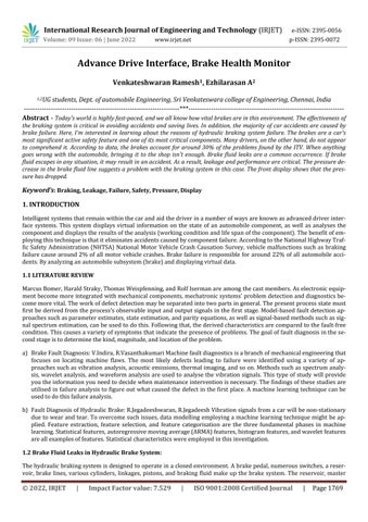
AdriverInterfacesystemwillbecreatedusinganArduinomicrocontroller. TheArduinomicrocontrollercontrolstheinterfacescreen.Theinterfacescreenreceivestouchinputfromtheend user.Thentheinterfacescreensprovideengineering vehicle information to the end user. Provide technical feedback for drivers who are interested in gaining knowledge abouttheirvehicleinformation.TheBrakeHealthMonitortomodifydrivingcycle.Thelocationoftheinterfacescreenisin the
International Research Journal of Engineering and Technology (IRJET) e ISSN:2395 0056
Volume: 09 Issue: 06 | June 2022 www.irjet.net p ISSN:2395 0072
vehicledashboard.Andthemountingplaceshouldnotbeinablindspot.Andtheend usercanaccesstheinterfacescreen withoutanydisturbanceandtheinterfacescreenalsoshouldnotdisturbanyotherpartsofthedashboard.Thebrightness ofthescreenshouldbeinlowormedium.Becausethebrightnesswilldistractthedriver.Thecordlesstransceivermodule is a compact design and circuit. The Auto Cad 3D modeling (fig. 2) shows the mounting tabs in a model car dashboard. Thosereddotsaresuitableplacesfortheinterfacescreenmount.
Displaythefollowingfeaturesinthedriverinterfacescreen.
Thepressureofbrakefluid
Pressureleakinthehydraulicbrakesystem
Conditionofthehydraulicbrakesystem
Thetemperatureofabrakedisc(Rotor)
Inadditiontotheadvancementofnewtechnologies,thedesignprocessintheindustryhaschangeddramaticallyinrecent years. For sophisticated embedded systems, Model Based Design is now widely employed in the automobile, aerospace, andothersectors.Atraditionaldesignworkflowcontainsthefollowingsteps:
Requirement
Implementation
TestandValidation
Simulink is a graphical programming environment that uses MATLAB to model, simulate, and analyze multi domain dynamicalsystems.Ithasagraphicalblockdiagramtoolandaconfigurablecollectionofblocklibrariesasitsprimaryinterface.
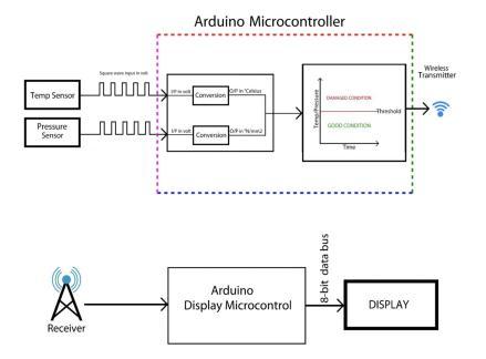
Thebrakepressureleaksimulationmodalhasaphysicalvehiclebrakesystemmodelandsimulationvehiclebrakesystem model. The pressure leak only occurs in the physical vehicle model. Brake input block and pedal displacement to pedal forceblockaregivingbrakepedalforce(inkg)tothephysicalandsimulationsystemmodel.Theblocksareshownbelow in(Figure.3)Hydraulicbrakesystemmodelblock
Fig 3:Hydraulicbrakesystemmodelblock.
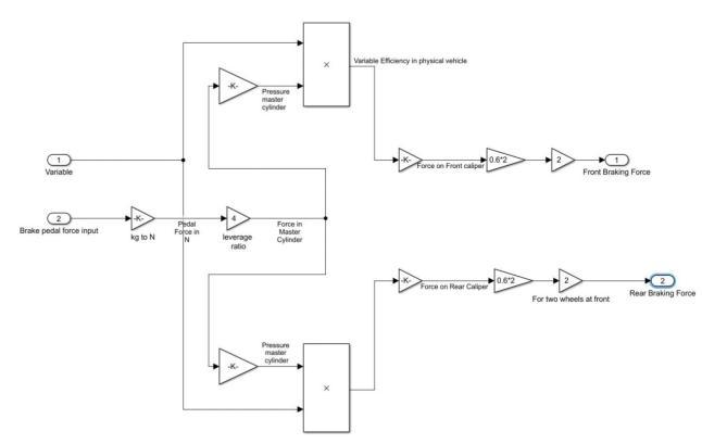
Thephysicalvehiclebrakesystem is gettingthebrakepedalforceandleak manipulationvariablefromleak manipulator sub blocks.Thebrakepedalinput forceisdriverappliedforce.Andusedgainblockstocalculatetheforceonthemaster cylinder. Thenusingproductblocktocalculatevariableefficiencyinthephysicalvehicle.Finally,thefrontwheelbraking forceandrearwheelbrakingforcearecalculated.Theblockisshownbelow(Figure.4)Physical
2022, IRJET | Impact Factor value: 7.529 | ISO 9001:2008 Certified Journal |
International Research Journal of Engineering and Technology (IRJET) e ISSN:2395 0056
Volume: 09 Issue: 06 | June 2022 www.irjet.net p ISSN:2395 0072
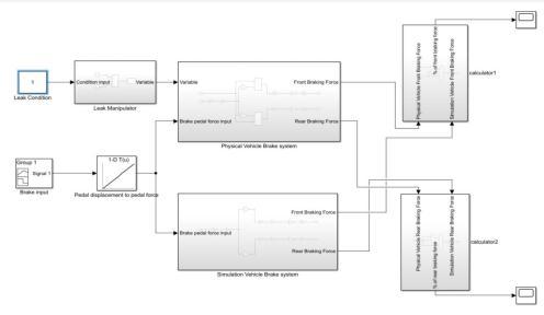
Fig 4:Physicalbrakesystemmodelblock.
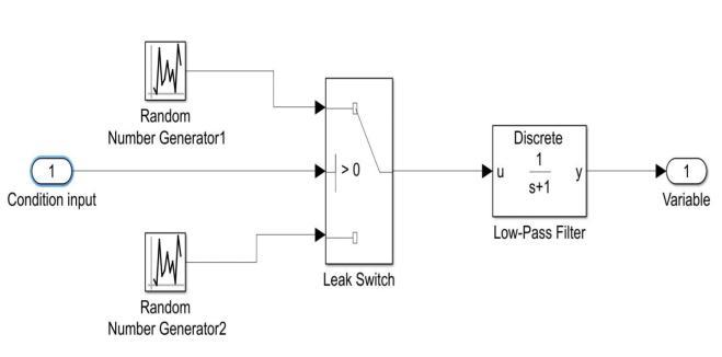
Leak manipulator is creating a pressure leak in the physical vehicle brakesystem. Thisleak manipulator is getting input from a constant block. There is a pressure leak if the value of the constant block is one, otherwise, there is no pressure leak.Andtherandomnumbergeneratorisusedinthis model.Here,thelowpassfilterisusedtoreducethenoiseinthe signal.Theblockisshownbelowin(Figure.5)Leakmanipulatormodelblock.
Fig 5:Leakmanipulatormodelblock
The simulation vehicle brake system is getting the brake pedal force from the bake input block and pedal displacement. The brake pedal input force is driver applied force. And used gain blocks to calculate the force on the master cylinder. Thenthefrontwheelbrakingforceandrearwheelbrakingforcearecalculated.Thereisnopressureleakinthesimulation vehiclebrakesystem.Theblockisshownbelowin(Figure.6)Simulationvehiclebrakesystemmodelblock.
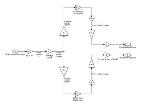
Fig 6:SimulationVehiclebrakesystemmodelblock.
2022, IRJET | Impact Factor value: 7.529 | ISO 9001:2008 Certified
International Research Journal of Engineering and Technology (IRJET) e ISSN:2395 0056
Volume: 09 Issue: 06 | June 2022 www.irjet.net p ISSN:2395 0072
Therearbrakingforcesofthephysicalvehicleandsimulationvehiclebrakesystemarecompared.Finally,thepercentage ofrearwheelbrakingforceiscalculated.ThePercentageofRearWheelBrakingForceModel.
Eventually,thissimulationmodelwillbecreatedfourgraphs.Thegraphsshowthechangeinbrakeforcecomparingwith theidealmodel.Withoutpressureleak,theactualmodelhasasmallchangeinforce20percentageofbrakingforce.Andit isreducedfromtheidealmodel.Butinwithleakmodel,thebrakingforcechanges58percentagewithrespecttotheideal model. By analyzing the graphs, set 53 to 59 percent braking force as a threshold point. When the braking force goes around53to59percent,thereisapressureleak.
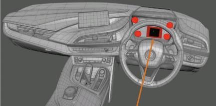
Thebrakehealthmonitoris dividedintotwounits whicharebrakeunitanddashboardunit.Theseunitsarefixedindifferent places ofthe vehicle. So,theNRF23L01 transceiver modulehelps to communicatewith each other. Both units can transmitthedataaswellasreceivethedata.Whenthebrakeunitistransmittingthedata,thedashboardunitisreceiving thedatafromthebrakeunit.Therearenodatalossesbecauseitiscordless.AndthisNRF23L01transceivermodule'sfrequencyrangeis2.3GhzISMband.
The pressure transducer is mounted on the brake line by T joint. The brake pedal has a stopper at some constant point. Thisstopperwillnotallowthebrakepedaltogofurther.Nowconductthetestonthegoodconditionofthebrakeline,the transducerwillsendavoltagesignaltotheArduinoUnomicrocontroller.Thevoltagesignalsarealreadycalibratedtothe appropriatepressureunits(N/mm2).Themicrocontrolleriscontinuouslymonitoringbrakepressureattheconstantbrake force. Andthetests willconductinthedifferentbrakeforces.Setthisconstant brakepressureasa threshold atconstant brake pressure and when the pressure goes below the threshold at the constant condition, there is brake fluid pressure leak.ThesedataarestoredinthelocalArduinoUnomicrocontroller.
Theinfraredtemperaturesensorismountednearthediscbrakerotor.Thisbrakerotorisadynamicobjectwhichmeansit is spinning. So, the sensor takes 120 milliseconds to measure the temperature of the rotor. And this sensor sends direct temperatureoutputArduinoUno(Thissensorhasabuilt inlibrarysononeedtocalibrateit).Thesedataarealsostored inthelocalArduinoUnomicrocontroller.
ThebrakeunitArduinoUnomicrocontrollerstoresdatafromthepressuretransducerandtheinfraredtemperaturesensor. And the stored data are compared to the reference data (it is an open loop system) and processed by Arduino Uno microcontroller.ThoseprocesseddataaretransmittingviaradiosignalsbyusingtheNRF23L01transceivermodule.
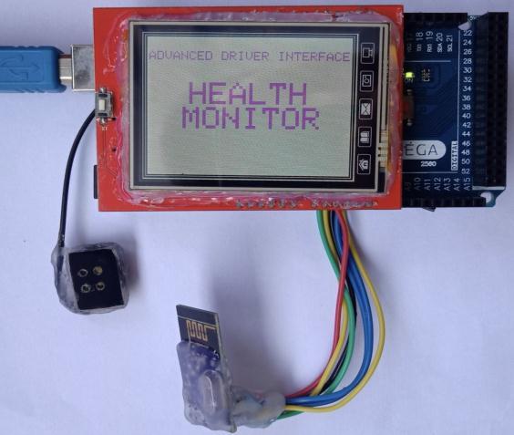
The dashboard unit's NRF23L01 transceiver module receives those signals from the brake unit's transceiver module. Dashboard Arduino Mega 2560 microcontroller receives data from this transceiver module. And the microcontroller is storedthisdatainitsflashmemory.
The 2.3" TFT touch shield is controlled by Arduino Mega 2560 and it programmed in Arduino IDE (Arduino Integrated developmentenvironmentARM63bits)software.Thesensorsaretransmittingreal timedatatoArduinoMegamicrocontroller and this microcontroller is processing the data and displays it in the interface screen. The driver interface screen receives input from the end user by touch the screen (Figure.7) shows how the brake health monitor Internal interface lookslike.
International Research Journal of Engineering and Technology (IRJET) e ISSN:2395 0056
Volume: 09 Issue: 06 | June 2022 www.irjet.net p ISSN:2395 0072
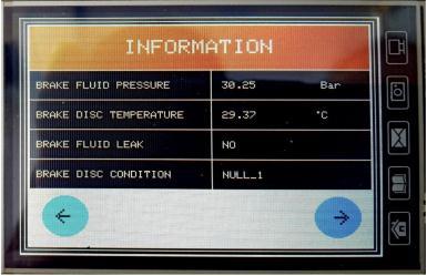
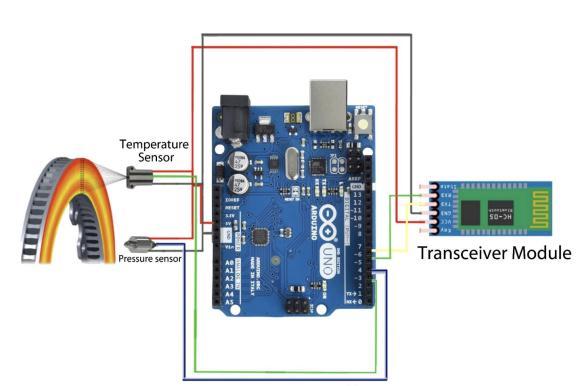
Fig 7:BrakehealthmonitorInternalinterface
The interface screen displays real time data.And the dashboard unithas a buzzer. The buzzer will alert the driver if the brakesystemhasafailure.(Figure.8)showsvirtualinformationtotheend user.
Fig 8:virtualinformationtotheend user.
DisplayedVirtualInformation(Figure.9):
Brakefluidpressure
Brakedisctemperature
Brakefluidleak
Conditionofbrakesystem
Fig 9:Brakehealthmonitoruserinterface
International Research Journal of Engineering and Technology (IRJET) e ISSN:2395 0056
Volume: 09 Issue: 06 | June 2022 www.irjet.net p ISSN:2395 0072
Throughthecourseofthisreport,adetailedsimulationofamodelforavehiclebrakingsystemhasbeendescribed.DevelopedthedriverinterfacetoolbyusingtheArduinomicrocontrollersandTFTtouch screenshield,which providesvirtual informationandprecautionaryalertaboutthebrakesystemofthevehicle. Wirelesscommunicationofdatafromsensors to the interface is incorporated through Telemetry. Modelling of the advance driver interface to simulate the working principleofahydraulicbrakesystemhasbeenpresentedindetail,satisfyingallitsparameters.
1) MarcusBomer,HaraldStraky,ThomasWeispfenning,andRolfIsermanareamongthecastmembers.Vehiclesuspensionandhydraulic braking systemissue detectionusing models.Volume 12, Issue 8,October2002, Pages 999 1010, DarmstadtUniversityofTechnologyLandgraf Georg Str.3,D 63283Darmstadt,Germany,InstituteofAutomaticControl,LaboratoryofControlEngineeringandProcessAutomation,DarmstadtUniversityofTechnologyLandgraf Georg Str.3,D 63283Darmstadt,Germany
2) R.Vasanthakumari,V.IndiraClonalSelectionClassificationAlgorithm(CSCA) astatisticallearningmethod isusedto diagnosebrakefaults.Volume18,Issue1,March2015,Pages59 69inEngineeringScience&Technology,anInternationalJournal.
3) R.Jegadeeshwaran, V.Sugumaran. Fault diagnosis of automobile hydraulic brake system using statistical features and supportvectormachines.MechanicalSystemsandSignalProcessing.Volumes52 53,February2015,Pages336 336.
2022, IRJET | Impact Factor value: 7.529 | ISO 9001:2008 Certified