1
International Research Journal of Engineering and Technology (IRJET) e ISSN: 2395 0056

Volume: 09 Issue: 06| June 2022 www.irjet.net p ISSN: 2395 0072
1
International Research Journal of Engineering and Technology (IRJET) e ISSN: 2395 0056
Volume: 09 Issue: 06| June 2022 www.irjet.net p ISSN: 2395 0072
2,3,4,5 B.E., Dept. of Mechanical Engineering, Thakur College of Engineering and Technology, Mumbai, India ***
Abstract Additive Manufacturing (AM) is a discipline in manufacturing technique by which the product or the prototype is developed layer by layer. AM uses 3D printing approach majorly, out of other forming methods. It is capable of handling CAD model with varying complexity in terms of designing and incorporates manufacturing. When compared to traditional manufacturing, AM requires fewer tools in regards to the space and physical inventory, it saves a lot of resources financially. It also consists ofadigitalinventory.The unlimited adaptability of component production is the primary benefit. Now, Layer Thickness is an important aspect in 3D printing. Layer Thickness is a measure of height of each successive layer of material addition in additive manufacturing process. Layer thickness governs the overall surface, and product quality of the component under process. Effect of layer thickness can be seen majorly in terms of surface finish and print time. Increasing layer thickness decreases print time is a known fact. Thus, this paper intends to experimentally establish a logical relation between the surface roughness andlayer thickness.Thiscanbeachievedby 3D printing components each with different layer thickness, calculating surface roughness of each component and then finding out governing relation between the two. This logical relation can be helpful while trading off between print time and surface finish.
Key Words: Additive Manufacturing, Layer Thickness, FDM, Surface Roughness, 3D Printing
Additive Manufacturing (AM) is a modern name for 3D printing. AM is a layer by layer creation procedure that changestheCADmodel straightforwardlyintocompletely complex designs. AM requires less tools with regards to space and physical inventory savings. It has a digital inventory.TheprimarybenefitofAdditiveManufacturingis that it has an unlimited adaptability to produce a complicated part. The term '3D printing' can allude to an assortment of cycles wherein material is saved, joined or fusedunderPCcontroltomakethreelayeredobjects,with material being added together. [1] Around the 1980s, 3D printing methods were viewed as reasonable just for the developmentofusefuloraestheticmodels,andamorefitting term for it at the time was rapid prototyping. Starting in
2019,theaccuracy,repeatability,andmaterialscopeof3D printinghaveexpandedtothepointthatsome3Dprinting processes are viewed as suitable as a modern creation innovationbywhichthetermAdditiveManufacturingcanbe utilizedequivalentlywith3Dprinting.[2]
Additive Manufacturing is basically utilized by specialists, designers, and development administrators, and has supplantedmanualdrafting.[3]Itassistsclientswithmaking plans in three aspects to envision development, and empowerstheturnofevents,change,andstreamliningofthe plan interaction. This interaction assists engineers with making more exact portrayals and adjusting them all the more effectively to further develop plan quality. Additive designing is advancing at a quick speed. 3D printing presently includes metal laser sintering, powder bed combination, and, surprisingly, crossover strategies includinganalyticalandrobotics.Ithasbeenembracedby majormodernorganizationssearchingforwaysofworking ontheiritems.Thecapacitytoconveyclosemomentparts creation and completely specially crafts that cannot be recreated with other assembling procedures has sped up ventureandexaminationinaddedsubstancedesigning.[4]
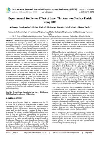
Prior to slicing/cutting, the CAD model is tessellated, for example changed over into across section of triangles to shapetheexternalshellofthearticleandisputawayinthe STLfileformat,whichisupheldbytheRPmachines.[5]The waytowardchanging over theCAD intoacross section of trianglestoframetheexternalsurfaceoftheitemiscalled tessellation. This is asignificant advance as the process parameter,forexample,build time,partqualityandsurface roughnessrelyuponthedegreetowhichthemodelhasbeen tessellated.Themoretessellatedamodelis,themoreisthe structuretime,andmoreisthedimensionalprecisionofthe actualmodelincontrastwiththeCADmodel.[6]
Priorto beingsliced,theslicingprogrammingpermitsthe end user to settle on a decision of the direction and cut thickness (layer thickness) which enormously sway item fabricatingtime,materialtobeutilizedandrelatedexpense, surface quality and the quantity of extra constructions knownashelpstructures.[11][7]
International Research Journal of Engineering and Technology (IRJET)
e ISSN: 2395 0056
Volume: 09 Issue: 06| June 2022 www.irjet.net p ISSN: 2395 0072
FollowingaretherequirementsthatanSTLfileformatmust satisfy:
1.Eachfaceofthetrianglemustshareonlyoneedge withtheadjacenttriangle.[8][9]
2.Thevertexofanyonetrianglecannotlieontheedge ofanyothertriangle[8].Whenthepartisviewedfrom external end, the vertices of the triangle should be placedinanti clockwisedirection.Thenormalvector ofeachtrianglemustbepointingoutside.[9]
MostoftheCADsystemsfailtosatisfythesenecessitiesand effectindefectssuchasmissingfacets,overlappingfacets, holes,cracksandinaccuratenormal.[8][10]
component.Theslicingsoftwareconvertsthe3Dmodelinto acodethatinstructstheprintertoprintit.Manyadditional featuresneedtobedeterminedduringtheslicingprocess. Userneedstogiveparametersasaninputduringtheslicing, for example infill density, layer thickness, printing orientationetc.Someparametersarefixedandneednotto bechanged,likeprintingspeed,controllingprintingspeed mayleadtobadqualityofproduct.[12]
Fig 1:StandardTessellationLanguageFormat ComponentinSolidWorks
ExaminethebehaviorofthequalityofPLAmaterial forFDMprocessparameters.
Flashforge Guider IIs is proved as a good choice for small productionwithitsbigbuildvolumeaswellasfeaturessuch as great compatibility of materials and extruder system, Guider IIs delivers strong functions with industrial grade accurate parts and quality.With the strong functional features,itallowsmuchfreedomtoproduceaccuratework andenhanceproductivity.
FindingtheoptimumcombinationofFDMprocess parameters like layer thickness for better part quality.
● Video Monitoring printing process with a built in HDcamera
Analyzing the relationship between the FDM process parameters and comparing it with the mechanical properties. Thereby, examining the resultsusinggraphicalinterpretation.
● Durable and industrial grade extruder for maximumprinttemperatureupto300℃
● Massivebuildvolume:280*250*300mm
● Open1.75mmfilamentsystem
FDM Process Parameters: Layer thickness with constantOrientationandInfilldensity
Mechanicalproperties:SurfaceRoughness
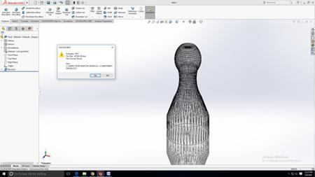
As we are printing the model using the FDM process, the printerwehavechoseninFlashforgeGuideIIsasshownin Figure3.1.Itsuniquefeatureisthatithasaclosedboxwhich allowstheefficientcontroloftemperature.Flashforgeguider IIs uses software named FlashPrint for slicing the
● 5 inchtouchscreeninterface
● Auto bed level system ensures the platform is leveledbeforeprinting.
The Flashforge Guider IIs is equipped with HEPA filter, which protects your working environment from potential dustproducedintheprocessofprintingindustrialfilament.
2022, IRJET | Impact Factor value: 7.529 | ISO 9001:2008 Certified
International Research Journal of Engineering and Technology (IRJET) e ISSN: 2395 0056
Nozzlediameter 0.3to0.8mm
Maximumextruder temperature 300:C
Printspeed 30 100mm/s
Maximumplatform temperature 120:C
LayerThickness 0.1 0.4mm
Filamentcompatibility PLA,HPS,ABS,PETG,PC, ASA
Screendimension 5 inchTouchscreen
InternalStorage 8GB RunningNoise 55dB Power 500W
Connectivity USB,Wi Fi,Ethernetetc. Softwareandfileformat FlashPrint(STL,OBJ,BMP, PNG)
Fuseddepositionmodelling (FDM)isa fast growingrapid prototyping (RP) technology due to its ability to build functional parts having a complex geometrical shape in a reasonabletimeperiod.Customisationofmaterialproperties byrouteofcontrollingtheprocessparametersisalandmark ability of the additive manufacturing (AM) processes.[13] FDM is a complex process that exhibits much difficulty in determining optimal parameters due to the presence of a largenumber ofconflicting parametersthatwill influence thepartqualityandmaterialproperties.[14].Thequalityof builtpartsdependsonmanyprocessvariables.[13]
Hence,itisabsolutelynecessarytounderstandtheprocess parameter such as materials used, printing delay, build orientation, print head resolution, geometric features and their topology, post treatment procedures, binder drop volume,binderpowderinteraction,particlesizeandlayer thickness that will influence the surface quality, part strength,buildtime,accuracyandrepeatability[15].
Build parameters that have an effect on the physical propertiesof3Dprintedsamplesconsideredforthepresent studyisgivenbelow:
Also known as layer height or vertical resolution is the thicknesswithwhichtheprinterheadprintsasinglesliced layer.Layerheightisanimportantparameterasitgoverns thesurfacefinishofthefinalmodel.Lowerthelayerheight, higherthesurfacefinish.However,buildtimeincreasesifwe reducethelayerheightandlayerheightcannotbereduced belowacertainlimit.[16]
This parameter describes the direction in which the 3D model is to be printed. Once the model is loaded onto the slicing software, the orientation of the model can be changed.Theprinterthenprintsthemodelintheselected orientation.Thisparameterhasasignificantimpactonthe strengthofthematerialandtheprintingtime.Bychanging printorientation,supportrequirementscanbereducedor sometimeseliminated.
3.2.3
Fill density/ Infill describe the density with which the materialisfilledwithintheoutershellofthemodel.Thefill density may vary from a 0% to a 100%. The 100% fill density represents a solid block whereas the 0% of it represents an object with only an outer shell. Mechanical strength increases with increase in fill density, but has longer build times. With increase in fill density, Material requirement and weight of the component also increases. Therearevariousinfillpatternsavailable.
3.3
Additivemanufacturingisbasically3Dprinting.Ratherthan simply using conventional machining techniques which include wastage of materials by removing unwanted fragments,additivemanufacturingdepositslayerafterlayer creating objects. It is comparatively a more flexible technologythansubtractivemanufacturing.Sincetechnology isadvancingdaybyday,newmaterialsarebeingcreatedto get desired properties that can be applied to the required functions. This literature review mainly focuses on the propertiesofpolymericmaterialsthatareavailableandused for3DprintingandtheirimpactinthemarketofAM.Since various kinds of polymeric materials are available, the manufactureroftheproductwouldpreferthepolymerwith the optimum conditions for the required objective. For example,optimumstrength isrequiredfor manufacturing andprototyping.Garmentindustryrequireshighelasticity. For a function of insulation high thermal resistivity is desired.Highductilityisrequiredforwiringandcircuitries. Aerospace industry calls light weight polymers. Higher toughnessisrequiredforsupportingmaterials.Anoptimum melting point is essential for temperature dependent environmentalfactorsthatareexperiencedbythepolymeric substanceused.Aproperamountofflexibilityisrequiredfor betterportabilityofthematerial.[17]
Thetypesofplasticusedinthisprocessareusuallymade fromoneofthefollowingmaterials1)Polyasticacid(PLA) thisiseco friendlymaterial.PLAmadeupoffromsugarcone andcornstarchthereforebiodegradable.Thisisavailablein twoformssoftandhard. Plasticsaremade frompolyastic acid so it is used in industries hard polyastic acid are strongerandthereforetheyusedformakingidealproducts. 2)Acrylonitrilebutadienestyrene(ABS)ABSisbestoption
Volume: 09 Issue: 06| June 2022 www.irjet.net p ISSN: 2395 0072 © 2022, IRJET | Impact Factor value: 7.529 | ISO 9001:2008 Certified Journal | Page183
International Research Journal of Engineering and Technology (IRJET) e ISSN: 2395 0056
Volume: 09 Issue: 06| June 2022 www.irjet.net p ISSN: 2395 0072
ofhome based3D printiners.Itisvaluedfor strengthand safety. ABS is available in various colors. This makes the materialsuitableforproductslikestickersandtoys.ABSalso used to make jewellery and vases. 3) Polyvinyle alcohol plastic(PVA)Itisusedinlowendhomeprinters.Itislow cost. This material used for temporary used items. 4) Polycarbonate (PC) PC is only used on this printer which featernozzleisdesignedandoperatesonhightemperature. Thisislessfrequentlyused.[18]
According to the literature survey of ‘Synthetic Metals’ conductedinordertofindamatchofpolymericproperties with metallic properties in, properties such as metallic conductivitycannowbeincorporatedintopolymerssuchas Polyacetylene (CH) x, which is the least complex natural polymer,canbepresentlybereversiblydopedtothemetallic system by incomplete oxidation or reduction either chemically or sometimes electrochemically. Similarly, Polyanilinementionedcanbedopedtothemetallicsystem byleadingastraightforwardacid/baseprotonation.Thereis indeed a long way to go for AM to be able to replace conventional machining processes, and polymers over metals.Astudyconductedinordertopredictthefutureof metals, a survey was analyzed that in an average US automobile,therewasa12%riseintheutilizationofplastics andcomposites(upto229lb),andthenetabatementinthe utilizationofsteelwasjust1.4%ofthecompleteweight.The examinationdemonstratedthattheutilizationofmetalsin automobilepartsoftheindustrydiminishedbyjust‘0.4%’, asasmallamountofthevehicleweightoverthisequivalent period.Thereisaninclinationtowardsutilizingasuperior polymer because of the requirement of having parts and modelsthatcanhaveexceptionaldimensional,mechanical andchemical strength atincrediblyhigh temperatureand pressures even after introduction to exceptionally harsh environments for example, as exposed during AM processes.[17]
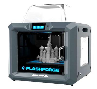
To design a product either physical or digital model it is necessarytofocusontheend to enddesignparametersof the product. Research showed that the components that weredesignedwereanendproductandwerenottestedfor their dimensional accuracy. Therefore, a product is being designedanddevelopedsoastocoverallthedimensional aspects of the product like flat, inclined, curved surface having concave and convex structures. Fig 3.2 shows the component design for all the above stated design parameters.
InAdditiveManufacturing(AM),surfacefinishandtexture can determine the quality of the end product. Fundamentally,3DtechnologyunderFDMisprimarilybased onlayermanufacturingprocesses[19].SurfaceRoughness canoftenbedefinedastheshorterfrequencyofthesurface relative to the troughs [20]. The surface is rough if the presentdeviationsarelarge;itissmoothifthedeviationsare small.Roughnessalsohelps in governing how theprinted object interacts with the environment. Under certain circumstances, high roughness aids in enhanced adhesion [21]. Often highly rough surfaces are undesirable as they maybehardtocontrolundermanufacturing,forinstancein theFDMprocess[22].Beingveryvital,theroughnesscanbe calculated using multiple methods based on different processesandvariedrequirements.Surfaceroughnesscan be calculated using the Arithmetical Mean Height system (Ra).Raconsiderstheaverageoftheabsolutevaluesalong the roughness sample length [23]. Among many other methodsused,thisone,inparticular,holdsmeritasitmakes useoftheISOstandardofmeasuringthemeanlinesystem [24].Raismeasuredinmicroinchormicrometer.
Amplitude parameters are another class of measurement thatclassifiesvariousapproachestocalculatetheroughness ofthematerial.Itallowsdeterminingtheroughnessbased on vertical deviations present in the profile. This class includesmethodslikeArithmeticMeanDeviation(Ra),Root MeanSquare(Rq,Rms),Skewness(Rsk),Kurtosis(Rku),and Height of Peak, Valleyandtheir ratio (Rv,Rp,Rz) [25,26]. Generally,cross scalecharacteristicslikesurfacefractality, instead of scale specific characteristics, offer more significantpredictionsofmechanicalinteractionsatsurfaces, likecontactstiffnessandstaticfriction[27].Thesemethods helpgreatlyindeterminingtheroughnessandtextureofthe surface using various amounts of dataavailable. Various works have been published wherein the different input parameters were used to observe the changes in the final surfaceoutput[28].Also,theprintingparameterspreviously mentioned like infill density, layer thickness have a considerable effect towards the finish and surface quality [29].
International Research Journal of Engineering and Technology (IRJET) e ISSN: 2395 0056
Volume: 09 Issue: 06| June 2022 www.irjet.net p ISSN: 2395 0072
Roughnesscanbemeasuredbymanualcomparisonusinga comparator.However,ageneralmethodofmeasurementfor sample profile is done by Profilometer [30]. Various measuringinstrumentsareusedtodeterminetheroughness oftheprintedmaterialpractically.Thesearesegregatedinto twopartsmajorly:Contact typeandnon Contacttype.The contact type has instruments like Roughness Tester and AtomicForceMicroscopewhichprovidearesolution1 0.1 nm.Contacttypeoftenhasapoorangularcharacteristicand the positioning of the device may be optional. The Non Contact type consists of instruments like White Light Inferometer and Laser Microscope. They are very strong instruments to measure the roughness, with a resolution scopeoflessthan0.1nm.Theyhavebuilt incamerasystem alongwithgoodangularcharacteristic.Samplesassmallas 10 micrometer to a few milimeters in thickness can be analyzed[31].
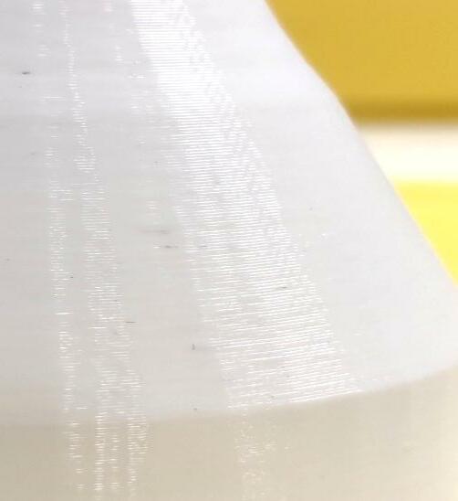
Thestudyshowsthatresearchisdoneonvariousadditive manufacturingtechnologieslikeSLS,SLAetc.butthereisa lotofimprovementrequiredintheproductqualityofFDM technology.Generally,FDMisconsideredtobeslowerthan otherRPtechniqueslikeSLSwhichmaydirectlyaffectthe strength of the product. Another drawback of FDM is the staircase effect.Asweknow,theFDMtechnologyuseslayer by layer manufacturing while building the part; this may createsomesurfaceinaccuracies.Whenacurvedgeometry is created in 3D CAD modeling software, it loses its geometrical accuracy while printing the part because the partisprintedintwoandahalfdimensionalform.Thisloss ofinformationleadsingenerationofastair likestructureon the part. This structure is known as staircase effect. It is negligibleincaseofperpendicularandhorizontalsurfaces, butitseffectismaximumininclinedorcurvedsurfaces.
Figure3.4showstheeffectofthestaircaseinRPprocesses. The effect can be decreased by decreasing the layer thicknessbutthismightleadtoincreaseinthebuilttimeand cost. Therefore, by electing an optimal value of layer thickness one can balance the build time and stair case effect
Fig 3:Imageofthecomponentshowingstaircaseeffect (LayerThickness=0.2mm)
4.1 Component and Machine Specification: Table -2:ComponentandMachineSpecification
MachineType GuiderIISSeries Material PLA InfillDensity 0% InfillPattern Hexagon PrintSpeed 60mm/s TravelSpeed 80mm/s ExtruderTemperature 210:C PlatformTemperature 30:C Orientation 0:
Thedimensionalaccuracyofthecomponentswascalculated usingaverniercaliper.TheVernierwasfirsttestedforno zeroerrorandwasfoundtobecalibrated.Furtherreadings ofallthecomponentsatdifferentinstancesweremeasured andnoted.ThevernierusedduringthetestingwasFlatand Knife Edge Vernier Calliper for measurement of external diameterofthecircularedgeandcurvededge. Inadditionto it,itwasusedforcheckingthethicknessofraftaswellasthe overalllengthofthecomponent.Whereasfortestingofthe weight,ananalyticalweightbalancewasused.
Oneoftheimportantmechanicalparametersisroughness anditisgenerallycarriedouttospecifyforanysurface.More the surface rough, more will be the chances of cracks and
International Research Journal of Engineering and Technology (IRJET) e ISSN: 2395 0056
Volume: 09 Issue: 06| June 2022 www.irjet.net p ISSN: 2395 0072
corrosion,butitcanalsoleadtoadhesionasfarasadditive manufacturingisconsidered.Asurfaceroughnesstesteris usedtoaccuratelyandquicklydeterminethetextureofthe surface and/or roughness of the material. A surface roughnesstestershowsthevaluesofmeanroughnessvalues (Ra)aswellasmeasuredroughnessdepth(Rz)depending on the type of component. The values are usually in micrometer(mm)ormicrons(µm).Thesurfaceroughness testerusedinthisexperimentationwasTimeTR200.
Table 3:Dimensionalaccuracymeasurements
Observation Number 1 2 3 4
LayerThickness (mm) 0.2 0.25 0.3 0.35
DesignedBase Diameter(mm) 50 50 50 50
ActualBase Diameter(mm) 49.8 49.7 49.8 50
DesignedCrown Diameter(mm) 31.6 31.6 31.6 31.6
ActualCrown Diameter(mm) 31.5 31.54 31.6 31.6
DesignedLength (mm) 121.55 121.55 121.55 121.55
ActualLength(mm) 121.72 121.7 121.7 121.76
DesignedWeight(g) 17.95 18.38 18.87 20.05
ActualWeight(g) 16.5 17 17.5 18.5
Time(min) 79 68 69 59
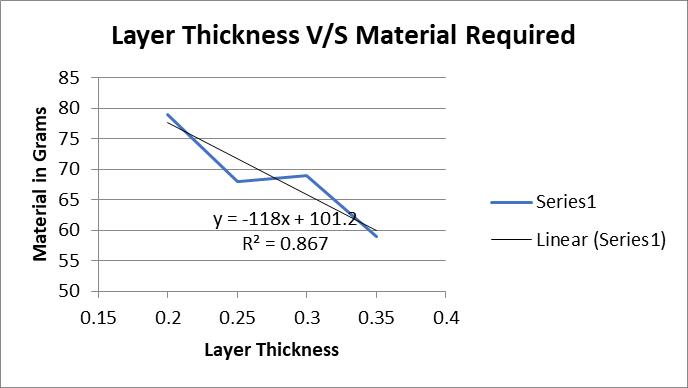
MaterialRequired (m) 79 68 69 59
Chart 2:DeflectioninCrownDiameter
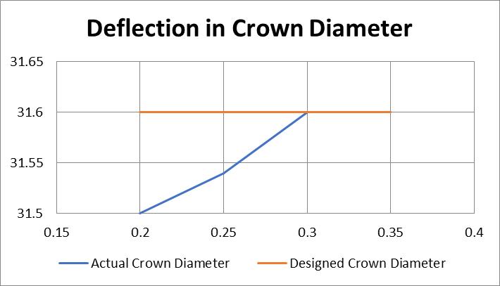
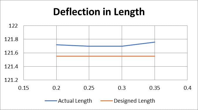
Chart -3:DeflectioninLength
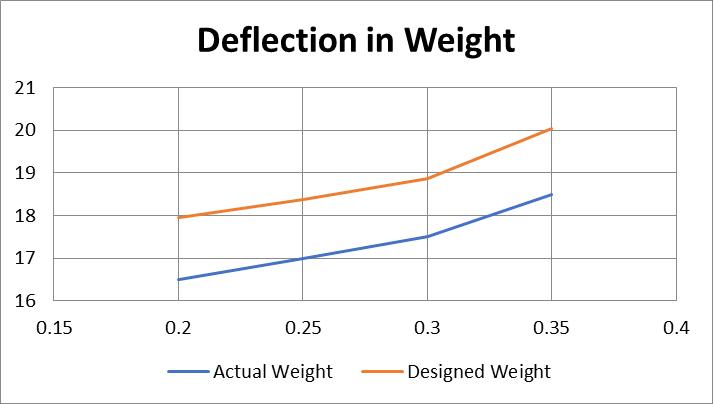
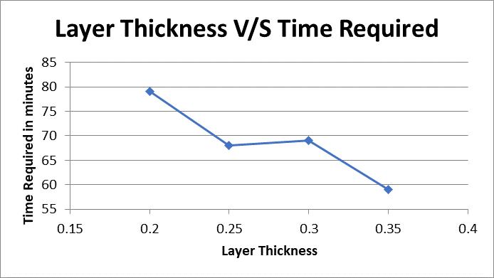
Chart -1:DeflectioninBaseDiameter
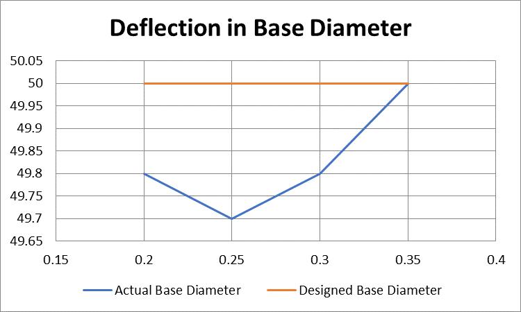
Chart -4:DeflectioninWeight
Chart -5:LayerThicknessvs.TimeRequired
2022, IRJET | Impact Factor value: 7.529 | ISO 9001:2008 Certified
International Research Journal of Engineering and Technology (IRJET) e ISSN: 2395 0056
Volume: 09 Issue: 06| June 2022 www.irjet.net p ISSN: 2395 0072
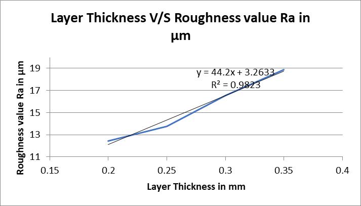
Secondly, the specimen was tested in a surface roughness testerwhichprovidedtheRavalues,whichwerecalculated andplottedonthegraphoflayerthicknessversusroughness value.Thisgraphshowedthatthecurveislinearinnature thatisasthelayerthicknessincreasestheroughnessvalue increases. However by decreasing the layer thickness the roughnessofthecomponentcanbemaintained.
Chart 6:LayerThicknessvs.MaterialRequired
[1] Vosynek, P., Navrat, T., Krejbychova, A., & Palousek, D. (2018). Influence of process parameters of printing on mechanicalpropertiesofplasticpartsproducedbyFDM3D printingtechnology.In MATEC WebofConferences (Vol.237, p.02014).EDPSciences.
[2]HonK.K.B.(2007).“Digitaladditivemanufacturing:from rapidprototypingtorapidmanufacturing”.In Proceedings of the 35th International MATADOR Conference (pp. 337 340).Springer,London.
[3] Sood A. K., Ohdar, R. K., and Mahapatra, S. S. (2012). “Experimentalinvestigationandempirical modellingofFDM processforcompressivestrengthimprovement”.Journalof AdvancedResearch,3(1), 81 90.
Chart 7:LayerThicknessvs.Roughnessvalue
5.2 Surface Roughness
Table 4: SurfaceRoughness
Layer Thickness in mm Roughness Values (Ra) in µm 1 2 3 Average 0.2 12.36 12.54 12.45 12.45 0.25 13.71 13.38 14.22 13.77 0.3 16.69 16.53 16.49 16.57 0.35 18.36 19.67 18.62 18.88
Inpresentwork,aspecimenwithlinearangularandcurved componentwasdesigneddevelopedandfabricatedusinga flash forge guider IIs 3D printer. The specimen was built with PLA material with varied layer thickness of 0.2 mm, 0.25 mm, 0.3 mm and 0.35mm. The same specimen were tested for its dimensional accuracy as well as for surface roughnesstesting.Theexperimentallyobtainedresultswere thencomparedforthedeflectionindifferentparametersof thespecimen(likethebasediameterlengthetc)withlayer thicknessanditwasfoundasthelayerthicknessincreases thediameterandthelengthdecreases.
[4] Deng, X., Zeng, Z., Peng, B., Yan, S., & Ke, W. (2018). “Mechanical Properties Optimization of Poly Ether Ether Ketone via Fused Deposition Modeling”. Materials (Basel, Switzerland),11(2),216[5]Rajpurohit,S.R.,&Dave,H.K. (2018).“Effectofprocessparametersontensilestrengthof FDM printed PLApart”.RapidPrototyping Journal,24(8), 1317 1324.
[5]Chalgham, A., Ehrmann, A., & Wickenkamp, I. (2021). MechanicalpropertiesofFDMprintedPLAparts beforeand afterthermaltreatment. Polymers, 13(8),1239.
[6] Deger K. O., & Deger A. H. (2012). “An application of mathematical tessellation method in interior designing”. Procedia SocialandBehavioralSciences,51,249 256.
[7]Iancu,C.(2018).ABOUT3DPRINTINGFILEFORMATS. Annals of the Constantin Brancusi University of Targu Jiu Letters & Social Sciences Series
[8] Attene, M. (2018). As exact as possible repair of unprintableSTLfiles. Rapid Prototyping Journal
[9] Wohler, T. (1992). “CAD meets rapid prototyping”. Computer AidedEngineering,Vol.11,No.4
[10] Kai C.C. and Fai L.K. (1997). “Rapid prototyping principles and applications in manufacturing”. World ScientificPublishingCo.,Inc.
[11] Muthu S., Senthilkannan S. and Mahesh M. (2016). “Handbook of sustainability in additive manufacturing”. (Vol.1,pp.31 42).HongKong:Springer.
International Research Journal of Engineering and Technology (IRJET) e ISSN: 2395 0056 Volume: 09 Issue: 06| June 2022 www.irjet.net p ISSN: 2395 0072
[12]Shuib,S.,Azemi,M.A.,MohdArrif,I.,&Hamizan,N.S. (2021).Designforadditivemanufacturingandfiniteelement analysis for high flexion total knee replacement (TKR).JournalofMechanicalEngineering(JMechE),8(2),97 110.
[13]Srivastava,M.,&Rathee,S.(2018).OptimisationofFDM process parameters by Taguchi method for imparting customisedpropertiestocomponents. Virtual and Physical Prototyping, 13(3),203 210.
[14]Mohamed,O.A.,Masood,S.H.,&Bhowmik,J.L.(2015). Optimization of fused deposition modeling process parameters: a review of current research and future prospects. Advances in manufacturing, 3(1),42 53.
[15]C.M.Cheah,C.K.Chua,C.W.Lee,C.FengandK.Totong, Int.J.Adv.Manuf.Technol.25,308 320(2005)
[16] Murugan, R., Mitilesh, R. N., & Singamneni, S. (2019). Influence of process parameters on the mechanical behaviour and processing time of 3D printing. Int J Mod ManufTechnol,1(1),21 27.
[17] Jafferson, J. M., & Chatterjee, D. (2021). A review on polymeric materials in additive manufacturing.Materials Today:Proceedings,46,1349 1365.
[18]Dhawale,N.M.,Chavan,N.R.,Patil,D.A.,&Kumbhar,S. M. (2022). 3D Printing Technology and its Applications in Real World Scenario.International Journal of Innovative Research in Science, Engineering and Technology (IJIRSET),11,1167 1174.
[19] Ahn, D., et al. (2009) Representation of Surface Roughness in Fused Deposition Modeling. Journal of Materials Processing Technology, 209, 5593 5600. https://doi.org/10.1016/j.jmatprotec.2009.05.016
[20] Keyence.com. 2022. What Is Surface Roughness? | Introduction To Roughness | Introduction To Roughness | KEYENCEAmerica.
[21] Wikipedia contributors. (2021, October 27). Surface roughness.InWikipedia,TheFreeEncyclopedia.Retrieved 17:59, January 20, 2022, from https://en.wikipedia.org/w/index.php?title=Surface_roughn ess&oldid=1052160253
[22]Taufik,Mohammad;Jain,PrashantK.(2016)."AStudy ofBuildEdgeProfileforPredictionofSurfaceRoughnessin Fused Deposition Modeling". Journal of Manufacturing ScienceandEngineering.138(6).doi:10.1115/1.4032193
[23] Keyence.com. 2022. What Is Surface Roughness? | Introduction To Roughness | Introduction To Roughness | KEYENCEAmerica.
[24]BSENISO4287:2000,Geometricalproductspecification (GPS).Surfacetexture.Profilemethod.Terms,definitions,, andsurfacetextureparameters.
[25] Whitehouse, David (2012). Surfaces and their Measurement.Boston:Butterworth Heinemann.ISBN978 0080972015
[26]Degarmo,E. Paul;Black,J.; Kohser,RonaldA.(2003), MaterialsandProcessesinManufacturing(9thed.),Wiley,p. 223,ISBN0 471 65653 4
[27]Hanaor,D.;Gan,Y.;Einav,I.(2016). "Staticfrictionat fractal interfaces". Tribology International. 93: 229 238. arXiv:2106.01473 doi:10.1016/j.triboint.2015.09.016 S2CID51900923.
[28]J.Jiang,J.Lou,andG.Hu,‘Effectofsupportonprinted propertiesinfuseddepositionmodelingprocesses’,Virtual Phys. Prototyp., vol. 0, no. 0, pp. 1 8, 2019, DOI: 10.1080/17452759.2019.1568835.
[29] H. R. Dana, F. Barbe, L. Delbreilh, M. Ben Azzouna, A. Guillet,andT.Breteau,‘Polymeradditivemanufacturingof ABSstructure:Influenceofprintingdirectiononmechanical properties’, vol. 44, no. June, pp. 288 298, 2019, DOI: 10.1016/j.jmapro.2019.06.015.
[30]4.Abittalkabout"Roughness"|VectorMagnetsNews. www.vectormagnets.com. http://www.vectormagnets.com/n1853721/A bit talk about Roughness.htm.Published2022.AccessedJanuary20, 2022.
[31] Keyence.com. 2022. Side By Side Comparison Of RoughnessMeasuringInstruments|InstrumentsUsedFor Roughness Measurements | Introduction To Roughness | KEYENCEAmerica.
2022, IRJET | Impact Factor value: 7.529 | ISO 9001:2008 Certified Journal