International Research Journal of Engineering and Technology (IRJET) e ISSN:2395 0056

Volume: 09 Issue: 06 | June 2022 www.irjet.net p ISSN:2395 0072
International Research Journal of Engineering and Technology (IRJET) e ISSN:2395 0056
Volume: 09 Issue: 06 | June 2022 www.irjet.net p ISSN:2395 0072
1,2,3 Department of Civil Engineering, United Institute of Technology, Prayagraj, Uttar Pradesh, India. 4 Department of Civil Engineering, Kamala Nehru Institute of Technology, Sultanpur, Uttar Pradesh, India. ***
1. Abstract:
Sewage is waste come from houses, factories etc. as a result of laundry, using the bathroom and all soapy water. Rainwater entering drains and industries, also comeunderthiscategory.
The major aim behind project is to treat sewage at societylevel.Herebasicallywetakesewagefromsociety and return the treated sewage in form of water so that the people of society can use that water for various purpose like washing cloth, vehicles, use in toilet, gardening and various purposes instead of drinking and cooking.
SEWAGE TREATMENT PLANT is a facility designed to receive the wastewater and treated it such a way to make it suitable for human consumption and a waste is used as manure after further treatment in fields for growingcropsetc.
Keywords:Effluent,coagulation,chlorinationetc.
Sewage basically contains water and solid wasteforthetreatmentofthesesewagesweconstructa sewagetreatmentplant(STP).Theprioractivityorwork of STP is to treat the sewage that originate from home andinreturnprovideatreatedwaterthatpeopleusefor variouspurposes.
Now a days many countries updated the tertiary treatment process of STP and make the water suitable fordrinkingandcookingalso.
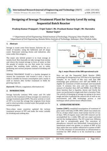
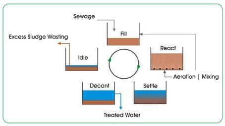
Here we opt the Sequential Batch Reactor (SBR) technologyfordesigningofourSTPthatisforApartment Complex. As we aware of this very well that SBR technology gain proficiency over ASP and MBBR. It is eligible for treatment of both municipal and household waste. It contains less area and also required less amount of chamber than ASP and MBBR. As in SBR the three function that is Equalize, Aerate and Clarify the waterareperformedinsingletankthatisAerationTank. The activity of dumping of sewage are going to be more tough and also it polluted the natural soil as well as our environment and SBR technology proves a real techniquewhichachievelowereffluentlimits.
Lamine (2007) completed investigation of treatment of greywaterwithhelpofSBR.HRTswhichwasnotedwas 0.6 no. of days what’s more, load variety was for 2.5 no. of days. of organic issue with COD removal can be accomplished by a viably SBR and can expel nutrients and do the biodegradation. The SVI noted was 100ml/g and that is exceptionally good. The execution of phosphorus removal was diminished. Concentration of ammonium noted was greater in system of HRT of 0.6 dayswhilethatwassmallerinfluencedinsystemofHRT of 2.5.The situation of concentration as advancement is essential for HRT which is to be received by a load variety.
International Research Journal of Engineering and Technology (IRJET) e ISSN:2395 0056
Volume: 09 Issue: 06 | June 2022 www.irjet.net p ISSN:2395 0072
Moawada et. Al. (2009) researched the ability to treat municipal sewage with a combined method of aerobic and anaerobic treatment forms for example a flowing upward Anaerobic Sludge Blanket (UASB) trailed along aerobic SBR discharge sewage reasonable for supplying watertofields.
3trialsaretested,thatcomprisesof3 4hoursvarietyto HRT of USAB, 6 12 hours period variation of SBR which comprises of aeration cycle variety from 2 9 hours. The increment in hydraulic retention time of a SBR system was useful on Total Nitrogen extraction yet having no impact on Total Phosphorous just as extraction efficiencies of COD and BOD. COD shows removal efficiency as and BOD shows removal efficiencyas andTSSremovalefficiencywas to individually which inferred that utilization of SBRafterUASBisaexcellentinnovation.
The main purpose of sewage treatment plant premise is tocleanthesewageandsupplythatcleanedwatertothe people so that they can utilize that for completing their basicneedsofwaterexceptcookinganddrinking.
Here we design this system on Sequencing Batch Reactor, (SBR) technology which gains proficiency over(ASP) and(MBBR) in many aspects. SBR works on the concept of batch reactor that is in this multiple processdoneinsingletank(aerationtank)inbatchwise meansoneafterother.
A remarkable difference between SBR and traditional activatedsludgesystemwithacontinuousflow,isthatin SBREqualize,aerateandclarifythewaterareperformed insingletankwhereasinASPindividualtankisrequired for every process and functions. In this way SBR requiredlessspaceandalsoeconomicalthanothers.
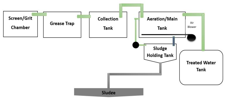
The sewage treatment process includesvariety of knotty functionsanditsscopeoftreatmentmainlydecidedbyits initial nature of influents ofuntested sewage as well as required nature of the effluents. The various treatment methodsofSTPare:
PrimaryTreatment:Inthistypeoftreatmentlargesized suspended solids of organic nature are removed. It this mainlyScreeningtankandOilandGreasetankcome.
Secondary Treatment: The effluent that came out from primary treatment can be further treated out through biological degradation of organic matter. This biological decomposition is performed in two different ways, aerobically and an aerobically. In this usually collection tankandaerationtankcame.
Tertiary Treatment: This is the final step in sewage treatmentprocessinthisweobtainedatreatedwater in the treated water tank and the residue remain moved towardsasludgeholdingtank
a) Thegeneratedsewageisatmost80KLD.
b) The water we obtained after treatment should be used in toilets, washing clothes, vehicles, house and used in small field and garden of apartment, almost mostoftheworkexceptdrinkingandcooking.
c) Based on plandesign a sewage treatment plant of 100 KLD capacity which contains tank or chamber named as bar screen chamber, oil and grease tank, collection tank, aeration chamber, treatment chamberandresidue(sludge)holdingtank.
d) Constructing of STPs done in such a way that it should be far from crowded area in order to avoid inconvenienceduetobadodourofsewage.
e) Here we design a small capacity STPs and also for few numbersof peopleinordertoclean thesewage day by day which reduces extra hold on untreated sewageandfreefromspreadingofvariousdiseases.
f) Capability of treatment of sewage by STPs is such a waythatitfullfilleverydayrequirementofwaterof people so that the dependency of people on groundwaterisreduces.
g) AsallsewagemovedonSTPplantsoitalsoreduces environmentpollutionatverylargeextent.
h) All the treated unit that are design should be economicalandeasytocleanandmaintainit.
International Research Journal of Engineering and Technology (IRJET) e ISSN:2395 0056
Volume: 09 Issue: 06 | June 2022 www.irjet.net p ISSN:2395 0072
6.1. Some important components of projects:
Table 1: Thesilentcomponentsoftheprojectlayoutare describedbelow:
Project’sType SocietyLevel
Watersource Undergroundwater No.ofpeople 500 600 WaterconsumptioninKLD 72KLD QuantityofsewageinKLD 64KLD Proposed sewage with designdetails 80KLD
6.2. Water consumption details [2]
Requirement of water isdependent on the rulesofNBC. The quantity of water required for the proposed project isassessedtobeabout72KLDduringtheactivitystage.
Therequiredwateris=120×600 =72000litre/day
Assume oftotalsuppliedwaterbecomesewage, Theamountofsewagegenerated=72000×0.8 =57600litre/day
Takeadetentiontimeas24hours, The quantity(capacity) of sewage produced during this period =57600×( ) =57600litres
Now the sludge is deposited at the rate of40 litres/capita/year:and,assumetheintervalofcleanseis3 months,
Thesludgedepositedvolumeis =40×600×( ) =6000lit.
Fullcapacityofthetankis, =capacityofsewage+capacityofsludge =57600+6000
=63600litres
Sewagequantity=63.6KLD
STPproposalwithdesigndetailsis 80 KLD
6.3. Design wastewater quantity and quality: The Primary and Secondary Treatment units are designedfor80KLDflow.
Table 2:Theraweffluentsandtreatedeffluentsquality aspernorms.[2]
Expected Parameter Influents Treated water
AverageBOD 250 300 mg/litre <10mg/litre
AverageCOD 400 650 mg/litre <250mg/litre
Totalsuspendedsolids 250 300 mg/litre <20mg/litre
6.4. Design of screen chamber and receiving bar: Discharge=80KLD=0.00093 /sec
Assumedetentiontime=6minute
Volumeofreceivingchamber
V=0.00093(60×60)=0.335
Chambersize=1.085m×0.5m×1.75m
6.5. Design of coarse screen:
Velocitythrough screen at maximum flow isassumed to be0.45m/sec.
Barspacing(clear)=2.2cm
Averagedischargeofwastewater=0.00093 /sec Peak discharge = ×Peak factor=0.00093×3 = 0.0028 /sec
Ataverageflowvelocityshouldnotexceedto0.45m/sec, Screen’sverticalprojectedareais= = =0.006222 =6222.22
Diameterofscreen=1cm=10mm,Widthofscreen=1.9 cm=19mm,Clearspacing=2.2cm=22mm.[5]
International Research Journal of Engineering and Technology (IRJET) e ISSN:2395 0056
Volume: 09 Issue: 06 | June 2022 www.irjet.net p ISSN:2395 0072
No. of openings = 15, No. of bars = 15 = 14, No. of endsbars/plates=2
So,Totalnumberofbars=16
Totalgrosswidth=0.5m
Assume,depthorheight=0.8,screeninclinedat Dimensionofscreenis:Length=1m,Width=0.5m.
6.6. Designing of oil and grease tank: Discharge=240 /day
= rising velocity removed oily material should not exceed=0.12m/min(assume).
A= =1.4
Providedepthoftankis2m,theratiooflengthandwidth is3:2
Length = 3m, Width = 1m, Height = 2m + 0.25(free board)=2.25m
Dimensionofoilandgreasetank=3m×1m×2.25m
6.7. Designing of collection tank: Designflow(Discharge)=80KLD
Forcollectiontanktakingapeakfactoras1.[2]
Sewagecollectionin1day=80 /day×1day=80
Depthoftank=4m(assume), Area= =20
Thelengthandwidthratio=3:2
Length=5.5m,width=3.65m,Height=4m.
Dimensionofcollectiontank=5.5m×3.65m×4m
Collection tank air required = 0.5 of air/ for tank volume if more than 2 hrs of retention time is to be accumulate=0.5 /Hr[8]
6.8. Design of aeration tank:
6.8.1. Estimation of Aeration Time:
Firstly,wecalculateAerationCycleTime: HereOrganicload: 80 ( ) /day.
Nowcalculateaerationtime, F/M ratio of SBR shifts from maximum as 0.3 to minimumof0.10 [1]
RangeofF/Mratio:0.1 0.3(ForSBR)
Estimationof0.2fordesigncalculation. AcquireratioofF/Mas0.2
Total oxygen required(assume) as 23.2 kg of /kg of BODextracted:23.2 kg/day.
MLSS in reactor = 4000mg/L. HRT (Hydraulic retention time)= ( ) = (Assume50%decantation)
=1.74Hours(say2Hours).
Then the cycle time = 1.74(Aeration) + 0.75(Decantation) + 0.75(Settling) = 3.24 Hours (say 4 Hours)
So,wedesignfor3batchesinoneday(onworkingtime of12hr)
6.8.2. Tank Design: [7][8]
Discharge=80 /day,BOD=300mg/lit.
Tankvolume= = =30
Sludgeaccumulationprovidedis30%andtotalprovided tankvolumeis39 Assumeddepthoftankis3m
Planarea= =13.33
Reactorprovidedof40 effectivevolume+Freeboard, Tanksize:4m×3.5m×3.0(SWD)+0.25mFB.
6.8.3. Requirement Of Oxygen for Aeration Tank: RequiredOxygen=1.5×loadofBOD
=1.5× =10.875Kg/Batch= =2.719Kg/Hr.
Assume transfer efficiency of Oxygen is 3.5% per meter depthofwatercolumn.
Reactor’stotalSWD=3.0m,Overallefficiency=3.0×3.5 =10.50%,Oxygentobesupplied= =25.89Kg/Hr.
Supplied air = Required Oxygen/ (Air density × W/W % ofoxygeninair)=
International Research Journal of Engineering and Technology (IRJET) e ISSN:2395 0056
Volume: 09 Issue: 06 | June 2022 www.irjet.net p ISSN:2395 0072
=80.41 /Hr.
6.8.4. Total Oxygen Required:
Overallrequiredair=Collectiontankair+Aerationtank air=80+80.41 =160.41 /Hr.
Assumeblowerefficiencyas85%= =188.72 /Hr
Compressionfactor(assume)=1.5
TotalVolumeis =125.81 /Hr.
Providedblowercapacityis150 /Hrfactorofsafetyis considered.
6.9. Designing of Treated Water Tank
Discharge=80 /day
There are three batches completed in one day and the decantationtimeis0.75Hr.[4]
Hence =26.67
Assumedepthoftank=2m So,areaofplaneoftank= =15
Thenlengthofthetank=5mandwidthoftankis3m. Theblockwarriorprovidedatthedistanceof1meter. So,thenumberofwarriors=4
SizeofTank:5m×3m×2m+0.25mFB.
5.10. Design of sludge holding tank:
Averageflowofsewage=80KLD=0.08MLD
Total suspended solid = 300 mg/l, Volatile suspended solid = 250 mg/l, Moisture content digested sludge = 87 , Assume 65 removal done in primary settling tank,Freshsludgehaswatercontentof95
Massofsuspendedsolids= =24kg/day
65 solids are removed by primary settling tank = ( )=15.6kg/day
Freshsludgecontains95 watercontent
Drysolidof5kgmake=100kgofwetsludge
15.6kg of dry solid that generated = ( ) kg/day
Assume specific gravity of wet sludge as = 1.02 i.e.,Density=1020kg/
The volume ( ) of raw sludge produced = = 0.305 /day
Thevolumeofdigestedsludge[6] = ( ) /
Assume digested period as 30 days, capacity of digested tankrequired=5.39
Provideddepthof1.5mofcylinderdigestedtank.
Area= =3.59 ,diameteroftank(d)=2.13.
Thedigestiontankiscylindricalshapehaving: Depth = 1.5m, Diameter = 2.13m with hopper of 1.1 slope
5.11. Pumps: [9]
A. Two transfer pumps are providing one is used in workingandanotherisputforemergencycase, Capacity: 5.0 KLH @ 15 m head, Type: Centrifugal pumps
Solidhandlingcapacity:upto10mm Purpose:For pumping the sewage from collection tanktoaerationtank.
B. Onepumpisusedfortransferringsludge. Capacity: 3 KLH/hr @ 15m head, Type: Centrifugal pumps
Solidhandlingcapacity:upto25mm Purpose:Forpumpingsludgefromtheaerationtank tothesludgeholdingtank.
C. TwoFilterfeedpumpsarerequired. Capacity: 5.0 KLH @ 30m head, Type: Centrifugal pumps
Solidhandlingcapacity:upto5mm Purpose: For pumping the treated effluent from the aerationtanktotreatedwatertank.
International Research Journal of Engineering and Technology (IRJET) e ISSN:2395 0056
Volume: 09 Issue: 06 | June 2022 www.irjet.net p ISSN:2395 0072
80 KLD sewage treatment plant is designed for the treatmentof wastegeneratedbyanapartment.Here we implemented a sequential batch reactor (SBR) technologywhichgainaproficiencyoverASPandMBBR inmanyaspects.SBR oxidizethe(BOD),thatdenitrifythe reduced total nitrogen to a permissible limit and nitrify the ammonia. Water that derived from treated water tankisthenchlorinatedsothatitcanbeusedforvarious purposes like washing clothes, vehicle, used in toilets, gardeningandforotheruseexceptcooking,bathingand drinking. Many countries treated the sewage up to drinking level and India is still working on upgrading theirtechnology.
The remaining solid sludge residue is sends to sludge holdingtankwhichcanbeusedasmanureinfields.
Table 3: Treatmentunitanditssizes
S. No. Nameofunit Size inm
1 Coarse screen filterpress 16 bars with 22mm clear spacing, plate size of 1m m
2 Bar screen chamber 1.085 m
3 Oil andGrease tank 3m
4 Collection tank 5.5m
5 Aerationtank
6 Treated water tank
7 Sludge holdingtank Depth = 1.5m, dia. = 2.13m, hopperslope=1.1
[1] Ministry of Housing and Urban Affairs, Government of India, CPHEEO manual on “Sewage and Sewage TreatmentSystem” 2013
[2] FOR BASIC REQUIREMENT FORWATERSUPPLY DRAINAGEANDSANITATION Indian Standard CODE isused(4threvision),1172:1993
[3] Bousselmi L.,Ghrabi A., Lamine M, Biological treatment of grey water using SBR. Desalination 215 127 132,(2007).
[4] Mahmouda U.F., Moawada A., EI Mollaa E., EI Khateebb M.A., Coupling of SBR and UASB reactor for domestic wastewater treatment, Desalination Vol.242pp.325 335,(2009).
[5] Environment Protection department of Bureau of Point and Nonpoint Source Management, ‘Standards design for Sequencing Batch Reactors’, pp. 385 2188 003.
[6] Water Pollution Control Commission New England Interstate, ‘Sequencing Batch Rector Design and OperationalConsideration’,2005.
[7] KulikowskaDorota,KliminkEwa,DrezwickiA.,“ and COD Removal and Sludge Production in SBR Working with or Without Anoxic Phase”. Bioresource Technology Vol. 98, pp. 1426 1432,2007.
[8] Tata McGraw Hill: 4th edition, Metcalf and eddy ‘WastewaterEngineering’,2012.
[9] Source:http://www.irjet.net.