International Research Journal of Engineering and Technology (IRJET) e ISSN: 2395 0056

Volume: 09 Issue: 06 | Jun 2022 www.irjet.net p ISSN: 2395 0072
International Research Journal of Engineering and Technology (IRJET) e ISSN: 2395 0056
Volume: 09 Issue: 06 | Jun 2022 www.irjet.net p ISSN: 2395 0072
4 , D. ESAKU5
1Associate Professor, Department of Mechanical Engineering, Nadimpalli Satyanarayana Raju Institute of Technology, Visakhapatnam, Andhra Pradesh, India 2,3,4,5 Student, Mechanical Engineering, Nadimpalli Satyanarayana Raju Institute of Technology, Visakhapatnam, Andhra Pradesh, India ***
Abstract This research is about analysis of the effects of different Aerodynamic add on devices on the vehicle to reduce drag and make the vehicle fuel efficient. The 3D model is developed in ANSYS Space claim. Computational fluid dynamics (CFD) is performed tounderstandthe effects ofthese add on devices. CFD is performed in ANSYS Fluent module. Drag Coefficient, lift coefficient, drag force and lift force are calculated and compared. The results are analyzed and it was observed that optimized body has better drag coefficient and lift coefficient which helps improving the fuel economy and stability of the car.
Keywords: Aerodynamics,DragCoefficient,LiftCoefficient, Computationalfluiddynamics,Streamlinedbody.
Aerodynamics plays crucial role in Automobile’s performance.Initially,aerodynamicswasusedinracingto increaseperformanceofthe racecarstoincreasetherace pace. But when fuel economy became a factor in road vehiclesduetohighpricesoffuel,automobilemanufacturers startedtomakechangestoroadcarsbymakingthemmore streamlined and adding diffusers to reduce drag and improvefueleconomy.
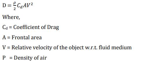
There will be different types of forces acting on a vehicle whenitismoving.Oneoftheforcesthatisactingagainstthe flowofthevehicleisDragForce.Reductionofthisdragforce helps in making a vehicle more fuel efficient and stable vehicle. The basic formula to calculate the overall drag is givenby:
So,ouraimistoreducethedragandliftforcesactingonthe car.Wehaveanalyzed3differentmodels.
Bluffmodel
Streamlinedmodel
Streamlinedmodelwithdiffuser.
Andtheresultswerenotedandduetochangesintheshape ofthecarbodythedragreductionwasobservedwhichin returnwillincreasethefuelefficiencyofthecar.
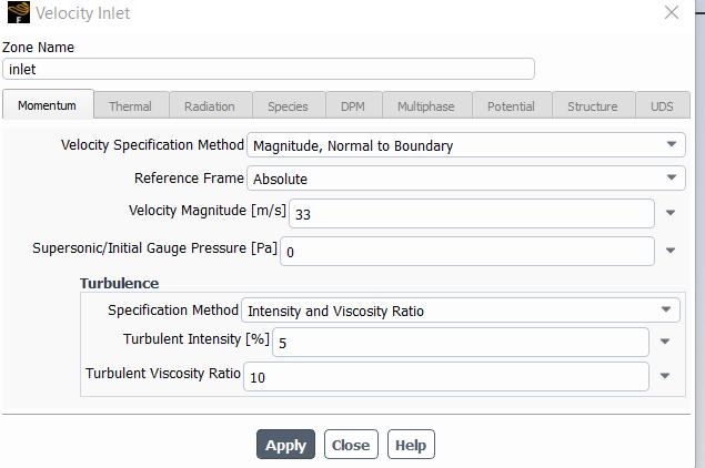
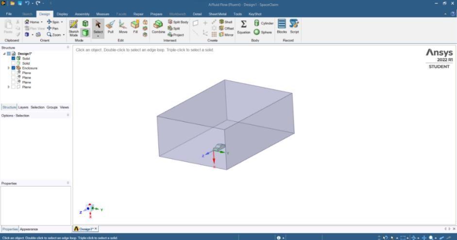
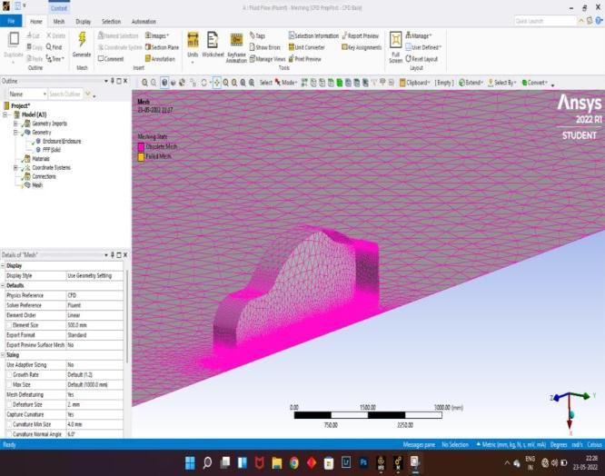
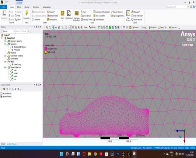
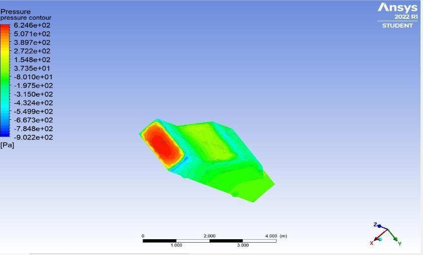
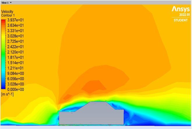
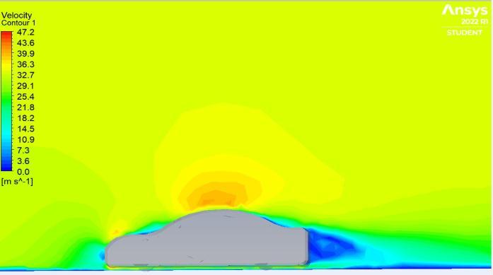
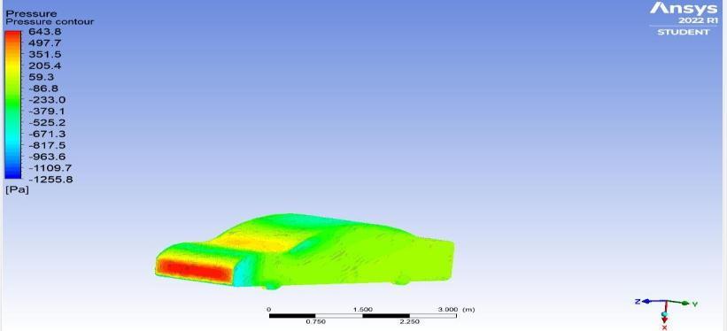
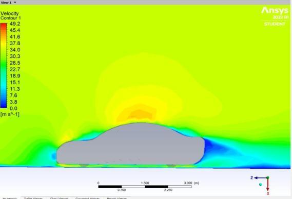
CFD analysisconsists ofthree mainsteps: Pre Processing, ProcessingandPost Processing.Itisusedtosimulatefluid flowusingcomputerswithaccurateresults.Wehaveused ANSYS Space Claim to design the Car models and ANSYS Fluent module to analyze the pressure contour, velocity contour,dragcoefficient,liftcoefficient,dragandliftforces ofthemodels.
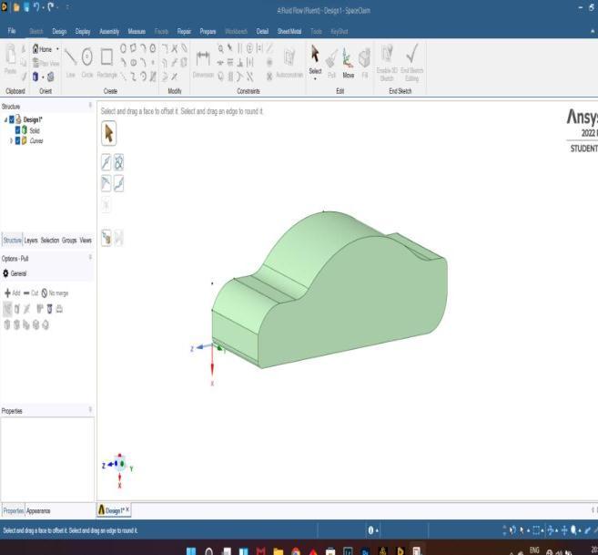
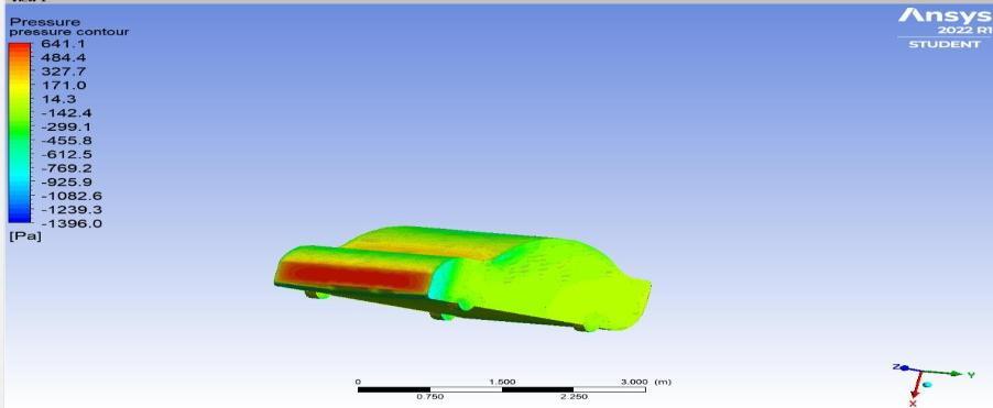
Abodyisstreamlinedwhentheairflowseparationislow whencomparedtoabluffbodywhoseairflowseparationis highwhichcausesalotofpressuredrag.Astreamlinedbody has less pressure drag which in turn results in overall reduction in drag. A stream lined body is sleek and much easiertoforcesuchbodythroughafluid.So,wedesigneda carmodelwithstreamlinedshape.
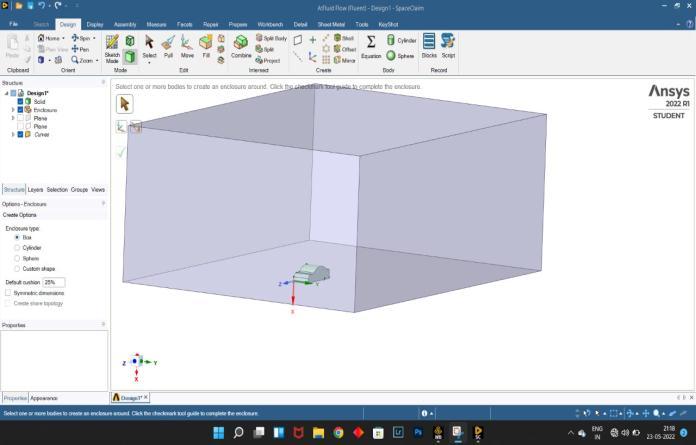
Adiffuser,inanautomobile,isacurvedsectionofthecarrear which improves the car's aerodynamic properties by improvingthetransitionbetweenthehigh velocityairflow underneaththecarandthemuchslowervelocityinambient atmosphere. The aft part of the car is where usually the diffuserislocated.Thediffuserhelpsinmakingtheairflowat the exit is at the same pressure and same speed of the ambient.
International Research Journal of Engineering and Technology (IRJET) e ISSN: 2395 0056
Volume: 09 Issue: 06 | Jun 2022 www.irjet.net p ISSN: 2395 0072
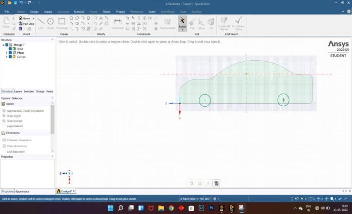
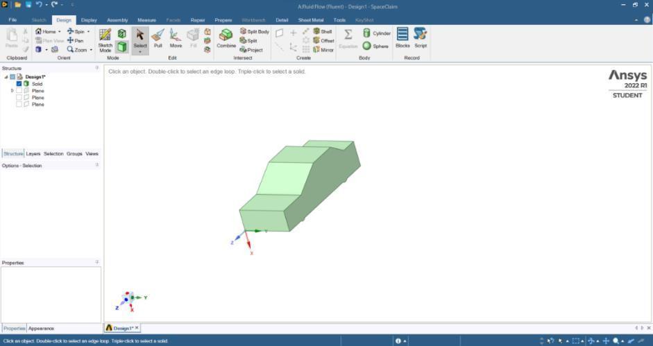
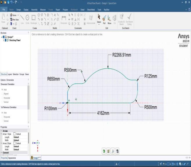
FirsttheBluffmodelwasdesignedandcreatedusingANSYS SpaceClaimsoftware.
International
International Research Journal of Engineering and Technology (IRJET) e ISSN: 2395 0056
Aerodynamic devices. The Drag and lift are improved significantly and result will be better fuel efficiency and betterhighspeedstability.
[1] Koike,M.,Tsunehisa,N.,andNaoki,H.,Researchon AerodynamicDragReductionbyVortexGenerators, Mitsubishi Motors Tech. Rev., vol. 16, pp. 11 16, 2004.
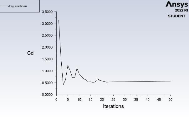
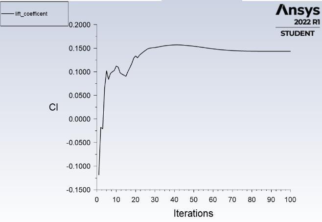
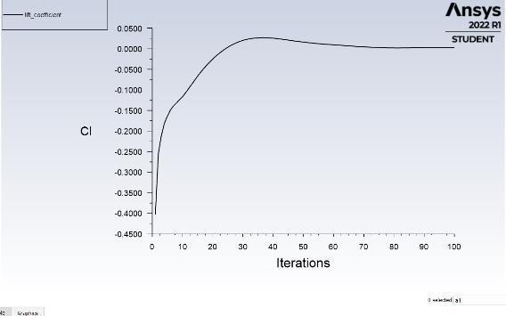
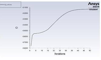
Fig 21:ClPlotofStreamlinedModelwithdiffuser
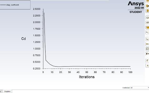
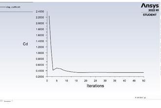
Table 1 contains the values of Coefficient of drag (Cd), Coefficientoflift(Cl),dragforceandLiftForceofallthree models.
Bluff Model Streamlined Model Streamlined Model with Diffuser
Cd 0.5361 0.3242 0.3369 Cl 0.1540 0.0500 0.1000 Drag 1072.98(N) 612.07(N) 634.719(N)
Lift 270.41(N) 4.95(N) 2.615(N)
Table 1
FromtheaboveinformationonthebasisofCd,Cl,Liftand Drag Force the Stream lined model’s drag and lift got significantlyreducedwhencomparedtobluffmodel.Andthe streamlinedmodelwithdiffuser’sliftgotreducedslightly which in return increases the stability of the car at high speeds.So,theoptimizedShapeofstreamlinedmodeland diffuseroffersbetterandlesserdragwhencomparedtothe other models. This helps in Increase of Fuel economy and alsothehighspeedstabilityofthecar.
Fromtheabovestudywearriveatthefollowing:
Aerodynamics is an important factor to consider while manufacturing a vehicle. Here, in this paper, we created a Stream lined model and analyzed the aerodynamic parametersof the carincluding the drag producedduring high performance. From the analysis performed it is observedthatthecar withstreamlinedbody’sdragislow butthereissmallamountofliftisgenerated.Butthediffuser model’s drag is low and also creates small amount of downforcewhichincreasethegripofthecarandprovides goodtraction.Thisanalysisshowsthedifferencebetweena car with no Aerodynamic devices and car equipped with
[2] Singh,S.N.,Rai,L.,Puri,P.,andBhatnagar,A.,Effect ofMovingSurfaceontheAerodynamicDragofRoad Vehicles,Proc.Inst.Mech.Eng.,PartD,(J.Automob. Eng.),vol.219,pp.127 134,2005.
[3] Drag Force and Drag Coefficient, Sadraey M., Aircraft Performance Analysis, VDM Verlag Dr. Müller,2009.
[4] NumericalStudyonAerodynamicDragReduction ofRacingCarsbyS.M.RakibulHassan,ToukirIslam, MohammadAli,Md.QuamrulIslam,ICME2013.
[5] MethodsofReducingVehicleAerodynamicDragby Upendra S. Rohatgi, Presented at the ASME 2012 Summer Heat Transfer Conference, Puerto Rico, USA.
Volume: 09 Issue: 06 | Jun 2022 www.irjet.net p ISSN: 2395 0072 © 2022, IRJET | Impact Factor value: 7.529 | ISO 9001:2008 Certified Journal |