International Research Journal of Engineering and Technology (IRJET) e ISSN: 2395 0056

Volume: 09 Issue: 06 | Jun 2022 www.irjet.net p ISSN: 2395 0072
International Research Journal of Engineering and Technology (IRJET) e ISSN: 2395 0056
Volume: 09 Issue: 06 | Jun 2022 www.irjet.net p ISSN: 2395 0072
1M Tech Structural Engg. Studen, Deptt. Of Civil Engg. Gyan Ganga Inst. Of Tech & Science, Jabalpur, M.P. India.
2Assitant Professor Department of Civil Engineering, Gyan Ganga Inst. Of Tech & Science, Jabalpur, M.P. India.
3Associate Professor Department of Civil Engineering, Gyan Ganga Inst. Of Tech & Science, Jabalpur, M.P. India. ***
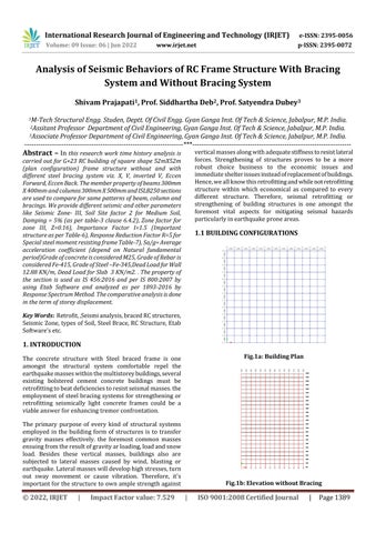
Abstract In this research work time history analysis is carried out for G+23 RC building of square shape 52mX52m (plan configuration) frame structure without and with different steel bracing system viz. X, V, inverted V, Eccen Forward, Eccen Back The member property of beams 300mm X 400mm and columns300mmX500mmandISLB250sections are used to compare for same patterns of beam, column and bracings. We provide different seismic and other parameters like Seismic Zone III, Soil Site factor 2 for Medium Soil, Damping = 5% (as per table 3 clause 6.4.2), Zone factor for zone III, Z=0.16), Importance Factor I=1.5 (Important structure as per Table 6), Response Reduction Factor R=5 for Special steel moment resisting frame Table 7), Sa/g=Average acceleration coefficient (depend on Natural fundamental period)Grade of concrete is considered M25, Grade of Rebar is considered Fe 415, Grade of Steel Fe 345,Dead Load forWall 12.88 KN/m, Dead Load for Slab 3 KN/m2 . The property of the section is used as IS 456:2016 and per IS 800:2007 by using Etab Software and analyzed as per 1893 2016 by Response Spectrum Method. The comparative analysis is done in the term of storey displacement.
Key Words: Retrofit,,Seismianalysis,bracedRCstructures, SeismicZone,typesofSoil,SteelBrace,RCStructure,Etab Software’setc.
The concrete structure with Steel braced frame is one amongst the structural system comfortable repel the earthquakemasseswithinthemultistoreybuildings,several existing bolstered cement concrete buildings must be retrofittingtobeatdeficienciestoresistseismalmasses.the employmentofsteel bracingsystemsforstrengthening or retrofitting seismically light concrete frames could be a viableanswerforenhancingtremorconfrontation.
The primary purpose of every kind of structural systems employed in the building form of structures is to transfer gravity masses effectively. the foremost common masses ensuingfromtheresultofgravityarloading,loadandsnow load. Besides these vertical masses, buildings also are subjected to lateral masses caused by wind, blasting or earthquake.Lateralmasseswilldevelophighstresses,turn out sway movement or cause vibration. Therefore, it's importantforthestructuretoownamplestrengthagainst
verticalmassesalongwithadequatestiffnesstoresistlateral forces. Strengthening of structures proves to be a more robust choice business to the economic issues and immediateshelterissuesinsteadofreplacementofbuildings. Hence,weallknowthisretrofittingandwhilenotretrofitting structure within which economical as compared to every different structure. Therefore, seismal retrofitting or strengthening of building structures is one amongst the foremost vital aspects for mitigating seismal hazards particularlyinearthquakeproneareas.
Fig.1a: Building Plan
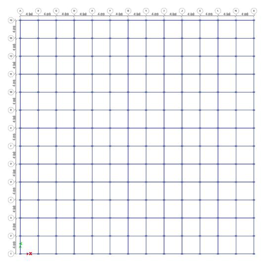
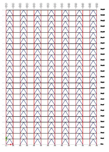
Fig.1b: Elevation without Bracing
International Research Journal of Engineering and Technology (IRJET) e ISSN: 2395 0056
Volume: 09 Issue: 06 | Jun 2022 www.irjet.net p ISSN: 2395 0072
2. ToperformtheResponseSpectrumMethodofanalysison RCstructures.
3.Tocomparethedifferentmodel ofRCstructureswith& withoutsteelbracingsystem.
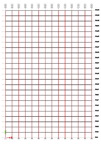
Fig.1c: Elevation with X Bracing
Dheeraj Dheshmukh, Amol Patil, etc al He studied that analysisanddesignedeccentricbracingsystemintall(G+20) steelstructurewithdifferenttypeoflateralloadingbyusing StaadPro.inearthquakezoneIIIwithmediumsoiltype. He selectedthebuildingplansizeof20mX20malongtotheX&Z directionwitheachfloorsof3mandfivebaysof4malongto xandzdirection.Heobservedthatdiagonalbracedsystem havesmallestdisplacement,invertedVbracedsystemhave less base shear as compared to without braced building structures.
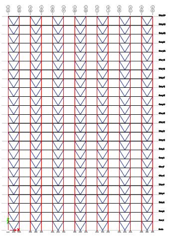
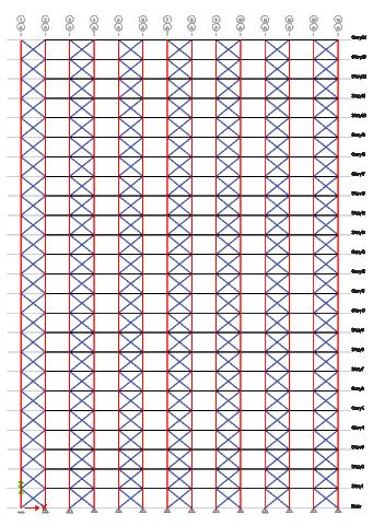
Fig.1d: Elevation with V Bracing
I. Anusha etc al Hestudiedtheanalysisofsteel building frameG+5structureagainsttheseismicloadsanddifferent loadingconditions.Heselected the sixstory buildingfame structurewiththreebaysinlateralandhorizontaldirection andheightofeachfloorwas3mandspacingbetweenbays 8malongtohorizontalwhile6malongthelateraldirection. He also selected different seismic parameters like seismic zoneIII,responsereductionfactor3,importancefacto5and damping ratio five percent. He selected two methods for analysisthestructureasEquivalentstaticloadmethodand response spectrum method and also checked the P delta analysisandconnectiondesignofexteriorandinteriorjoint. He observed different results like story drift, story shear moreinlateralforcedmethodasresponsespectrummethod andDynamicanalysisvaluesaresmallerthanthelateralforce method.
Rishi Mishra, Dr. Abhay Sharma, Dr. Vivek Garg Theyare worked on the G+10 storey RC building framed structure withdifferentbracingsystemlikeXbracing,Kbracing,Vand invertedVbracingsystemandcomparedthethesestructures outputtotheRCbaredframestructuresandtheyworkdone all these models on Staad Pro software to evaluate the structure of a particular type braced system in order to control thelateral displacement,forcesandalsoobserved that inverted V braced system is more economical as comparedtotheotherbracedstructures.
Fig.1e: Elevation with inverted V Bracing
Theobjectiveofthestudycomprisesofthefollowing:
1.Comparativestudyofthebehaviorofdifferenttypeofsteel bracingstructuressuchaswithandwithoutbraced,X,Vand invertedV bracedinRCBuildings.
UsingEtabsSoftware.
2. CreatingModellingofRCbuildingwithoutandwith steelbracingsystem.
3. Applying property like beam, column, slab dimensionandsupporton structure.
2022, IRJET | Impact Factor value: 7.529 | ISO 9001:2008 Certified
International Research Journal of Engineering and Technology (IRJET) e ISSN: 2395 0056
4. ApplyingLoadlikeDeadload,Liveload,seismicload andloadcombination asperIScode.
5. Getting Results in the form of Max Overturning Moments,MaxStory Shears.MaxStoryDisplacement, Max.StoryDriftsetc.
6. ResultsAnalysis:Graphicalanalysisinthetermof Max Overturning Moments, Max Story Shears. Max StoryDisplacement,Max.StoryDriftsetc.
7. ConclusionDiscussion&FutureScope.
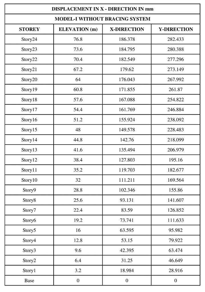
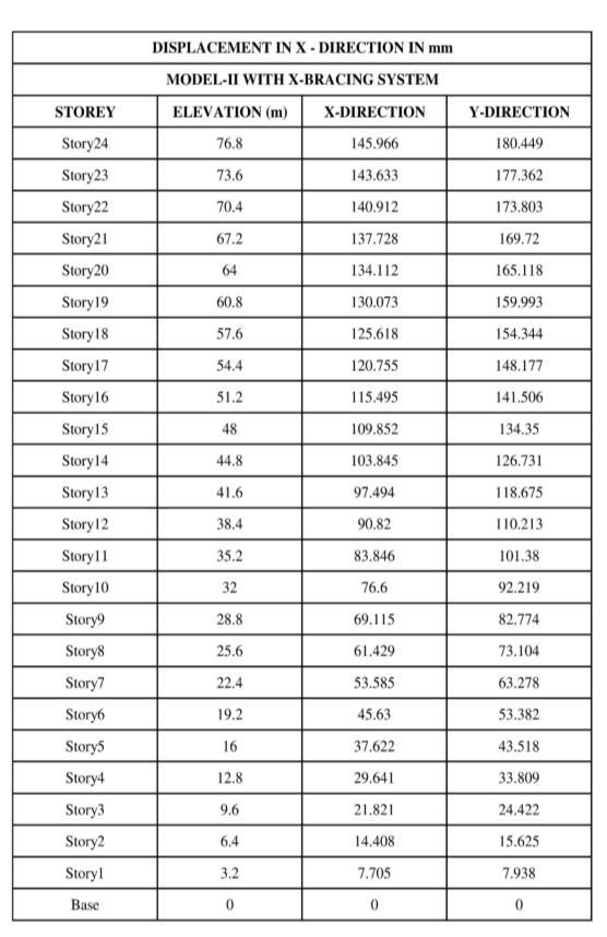
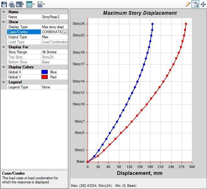
Table:5.1.1StoreyDisplacementsinMODEL I Fig. 5.1.a
Table: 5 1 2 Storey Displacements in MODEL-II
Volume: 09 Issue: 06 | Jun 2022 www.irjet.net p ISSN: 2395 0072 © 2022, IRJET | Impact Factor value: 7.529 | ISO 9001:2008 Certified Journal |
International Research Journal of Engineering and Technology (IRJET) e ISSN: 2395 0056
Volume: 09 Issue: 06 | Jun 2022 www.irjet.net p ISSN: 2395 0072
It is seen that the maximum storey displacement 186.378 mmin X directionand282.433mmin Ydirectionat 24th storey top of the structure in the Model I without bracing system.
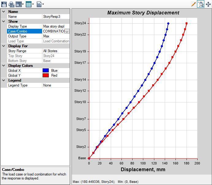
It is seen that the maximum storey displacement 145.966 mmin X directionand180.449mmin Ydirectionat 24th storeyofthestructureandascomparingbothdirectionin whichinydirection,thedisplacementisfoundmaximumin Model IIinwhichthebuildingwithcross(X)bracingsystem.
International Research Journal of Engineering and Technology (IRJET) e ISSN: 2395 0056
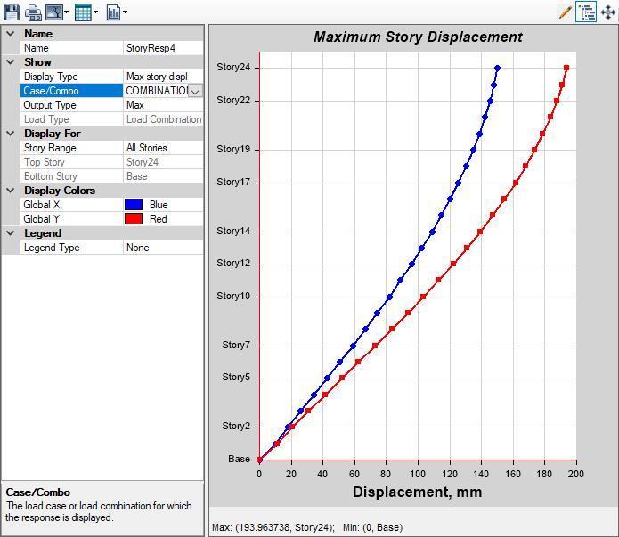
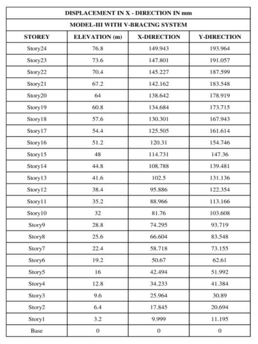
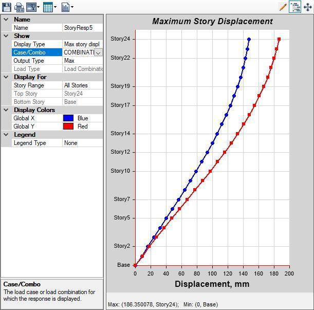
Itisfoundthatthemaximumstoreydisplacement149.943 mminXdirectionand193.964mminYdirectionattopof thestructureinModel IIIwithVbracingsystem.
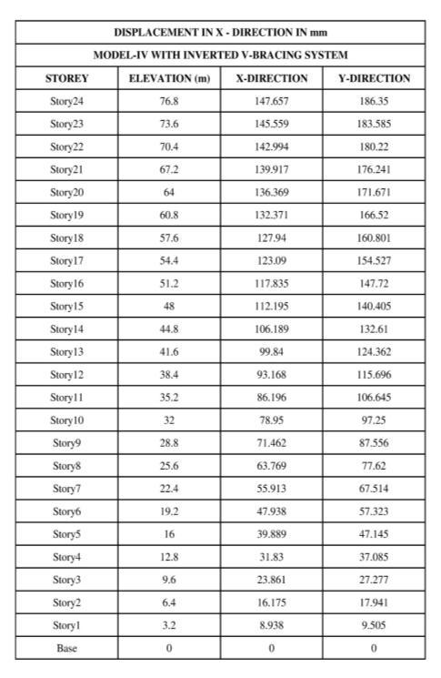
It is seen that the maximum storey displacement 147.657 mminXdirectionand186.350mminYdirectionattopof thestructureinmodel IVwithinvertedVbracingsystem.
[1] Viswanath K.G, Prakash K.B., Anant Desai, “Seismic AnalysisofSteel BracedReinforcedConcrete Frames” InternationalJournalofCivilandStructuralEngineering, Volume1,No1,2010
[2] VenkateshS.V.,H.SharadaBai.,DivyaS.P.,“Responseof a3 Dimensional2X3BaysTenStoreyRCFramewith Steel Bracings as Lateral Load Resisting Systems Subjected To Seismic Load” International Journal of Scientific & Engineering Research Volume 4, Issue 5, May 2013.
[3] Yogendra Singh, “Lateral Load Resisting Systems for MultiStorey Buildings” 4] M.D. Kevadkar, P.B. Kodag, “LateralLoadAnalysisofR.C.CBuilding”,International JournalofModernEngineeringResearch(IJMER),Vol.3, Issue.3,May June.2013
[4] Dr. Vinod Hosur, “Earthquake Resistant Design of Building Structures”, Wiley India Pvt. Ltd, New Delhi, India.
[5] S.K.Duggal,“EarthquakeResistantDesignofStructures”, OxfordUniversityPress.
[6] IS 1893 (Part 1): 2002, “Criteria for Earthquake Resistant Design of Structures”, Bureau of Indian Standards,NewDelhi.
Volume: 09 Issue: 06 | Jun 2022 www.irjet.net p ISSN: 2395 0072 © 2022, IRJET | Impact Factor value: 7.529 | ISO 9001:2008 Certified Journal