International Research Journal of Engineering and Technology (IRJET) e ISSN: 2395 0056

Volume: 09 Issue: 06 | June 2022 www.irjet.net p ISSN: 2395 0072

International Research Journal of Engineering and Technology (IRJET) e ISSN: 2395 0056
Volume: 09 Issue: 06 | June 2022 www.irjet.net p ISSN: 2395 0072
1Assistant Professor
ACE Engineering College, Dept of Electrical and Electronics Engineering, Telangana, India 2, 3, 4 Student of ACE Engineering College, Dept of Electrical and Electronics engineering, Telangana, India ***
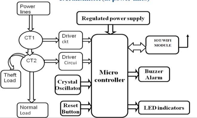
Abstract: Power theft is that the biggest problem nowadays, which causes huge loss to electricity boards. And to hide these losses ultimately, price is increased. So ifwe are able to prevent these thefts, we are able to save lot of power. By keeping track of electricity used, you identify where the best opportunity for energy savings lies. Becoming responsive to overall energy use involves keeping track of the readings on the electrical meter. The traditional practice for power theft is to tag the wires to feeder lines for field motors power/etc. So, by sensing current flow through the load & energy feedback we will prevent power theft employing a breaker. During this system, a micro controller is interfaced with power line/feeder with current sensors using simple current sensing circuit, Wi Fi communication link, & a contactor to form or break line. At the sub station end, a PC is connected with a Wi Fi link to speak with all energy meters & a buzzer. In normal condition, micro controller reads current value/ratio in feeder lines continuously. If the microcontroller gets both current transformer values same, it indicates there's no power theft. Whenever the ability is being theft this technique automatically detects the condition by changing the CT ratio. This method automatically activates device and sendmessage to substation with code. This information is distributed to substation using wireless communication. Within the society it's been observed that several people practice illegal power theft by means of tapings from lines meter bypassing etc. Our project aims to stop, ultimately to scale back the electricity bill charged to the consumers. Our project is to be implemented using Internet of Thing (IoT) in conjunction with Arduino Uno module. Connect Wi Fi to mobile through mobile telnet application.
The'WirelessPowerTheftMonitoringSysteminpowerlines 'projectfocusesondetectingandmonitoringelectricitytheft at power lines. The proposed technology guards against unauthorized use of electricity. The problem of illicit electricity usage can be remedied electronically at this moment in technology advancement. For wireless communication, we employ Wi Fi module Using IoT technologies, this project aims to establish a system for detecting theft This project will employ on distribution systemandinthisprojectweconnecttheWi Fimoduleto mobiletelnetapplicationthroughIPaddressandwecanuse thisapplicationonmobileorlaptopwatchreadingsofload andtheftalertandshowthepowertheftalertondisplay
Electricitytheftisdirectlylinkedtogovernancemetrics,with higheramountsfoundinnationswithpooraccountability, politicalinstability,ineffectivegovernment,andhighlevels ofcorruption.Increasingelectricitygenerationalonewillnot suffice to meet today's demands. So that the generated powerisusedasefficientlyaspossible,powerconsumption andlossesmustbecontinuouslymonitored.Inourcountry, Electrical energy theft runs from 3 to 30%. This illicit electricity usage may have an indirect impact on our country'seconomicsituation.
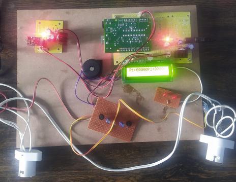
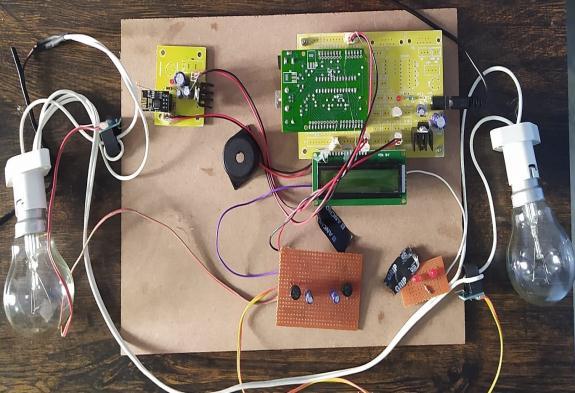
First of all, we need to connect all equipment accordingly block diagram, in this project need to take two power suppliestoprototype,oneisaDCsupply,anACsupply,taking power an adaptor which converts AC to DC supply, this supplyconnecttoArduinoboardAcsupplyisgiventopower line.AfterthatturnonthepowersupplythroughRPS,andthe display is on, After we should connect the Wi Fi in our mobileorlaptop,withtheusernameandpasswordprovided Wi Fi module than in the display we seen the p1 and p2 valuesthisvaluemeasuredbythecurrentsensors,heretwo bulbsrequiredOneisactinglikeanormalloadanotheroneis atheftload,anormalconditionbulb,oneglowsindisplayon theftoccurredonthisline,P1andP2valuesareequal.When thebulb 2isturnedONmeansinthislinehavepowertheft andthep2valueincreasesnotequaltothep1,thengivethe buzzerAndLEDindication,ONdisplayshowingthepower theftandpowertheftinformationsenttomobileorlaptop throughmobileTelnetapplication.Hence,inthisprojecthave apowerline,theloadsarebulb 1andbulb 2herewhenthere isno powertheftonthislineloadvaluesarethesame,the valuearenotsameconsideraspowertheftinthispowerline
2022, IRJET | Impact Factor value: 7.529 | ISO 9001:2008 Certified Journal | Page138
International Research Journal of Engineering and Technology (IRJET) e ISSN: 2395 0056
Volume: 09 Issue: 06 | June 2022 www.irjet.net p ISSN: 2395 0072
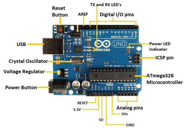
Arduino isamicrocontrollerboardprimarilybasedtotally at the ATmega328P (datasheet). It has 14 virtual input/outputpins(ofwhich6maybeusedasPWMoutputs), 6 analog inputs, a sixteen MHz quartz crystal, a USB connection,astrengthjack,anICSPheader
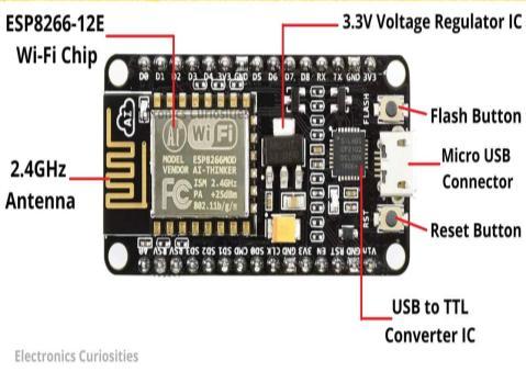
TheWi Fimodule(ESP8266)isacircuitthatisusedtolink anyinternet connecteddevice.Inoursystem,weshoulduse usernameandpasswordtoconnecttheWi Fimoduleinour mobile.The reading will be deliveredto the user's mobile deviceviathisWi Fimodule.TheWi Fimodule'sfrequency rangeistypically2.4GHz.
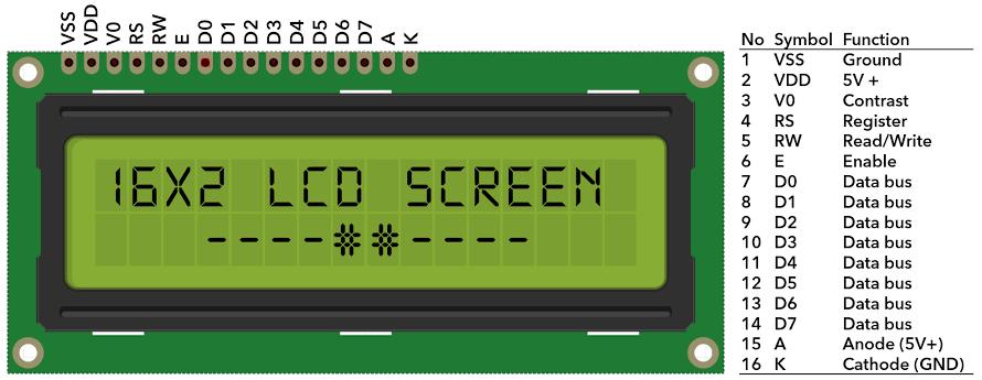
LCDdisplayALCD(Liquidcrystaldisplay)maybeadisplay devicewhichisincrediblythinandflatmadeofanynumber of color or monochrome pixels arrayed before of a lightweightsource.Eachpixelconsistsofacolumnofliquid moleculessuspendedbetweentwotransparentelectrodes and two polarizing filters, the axes of polarity of it are perpendicular to every other. Without liquid crystals between them, light passing through one filter would be blockedbytheopposite.Theliquidtwistspolarizationlight enteringonefiltertopermitittolaborundertheopposite.
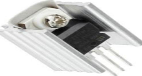
Theheatsinkaheatsinkisacomponentthatabsorbsand dissipates surplus heat. It is connected to the voltage regulator and is used to regulate the amount of heat dissipatedbythevoltageregulator.
International Research Journal of Engineering and Technology (IRJET) e ISSN: 2395 0056
Volume: 09 Issue: 06 | June 2022 www.irjet.net p ISSN: 2395 0072
Theword"buzzer"comesfromtheaddingnoisethatitmade when they were electromechanical bias operated from stepped downAClinevoltageat50to60cycles.Ringora beep sounds are generally used to indicate that a buttons beenpressed.
Start
Power ON Connecttotheload(60w)
Observe the p1 and p2 readings on LCD display
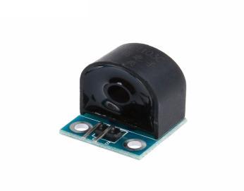
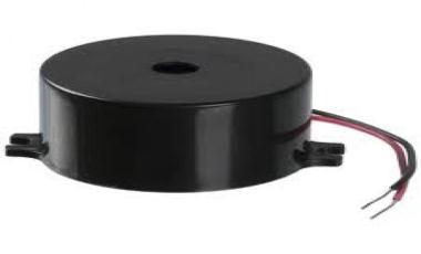
Therearemanydifferenttypesofsensors,eachofwhichis appropriateforagivencurrentrangeandambientcondition. Themostcommonsensoramongtheseisacurrentdetecting resistor. It is a current to voltage converter in which the currentislinearlyconvertedtovoltagebyputtingaresistor intothecurrentchannel.Becausedifferentsensorscanhave distinctfeaturesforanumberofapplications,thetechnology employedbythepresentsensoriscritical.Currentsensors, alsoknownascurrenttransformersorCTs,aredevicesthat usethemagneticfieldto detectthecurrent and provide a proportional output. They can work with both AC and DC power. We can measure current passively with current sensors
Fig 7:Currentsensor
Iftherenochange inreadingsonLCD
DisplaypowertheftonLCD
BuzzerisonandLEDGlowwith RED
Transmitthepowertheft warningmessagetothemobile orlaptop STOP
Fig 8:Flowchart
International Research Journal of Engineering and Technology (IRJET) e ISSN: 2395 0056
Volume: 09 Issue: 06 | June 2022 www.irjet.net p ISSN: 2395 0072
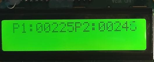
Whentheacsupplyisgiventothepowerline,thedisplay showstheP1andP2values.Here,bulb 1isthenormalload, and bulb 2 is the theft load. Give the supply to the power line;bulb 1isglowing,whichmeansherethereisnotheft involvedinthisline.Voltagereadingsofloadsaredisplayed onthescreen
Theactualresultwasidenticaltowhatwaspredicted.The following operations can be successfully performed by an embeddedsystemthathasbeendevelopedtodetectpower theft.
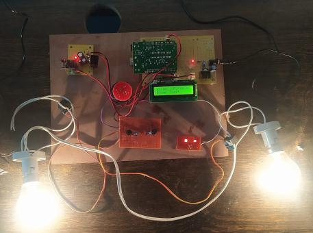
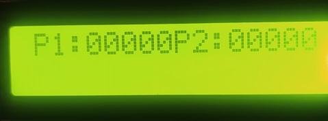
Once the primary tests are achieved, the power supply is giventotheRPSandcontrollerboardthroughtheadaptor. TheLCDdisplayshowsthatP1andP2valuesarezero,and Wi FiisconnectedtothemobilewiththeWi Fimodule.
STAGE-3
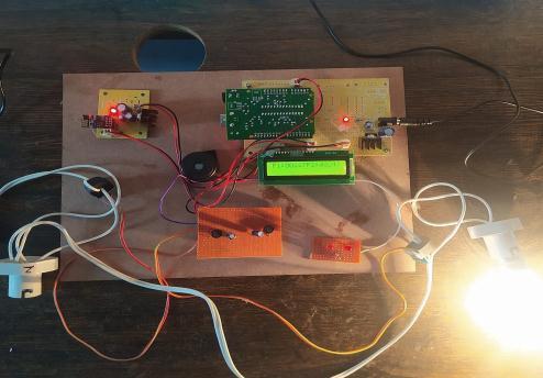
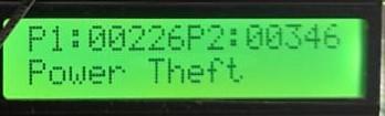
Whenbulb 2isconnectedtothecurrentsensor,itmeasures thecurrentvalueandshowsthereadingsonthedisplay.The P1andP2valuesarenotequal.P2valuesrisebyacertain amount.Itbecomespowertheftinthisline.
When the Power theft is defected in power line and gives warningmessageisontheLCDdisplay,buzzeralarm,and ledindicationsandp2valueisincrease240vto346v,here extra100visdrawnbytheftload.
International Research Journal of Engineering and Technology (IRJET) e ISSN: 2395 0056

Mr.Goutam Barma, Assistant professor, EEE department, ACE Engineering college, Hyderabad. He did his B Tech from N.I.S.T, Berhampur, odisha. and M Tech fromNIT,Warangal
STAGE-5
Senttheftinformationtothemobilethroughthemobile telnetapplication.
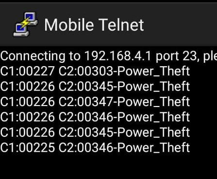
We have made a tiny attempt through this project to compensateforrevenuelossesincurredbyelectricitytheft inourcountry.'WirelessPowerTheftMonitoringSystemAt TheLocalSubstationandthatinformationsenttomobilevia mobiletelnetapplications'provesusefultothepeoplewho useitandhelpsineliminatingillegalusageofelectricityby workingreliablyandsatisfactorily,thussavingtherevenue loss totheelectricitysupplyingauthorityinthelongterm duetopowertheft,asseeninthiswork.
[1] MilanVerle “Architecture&programmingof8051”.
[2] Mazidi, Mazidi, McKinlay “The 8051 microcontroller andEmbeddedSystem.
[3] T. B. Smith, “Electricity theft comparative analysis,” EnergyPolicy,vol.32,pp.2067 2076.
[4] Raj kamal Microcontrollers Architecture, Programming,InterfacingandSystemDesign
[5] MazidiandMazidi EmbeddedSystems.

[6] www.wikipedia.com

Mr.KolimiNareshstudentofEEE department India. He did his Diploma from SS. Government polytechnic college, Zaherabad, sangareddy,pursuingB Techfrom ACE Engineering college, Hyderabad

Mr Muddasani Chanukya Reddy student of EEE department India .He did his diploma from TKR Engineering college, Hyderabad, Pursuing B-Tech from ACE Engineeringcollege,Hyderabad.
Mr. Guguloth Upendar student of EEE department India. He did his intermediatefromshrinidhijunior college, suryapeta, pursuing B Tech from ACE Engineering college,Hyderabad
Volume: 09 Issue: 06 | June 2022 www.irjet.net p ISSN: 2395 0072 © 2022, IRJET | Impact Factor value: 7.529 | ISO 9001:2008 Certified Journal |