1
International Research Journal of Engineering and Technology (IRJET) e ISSN:2395 0056

Volume: 09 Issue: 06 | June 2022 www.irjet.net p ISSN:2395 0072
1
International Research Journal of Engineering and Technology (IRJET) e ISSN:2395 0056
Volume: 09 Issue: 06 | June 2022 www.irjet.net p ISSN:2395 0072
1
Abstract Integralabutmentbridges(IABs)areincreasinglybeingusedtoeliminateundesirable effectsofbridgejoints onthelong termperformanceofbridges.Soil structureinteractionsattheabutmentsoccurringduringloadingofabridge are complex in skewed and long span IABs. The goal of this study was to better understand the complex soil structure interactions that occur in IABs and to develop design guidelines. Horizontal movements of the superstructure cause deformationsintheinfrastructure,resultinginacomplexinteractionwiththesoil.Geotechnicalconcernsmayoccurasa resultofthisinteraction,compromisingthebridge'sandapproachembankments'serviceability.Theoccurrenceofbump attheendofthebridge(adifferenceinsettlementbetweentheabutmentandtheearth)isincreasedinIABsbyreaching the active stress condition during deck contraction. The lateral earth pressure, on the other hand, increases as the deck expands.Ratchetingoccursbehindtheabutmentasaresultofthecyclicstressoftheearth.
Key Words: Integral Abutment Bridges; Soil Structure Interaction; Ratcheting; Effect of K*(Enhanced Lateral Earth PressureduetoSoilRatcheting),MIDASCivil(2019).
Theeffectofsoil structureinteraction(SSI)onthereactionofbridgestructuresisimportant.Despitethebodyofstudy on thesubject,therearestillseveralareasthatremainunclear.Furthermore,designcodesdonotcovermanyaspectsofSSI effectintheirprovisions.IRCSP 115:2018ishasincludedtheeffectofdesignearthpressureonintegralabutmentbridges asperthebasisofEuropeancode(PD 6694 1:2011).
Integralbridgesarecharacterizedbymonolithicconnectionbetweenthedeckandthesubstructure.Thisrigidconnection allowsintegralbridgestoactasasingleunitinresistingthermalandbrakeloads.
The effect of SSI should betakeninto consideration in theanalysisfora better performanceofan integral ridge.All civil engineering structures have at least one structural element in direct contact with the soil. It is vital to consider the response of the soil supporting the structure in order to determine the exact response of the superstructure, which is clearlyexplained inthesoil structureinteractionanalysis.Several studies have foundthatthecomplicated soilstructure relationship in integral bridges poses a significant challenge for engineers in terms of designing and predicting the behavior of integral bridges in use while taking into account the SSI impact. Integral bridge post construction problems are primarily geotechnical in character, not structural. In this project, we will study the effect active, passive and design earthpressureonintegralabutmentbridgesbysoilstructureinteractions.
Anintegralbridgearedefinedashavingnoexpansionjointsorslidingbearings,thedeckiscontinuousacrossthelengthof the bridge. Integral bridges are alternatively referred to as integral abutment bridges, joint less bridges, integral bent bridges and rigid frame bridges. Integral Abutment Bridges are structures where the superstructure and substructure move together to accommodate the required translation and rotation. They span from one abutment over intermediate support to the other abutment, without any joint in deck. Integral bridges are constructed all over the world including India.TheIntegralAbutmentbridgeconceptisbasedonthetheorythatduetotheflexibilityofthepilling,thermalstresses aretransferredtothesubstructurebywayofarigidconnectionbetweenthesuperstructureandsubstructure.
International Research Journal of Engineering and Technology (IRJET) e ISSN:2395 0056
Volume: 09 Issue: 06 | June 2022 www.irjet.net p ISSN:2395 0072
Analysis of soil structure interaction mechanisms on integral abutment bridge (shyam nandan roy1, umesh pendharkar2, raghvendra singh3)Bridges constructed with joints are identified as conventional bridges.Bridgesconstructedwithoutjointsareknownasintegralbridges.Thepresentresearchworkincludesthe analysisof3Dnumericalmodelwith5m highabutments,40mspanlengthand15mlengthpilefoundationwith 0.85 m diameter in the integral bridge using the finite element analysis software MIDAS CIVIL (2011) that simulatethebehaviorsofintegralabutment bridgestoassessthesoil structureinteractionbetweenthepileand soil.Inaddition,thiswork evaluatesandvalidatesthesuitabilityofintegral abutmentbridgesfordifferenttypes of foundation soil by a parametric study under the static loading conditions. The results obtained from the analysis, the vertical displacement estimated in dense sand and soft clay are 6.3 mm and 31.1 mm respectively. ThemaximumpermissibledeformationofgrouppileasperIS:2911,part4,1985is12.0mm
INTEGRAL ABUTMENT BRIDGE A review and comparison of the integral bridge and conventional bridge (amit bamnali1, P.J. Salunke2) nowadaysthemethodsofbridgeconstructionischangingallovertheworld.The new innovative methods are developed and adopted over the traditional construction method as per the requirement of the field and the structural requirement. In this paper introduced a brief understanding of the conceptofintegralabutmentbridgeanditsworking.Wetriedtogiveanideaabouttheprocedureofconstruction of the integral abutment bridge and explains its structural benefits. There are several advantages of the integral abutment bridge over the conventional bridge system they also elaborate on this paper. The paper listed the different types of bridges and different types of the integral abutment bridge. It tries to explain the need of integral abutment bridgein specific areaswhere maintenancecost isway moreand the damages due toleakage andcorrosionofthe bridge componentsisa majorproblem.Thestructural systemhasthepotential tofulfill the requirements and demands of the structural requirement. The paper presents an elaborate comparison of the integralabutmentsystemwiththeconventionalbridgesystem.
Performance analysis of geometrical irregularities of integral type bridge: state of art (meet vora1, abbas jamani2) bridges are very important structures considering the connectivity of road network. The high initial cost,seismic/windvulnerabilityandmaintenanceplayamajorroleinanybridge.IntegralTypeBridgeovercomes thisbyeliminatingexpansionjointandhencebearingtoo.Asthestructureactasasingleunitthereisnomoisture seepage which deteriorates the materials. This bridge is proposed to provide robust configuration against earthquakeshakingandincreasethedurabilityduetoexclusionofjointsandbearings.Theportalframedisperses the loads more evenly and the resulting sections can be more economical and aesthetic. The insight is provided intothebehaviorofthesebridges
Behavior of integral abutment bridge with spring Analysis (1shaikh tausif, 2l.G.Kalurkar)Integralabutment bridges (IAB) are joint less bridges in which the deck is continuous and monolithic with abutment walls, due to this continuity in the bridge the bridge have less expensive, esthetically pleasing appearance, safe riding, economical in construction, prevent the corrosion. To get a better understanding of the behavior of IAB in different situation, a comparative study is carried out on a typical IAB and a simply supported bridge (SSB) of same geometry and loading conditions, and compares these bridges with spring and without spring analysis at bothends.Atotalofthreebridgeswereanalyzedforthisworkbyusingmidascivilsoftware.
Comparative analysis of abutment type integral bridge & simply supported bridge by providing different geometric irregularity (ashish A charaniya1, ankit D prajapati2, aakash R suthar3, abbas R jamani4) the bridge construction methods are changing throughout the world. The new methods are only be accepted based upon the requirement of field & structural aspect. In this paper, we have introduced the concept of abutment integralbridgebyprovidingapierinbetween&comparingit,withconventionalbridge.Therearetotal36model ispreparedfortheresearchwork.The24modelwithoutsoilstructureinteractionforabutmentintegralbridge& simplysupportedbridge(12foreach)ispreparedbaseduponthelength20m,25m&30mwithaskewangleof 15, 30, 45, and 60. The result is displayed in form of graph which is dictated as deflection for moving load, self weight, & temperature. The result in form of bending moment for moving load & self weight are also shown in formofgraph.Thedynamicearthpressureisalsotakenintoaccountandthegraphshowingbendingmomenton abutmentfortheearthpressureisalsopresentedinthisresearchpaper.Theseismicanalysisonabutmentforthis 24 model is also viewed based upon is 1893(part 3) 2014. The 12 model of simply supported bridge which is
International Research Journal of Engineering and Technology (IRJET)
e ISSN:2395 0056
Volume: 09 Issue: 06 | June 2022 www.irjet.net p ISSN:2395 0072
mentionedintheaboveparagraphwithoutpierspringwascomparedwith12modelofsimplysupportedbridge withpierspringforsoilstructureinteractionisprepared.Theresultforthebendingmomentatthebottomofpier formovingloadisshowninformofchart.
StudyIntegralabutmentbridges,advantages&limitationsforpurposeofanalyzing.
StudytheSoil StructureInteractionsaffectingonIntegralAbutmentBridges.
StudytheCoefficientsofLateralEarthPressure.
Study the effect of cyclic loading on the Integral Abutment due to which (K*) Design earth pressure is under consideration,asperEurocode(PD6694 2011)&IRC.SP 115 2018.
StudytheeffectofK*ondifferenttypesofIntegralAbutmentsforanalyzingstressesanditsdeflections.
StudySoilStructureinteractionsofdifferenttypesofsoilsonabutments&pilefoundationsusingspringmethod inMIDASCivil(2019).
To study IRC. SP 115:2018, that includes Integral Abutment Bridges & effect of Soil Structure Interactions, considering(K*)designearthpressureeffectonabutmentsbasedonEuropeancode.
To study about Integral Abutment Bridges, types, advantages & limitations, to introduce design earth pressure (K*)effect.
TostudyaboutSoil StructureInteractionsanditsapplications.
TostudytheCoefficientsofLateralEarthPressure&itsIntermediateValues.
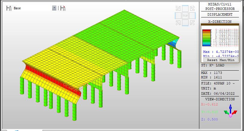
Tostudythecyclicloadingduetoseasonal effect which includesthesoilratcheting phenomenonontheIntegral abutments.
TostudythemethodsofanalysisforpurposeofearthpressureonIntegralabutments.
To study the effect of Active (Ka), Passive (Kp) & Design (K*) earth pressure on different types & sizes of integratedabutments,byusing“Limitequilibriummethods”&“SoilstructureInteractions”.
ToanalaysesoilstructureinteractionofintegralbridgeonMIDASCIVIL(2019).
FollowingresultsobtainedfromtheanalysisofintegralbridgebyFEMsoftwareisdiscussedinthefollowingsubsections.
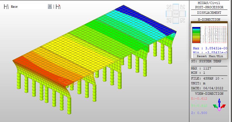
Indensesand,mediumdensesand,stiffclay,andsoftclay,thefindingsobtainedfromfiniteelementanalysisfor thecalculationofvertical displacement(i.e.in z direction)offrictionpile(group pile)model arearound4.83m, 4.73mm,4.5mm,and6.31mm,respectively.
Thetotalpermittedsettlementofapilefoundationis12.0mm,accordingtotheIndiancodeofpractise(IS:2911, Part4,1985),unlessafigureotherthan12.0mmisindicateddependentonthenatureandtypeofconstruction.
International Research Journal of Engineering and Technology (IRJET) e ISSN:2395 0056
Volume: 09 Issue: 06 | June 2022 www.irjet.net p ISSN:2395 0072
AccordingtoIScode,verticaldisplacementindensesandandmediumdensesandisfoundtobewithinacceptable limits.
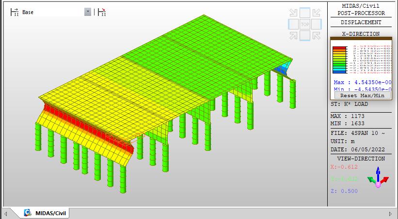
Table 3 depicts the vertical displacement of pile foundation of integral bridge in stiff clay, which is found to be roughlythesameastheallowablelimit.
TypeofSoil Vertical Displacement of pile foundation Vertical Displacement of DeckSlab
DenseSand 4.83mm 40.6mm MediumDenseSand 4.7243mm 42.3mm StiffClay 4.5435mm 51.0mm SoftClay 6.31mm 74.7mm
Vertical Displacement of Pile Foundation
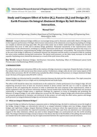
Dense Sand: Displacements due to Earth Pressure Load on Dense Sand
International Research Journal of Engineering and Technology (IRJET) e ISSN:2395 0056
Volume: 09 Issue: 06 | June 2022 www.irjet.net p ISSN:2395 0072
International Research Journal of Engineering and Technology (IRJET) e ISSN:2395 0056
Volume: 09 Issue: 06 | June 2022 www.irjet.net p ISSN:2395 0072
According to the findings, the vertical displacement in dense sand and soft clay is estimated to be 4.83 mm and 6.31mm,respectively.
AccordingtoIS:2911,Part4,1985,themaximumalloweddeformationofagrouppileis12.0mm.
In dense and medium sand, vertical pile displacement is within legal limits, while in soft soil, vertical pile foundationdisplacementexceedspermissiblelimits.
The vertical displacement of the deck slab of an integral bridge supported by abutment and friction pile foundationiscalculatedtobe40.6mm,42.3mm51.0mm,and74.7mmindensesand,mediumdensesand,stiff clay,andsoftclay,respectively
AccordingtoIS800:2007(2007),themaximumpermitteddeformationofthedeckslabforfourspansataspanof tenmetresinanintegratedbridgeis67.0mm.
The results showed that the vertical displacement of the deck slab of the bridge model is within limits in dense sand,mediumsand,andstiffclay,butthattheverticaldisplacementofthedeckslabinsoftclayis74.7mm,which is greater than the permissible limit of IS code (IS: 2911, Part 4, 1985), indicating that soft clay is not safe for design
International Research Journal of Engineering and Technology (IRJET) e ISSN:2395 0056
IRC.SP 115:2018,GuidelinesforDesignofIntegralBridges.
PD6694 1 Eurocode,:Recommendationsforthedesignofstructuressubjecttotrafficloadingtoen1997
Soil structureinteractioninintegralabutmentbridgesCatarinaFartaria
Seminar on Soil structure interaction By MIDAS Academy UK Pere Alfaras Calvo Principal Bridge Engineer ARCADIS.
IS800:2007IndianstandardcodeofpracticeforGeneralConstructioninSteel,BureauofIndianStandards,New Delhi
IS2911:1987.IndianstandardcodeofpracticeforGeneralConstructionand DesignofPilefoundation,Bureauof IndianStandards,NewDelhi.
IRC6:2000.IndianstandardcodeofpracticeforGeneralConstructioninRoadBridge,BureauofIndianStandards, NewDelhi.
IS 456:2000 Indian standard code of practice for General Construction in Concrete, Bureau of Indian Standards, NewDelhi.
Terzaghi,K.andPeck,R.B.(1967).SoilMechanicsinEngineeringPractice,NewYork,JohnWileyandSonsInc.
MIDASCIVIL(ver.1.1).Finiteelementbasedcommercialsoftwarefordesign.
Volume: 09 Issue: 06 | June 2022 www.irjet.net p ISSN:2395 0072 © 2022, IRJET | Impact Factor value: 7.529 | ISO 9001:2008 Certified Journal
Kim, W. and Laman, J.A. (2009). Load and Resistance Factor Design for Integral Abutment Bridges. PhD. Dissertation.ThePennsylvaniaStateUniversity,PA,USA.