International Research Journal of Engineering and Technology (IRJET) e ISSN:2395 0056

Volume: 09 Issue: 06 | June 2022 www.irjet.net p ISSN:2395 0072
ABSTRACT:
It is not easy to design a huge building by manually it takes time and manpower too, but by using software it saves time and manpower. The commercial cum residential building has mixed stories, with the ground floor consisting of commercial shops and the first floor consisting of residential floor of 2BHK flat. In big cities, very limited land is available and it is of high cost. The primary goal of our project is to gain sufficient knowledge in planning, design, modeling, and analysis of a commercial cum residential building. In this project, planning and drafting are done by using Autodesk AutoCAD, 3D Modeling is done by using Autodesk Revit Architecture, and Analysis and Design are done by using StaadPRO.V8i. Manual calculations of structural members like Slab, Beam, Column, and footing are done by the Limit State Method by using IS456:2000, IS875 and design aid SP16 code.
KEYWORDS- Autodesk AutoCAD, Autodesk Revit Architecture, StaadPRO.V8i, Planning, Design, Modeling, analysis.
1. INTRODUCTION:
Our project is “Design and modeling of commercial and Residential Building by using Autodesk Revit Architecture andStaadPRO.”Themainobjectiveofourprojectistogain sufficient Knowledge in planning, Design, Modeling and Analysis of a commercial cum residential building. It is a reinforcedconcreteframedstructureconsistingofG+1.All the structural members are designed by using National Building Code. IS 456:2000, IS 875, and design aid SP16. The structural components like Slab, Beam, Column and footing are manually designed by using Limit State Method.
Materials were used as specified by the National Building Code. For all the design, Concrete M20 grade and Fe 500 steelbars.BrickwallsareinC.M1:5mixwithwallexternal and internal wall thickness of 230 mm and 150 mm
respectively.Thetotalareaofourbuildingis139sq.m.The commercial shops had a glass wall for shops. Commercial space includes three shops, Two Store rooms, One Staffroom and two separate toilets for male as well as female and a staircase of 3 m wide. First floor is a residentialfloor(2BHK)withallthefacilities.
LITERATURE REVIEW-
1. V. S. Nagasai et al. (2019), “Planning, Analysis and DesignofResidentialBuilding(G+5)ByusingSTAAD Pro.” This paper deals with Frame analysis, which was done by STAAD.pro. Slab and beams were designed as per IS code 456 2000. The properties such as shear, deflection, development, torsions are definedbytheIScodeprovisions.
2. Falak Vats (2019), “Review paper on design and analysis of multi storey building by the use of Stadd.Pro,” He concluded that Stadd.Pro provides a much faster approach to structural analysis and designwithachancesofminimumerrors.Therehas been several research conducted comparing the results from Stadd.Pro to the manually calculated results, which all support the use of Stadd.Pro over manual the one. Stadd.Pro is a much better way to analyse complicated load combinations and is quite versatile.
3. Sowrav Saha, et al. (2021), “DesignandAnalysisof Multistorey (G+14) Residential Building Using Staad.Pro&Autocad”Theaimoftheirprojectwasto bringanideatoplan,throughanalysisanddesignof a multi storeyed, earthquake resistant residential building.They wereunsuccessfulinfullycompleting the project in a successful and efficient manner by consideringalltherelevantfeaturesgiven.
4. R. S. Bute, et al. (2018), – “Design a detailed 3D model of a building With the comparison of manual and Software estimates on Autodesk revit”, they
“Design and modeling of commercial cum residential building by using Autodesk Revit and StaadPRO.”Namrata S. Patil1, Vaishinavi N. Ghodake2, Rucha N Arali3, Yogesh U Kulkarni4 1,2,3B Tech Student Dept. of Civil Engineering DBATU University, Maharashtra, India 4Assistant Professor, Dept. of Civil Engineering, DBTU University, Maharashtra, India ***
International Research Journal of Engineering and Technology (IRJET) e ISSN:2395 0056


Volume: 09 Issue: 06 | June 2022 www.irjet.net p ISSN:2395 0072
concluded for the uses of scheduling and cost estimating in Autodesk Revit respectively, and provided a case study to show how Autodesk Revit can work for Architects, Engineers and contractors. As well as comparing Autodesk Revit Estimate with ManualEstimate.
5. Amar Hugar et al. (2016), has been discussed that the Computer Aided Design of Residential Building involves scrutiny of building using STAAD.Pro and a physical design of the structure. Traditional method of study show tedious calculations, and such tests are time consuming task. Analysis is made quickly byusingsoftware.Thisprojectcompletelydealswith scrutiny of the building using the software STAAD.Pro. Finally, the results are compared with physical calculations. The elements are created as perIS:456 2000.
6. Bandipati Anup et al. (2016), thispaperdealswith evaluating and planing a multi storeyed building [G + 2 (3 dimensional frame)] adopting STAAD Pro. The technique used in STAAD.Pro is limit state technique.Initiallytheyhavecreated2 Dframesand cross checked with manual calculations.They tested and created a G + 2 storey building [2 D Frame] instantlyforallfeasibleloadcombinations.Thework has been finished with some more multi storyed 2 Dimensional and 3 Dimensional frames beneath variousloadcombinations.
4. METHODOLOGY
PLANNING
MANUAL ANALYSIS COMPARION OF RESULTS
CONCLUSION


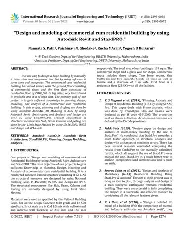
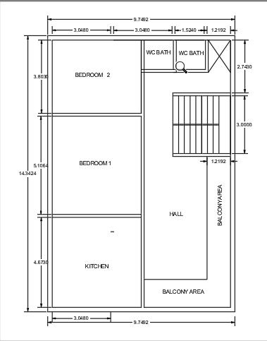
4.1 DESIGN USING AUTOCAD
AutoCAD is a computer aided design and drafting software application. AutoCAD is used to draft out plans, elevations, cross sections etc. of a building. The CAD drawing helps to identify the details such as balcony, kitchen, rooms, dining hall, thickness of wall, sitedetailsetc.
AUTOCAD PLAN GroundFloorPlan
International Research Journal of Engineering and Technology (IRJET) e ISSN:2395 0056
Volume: 09 Issue: 06 | June 2022 www.irjet.net p ISSN:2395 0072
FirstFloorPlan
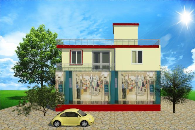
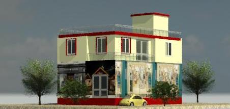
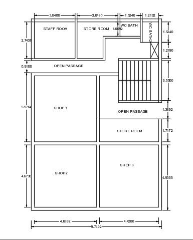
4.2 AUTODESK REVIT ARCHITECTURE 3D MODELING:
Nowadays,itisnecessarytocompleteaprojectwithin areasonabletimeandeconomically.AutodeskRevitis building information modeling softwares i.e., BIM software for architects, landscape architects, structural engineers, designers, and contractors. Autodesk Revit allows us to design and document a building by creating a three dimensional model that includesdesignandconstructioninformation,whichis also known as building information modeling After creating the model we used Revit rendering tool to makethemodelmorerealistic
International Research Journal of Engineering and Technology (IRJET) e ISSN:2395 0056
Volume: 09 Issue: 06 | June 2022 www.irjet.net p ISSN:2395 0072
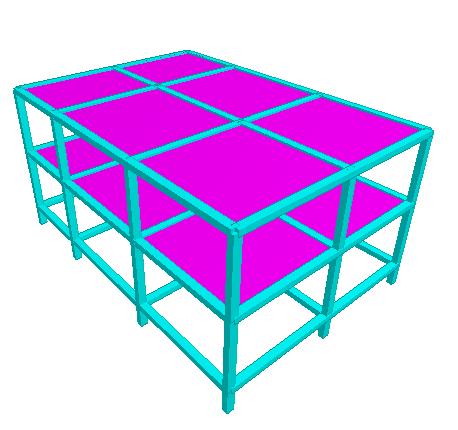
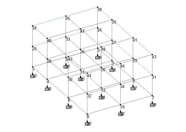
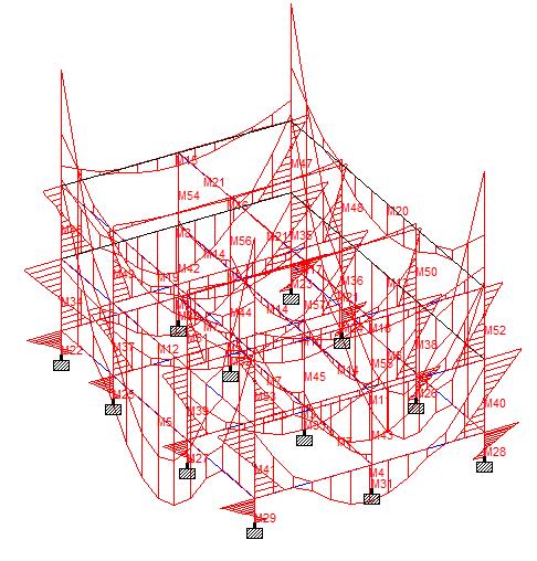
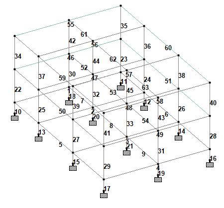
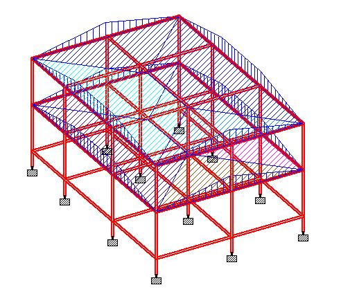
4.3 STAAD ANALYSIS AND MODELING
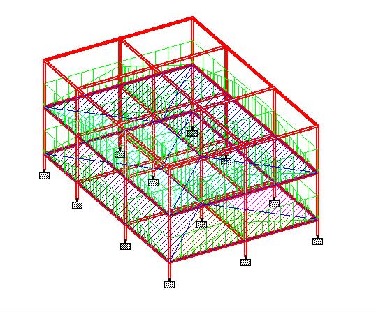
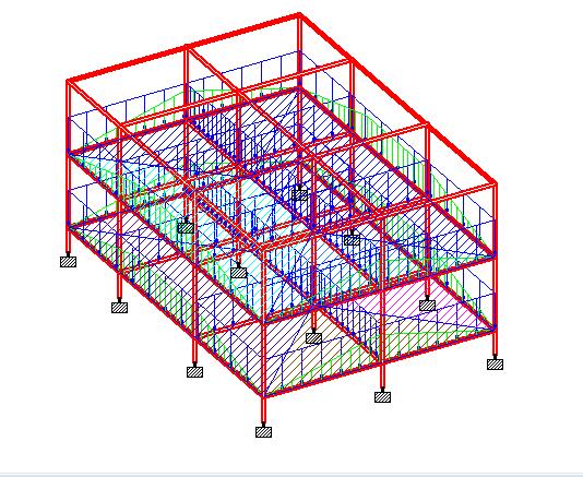
STAADPROisoneofthemostpopularsoftwarethatis used for analysis and designing towers, bridges, buildings etc.The first step in our process will be reading the plan that has been created. From this readingprocess,wewillgetalltheinformationsuchas the number of storeys, number of bays, loadings, etc. The G+1 building is modelled using the Structure WizardinsideSTAADProaccordingtothebuilding.
Member Section Dimensions (mm)
Beam 230x300
Column 230x300
SlabThickness 100
WallThickness External 230 Internal 150
Density of materials used: MATERIAL DENSITY
Plainconcrete 24.0KN/m Reinforced 25.0KN/m
Flooringmaterial (cm)
4.3.1 DEAD LOAD
20.0KN/m
Dead loads are the structural loads that include the self weight of the structural members such as walls, ceilings,floors,plasteretc.AccordingtoIS875part2,
Deadload 15KN/M
Self weight is the body’s own weight of body, due to the mass present in it. In STAAD Pro, we can directly add the self weight by selecting the whole structure and simply specifying the direction of force. It is a dead load. AccordingtoIS875part2,
Selfweight Factor= 1KN/M
4.3.2 LIVE LOAD
Live loads are temporary loads that are applied to the structure on and off over the life of the structure. AccordingtoIS875part2,
International Research Journal of Engineering and Technology (IRJET) e ISSN:2395 0056
Volume: 09 Issue: 06 | June 2022 www.irjet.net p ISSN:2395 0072
International Research Journal of Engineering and Technology (IRJET) e ISSN:2395 0056
Volume: 09 Issue: 06 | June 2022 www.irjet.net p ISSN:2395 0072
5. SAMPLE MANUAL CALCULATION
5.1 Design of Beam
Beams shall normally be provided under the wall or under a heavy concentrated load. Beams transfer load fromslabstocolumns,beamsaredesignedforbending.In general, we have two types of beam: single and double. Similar to columns, the geometry and perimeters of the beamsareassigned.
Therearethreetypesofreinforcedconcretebeams
1.Singlereinforcedbeams
2.Doublereinforcedconcrete
3.Flangedbeams
Step 1
Dimensions
AB=4.83m BC=4.60m
BeamSize=230mm*300mm
Cover=50mm EffectiveDepth=250mm
ForM20concreteandFe500steel Step 2
Load Calculation
ForspanAB
TrapazoidalArea=½*(0.03+4.83)*2.415=5.86m2
i. Selfweight=0.23*0.30*1*25=1.725KN/m
ii. WallLoad=0.23*1*19=4.37KN/m
iii. SlabLoad=12*5.86/4.83=14.55KN/m
TotalWorkingload=20.645KN/m
FactoredLoad=30.96KN/m
ForSpamBC
International Research Journal of Engineering and Technology (IRJET) e ISSN:2395 0056
Volume: 09 Issue: 06 | June 2022 www.irjet.net p ISSN:2395 0072
Trapezoidalarea=½*(0.25+4.61)*2.30=5.59m2
i. Selfweight=1.725KN/m
ii. Wallload=4.37KN/m
iii. SlabLoad=13.64KN/m
Totalworkingload=19.74KN/m
Factoredload=29.60KN/m
Step 3
Calculation of FEMs
SpanAB
MAB= wl2/12= 30.96*4.832/12= 60.18KN
MBA=60.18KN SpanBC MBC= wl2/12= 29.60*4.612/12= 52.42KN MCB=52.42KN
Step 4
Calculation
Step 5 Moment Distribution Table
RA=76.76+1.15=88.27KN
RB=74.76+68.22 1.15+1.31=143.14KN
RC=68.22 1.31=66.91KN
S.F. Calculation
SFAL=0
SFAR=88.27KN
SFBL=88.27 (30.96*4.83)= 61.26KN
SFBR= 61.26+143.14=81.88KN
SFCL=81.88 (29.60*4.61)= 66.91KN
SFCR=0
Calculation of Mulim
=0.133Fckbd2 =0.133*20*230*2502 =38.24KN
SpanAB=Wl2/8=.96*4.832/8=90.28KN.m
SpanBC=Wl2/8=29.60*4.612/8=78.63KN.M
Calculation of Ast Span AB
Ast=0.5*20/500*[1 4.6*59.25*106/20*230*2502] *230*250 =887.75mm2
No.ofBars=887.75/ /4*162 =4.41 6Nos. Asc=0.5*20/500*[1 4.6*31.03*106/20*230*2502] *230*250 =333.96mm2
No.ofBars=333.96/ /4*122 =2.95 4Nos.
Span BC
Ast=0.5*20/500*[1 4.6*53.43*106/20*230*2502] *230*250 =711.91mm2
No.ofBars=711.91/ /4*162 =3.50 4Nos. Asc=0.5*20/500*[1 4.6*25.2*106/20*230*2502] *230*250 =261.59mm2
International Research Journal of Engineering and Technology (IRJET) e ISSN:2395 0056
Volume: 09 Issue: 06 | June 2022 www.irjet.net p ISSN:2395 0072
No.ofBars=261.57/ /4*122 =2.30 4Nos.
Check for shear
For span AB
Vu=Wl/2=74.76 c =74.76*103/230*250=1.30 Pt=887.75/230*250*100=1.54
Pt 1.50 0.72 1.54 X 1.75 0.75
X=0.75 (0.75 0.72)/(1.75 1.50)*(1.54 1.50) X=0.74 v> c
Assume8mm2leggedverticalstirrups.
Vs=Vu c*b*d=74.76*106 0.74*230*250 Vs=32.21KN
Spacing=0.87*500*100.53*250/32.21*103 =339.41mm
Sv=0.75d=0.75*250=187.5mm Sv=300mm
Provide190mmSpacing.
Check for shear Span BC
Vu=Wl/2=68.22 v=68.22*103/230*250=1.18 Pt=711.91/230*250*100=1.23
Pt
1.00 0.62 1.23 X 1.25 0.67
X=0.67 (0.67 0.62)/(1.25 1.00)*(1.23*1.00) c=0.62
v> c
Hence,shearreinforcementrequired.
Provide8mm 2leggedverticalstirrups
Vs=Vu c*b*d=68.22*103 0.62*230*250=32.57KN
Spacing=0.87*500*100.53*250/32.57*103 =335.67mm
Sv=0.75d=0.75*250=187.5mm Sv=300mm
Provide 8 mm 2 legged vertical stirrups @190 mm Spacing.
6. CONCLUSION
The primary goal of the project has been met, which is to gain knowledge in design, modeling, draftingandanalysisusingsoftware’s.
Getting familiar with structural software like AutoCAD, Autodesk Revit Architecture and staadPro.
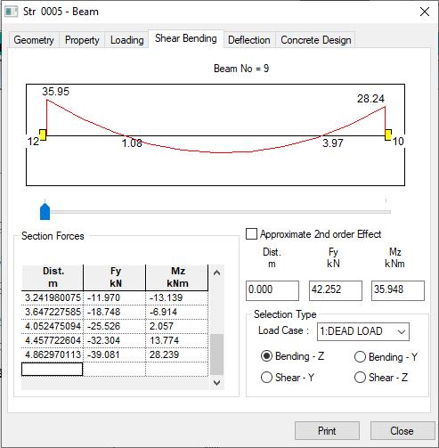
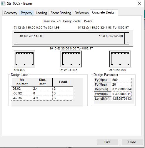
StaadPro frame analysis of a building is done by StaadProasperIS456 2000,IS875andDesignAid SP 16. The shear and deflection are within the Is 456:2000.
Software analysis was compared with manual analysis,andtheresultswerealmostthe same.
Aftercomparisonofthesampledataforbeam,the Astrequirementisthesameinmanualanalysisas wellassoftwareanalysis.
The modeling of the building in Autodesk Revit software gives a beautiful, realistic view of the building.
7. REFERENCES
1. Pranav Bhagwat, Rahul Shinde “Autodesk Revit: Implementation in practice”, October December 2003.
© 2022, IRJET | Impact Factor value: 7.529 | ISO 9001:2008 Certified Journal | Page1281
International Research Journal of Engineering and Technology (IRJET) e ISSN:2395 0056
2. Analysis of Multistoried Building considering Hybrid Structure Tanha B. Shah, International Journal of innovative research volume1 issue 2. (PP. 81 180)(May2005)
3. Sergey P. Zotkina, “The Organization Of Autodesk Revit Software Interactions with Applications for Structuralaqnalysis”In2016.
4. Linomaia, “BIM Methodology, a new approach case studyofstructuralelementscreation”In2015.
5. RakeshReddy“Design&modelingofG+5commercial buildingbyAutodeskRevitArchitecture”In2019.
6. MenglinWang,“BuildingInformationModeling(BIM) Sitebuildinginterperabilitymethod”In2011.
7. R. S. Bute, “Design & Detail of 3D model of building with comparision of Manual & Software estimate on AutodeskRevit”In2018.
8. Xinan Jiang, “Development in cost estimating & schedulinginAutodeskRevit”In2008.
9. Sreehna KS, “Structural Analysis & design of B+G+4 storiedapartmentbuilding”In2016.
10. Bandipati Anup, “Evaluate & Plan a Muiti Storeyed buildingadoptingSTAADPro”In2016.
11. Amar Hugar, “The CADD Design of Residential building involves scruting of Building using STAAD Pro&Physicaldesignofastructure”In2016.
12. Sourav Saha, “Design & Analysis of multi storey (G+4) Residential building using STAAD Pro & Auto CADD”In2021.
13. Falak Vats, “Review paper on design & analysis of Multi storey building bt the use of STAAD Pro” In 2019.
14. V. S. Nagasai, “Planning Analysis and Design of Residential Building (G+5) by using STAAD Pro” In 2019.
15. DhanavathSeva,In2017.
16. R. D. Deshpande, “Analysis Design & estimation of residential building”.
Volume: 09 Issue: 06 | June 2022 www.irjet.net p ISSN:2395 0072 © 2022, IRJET | Impact Factor value: 7.529 | ISO 9001:2008 Certified Journal | Page1282