International Research Journal of Engineering and Technology (IRJET) e ISSN:2395 0056

Volume: 09 Issue: 06 | June 2022 www.irjet.net p ISSN:2395 0072
IoT Based smart Battery Management System
Dinesh Panicker1 , Darsh Kapoor2 , Prajwal S.P3 , Mahesh A. Kamthe4
1Student, Dept of Electronics and Communication Engineering, MIT ADT University,Pune
2 Student Dept of Electronics and Communication Engineering, MIT ADT University
3Student Dept of Electronics and Communication Engineering, MIT ADT University 4Assistant Professor, Dept of Electronics and Communication Engineering, , MIT ADT University ***
Abstract – In this project, a model battery management system was developed and tested for a 1s an 3s battery pack.The parameters were sent to the cloud and data analysis was performed to find out the faulty cell in the battery pack. Passive cell balancing was performed, and the results were evaluatedfor a Lithium ion NMC Battery Pack of 3 cells. The cells are charged with CC CV charger for 1s and 3s respectively. This is all modelled for an e bike application, but the scope will be limited to a 3s battery pack
Key Words: BMS Battery Management System, IoT Internet of Things, NMC Nickel Manganese Cobalt Oxide, API ApplicationProgrammingInterface
1. INTRODUCTION
In this project, we'll measure voltage, current, and temperature and therefore the necessary balancing circuits and protection. Then, using an Arduino Nano, we'll create A battery management system for an E bike application. the informationobtainedaregoingtobetransferredtoacloudserverwiththeassistanceofaBOLTIoTmodule,andwe'lluse dataanalysistoworkoutwhichcellwithinthebatterypackisbad.Thebatterymanagementsystem'sbalancing function is additionally a very important feature. A correctbalance of the electrical battery management system will allow the batterycellstobeusedmoreefficientlyandsafelyforextendedperiodsofyourtime.
WewillalsodisplaytheresultsontheArduinoserialmonitorbeforeuploadingthemtothecloudserverviaan API.Over theUARTline,thesystemcommunicated withan BOLT module and transmitted data (voltage, temperature,current, SoC, and operating status) to a far off server. Simultaneously, a command infrastructure has been developed that may stop charginganddischargingfromtheremoteserverwhennecessary.ThisfunctionalsoaddsanIoTcapabilitytothesystem. the info that the battery management system sends to the remote server provides information about the system's supply and allows the balancing function to be evaluated. This IoT feature also allows you to regulate load output and considerthechargingprocess.
2. BLOCK DIAGRAM
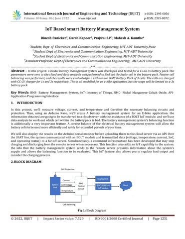
Fig 1: BlockDiagram
International Research Journal of Engineering and Technology (IRJET) e ISSN:2395 0056
Volume: 09 Issue: 06 | June 2022 www.irjet.net p ISSN:2395 0072
Thefigureabovedepictstheoverallblockdiagramofour project.TheArduinoNanomicrocontrollerfirstmeasures the voltage,current,andtemperatureofeachcell.TheparametersarethentransmittedtoaBOLT/ESP8266IoTboard,which transmits them to the cloud server. The battery pack has been subjected to some analysis using the NMC Cell Chemistry's OCV SOC look up table. The faulty cell is then detected, and the user is notified. The cloud analytics uses the OCV SOC datasettoidentifythefaultycellandalertstheuser.
3. CIRCUIT DIAGRAM
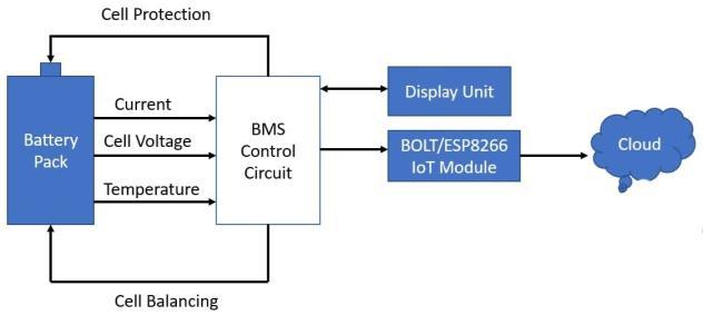
Fig 2: CircuitDiagram
InourProjectwehavetakenabatterypackof3cellsof3.5~3.6veach.
For voltage & current detection of the battery pack, we have connected an ACS712 hall effect sensor &then it is connectedtothemicrocontroller.Forvoltagedetectionformulausedis:
Voltage = Input vtg / 1023 * reference voltage (Vref) Here Vref is 0.000447V (or 4.47mV) since the VCCof the arduino is 4.68V
&forcurrentdetection,theformulausedis:
Current = (o/p Voltage offset voltage)/sensitivity
Heresensitivityrangesfrom66mV/Ato185mv/A.Theoffsetvoltageis490mV
For temperature sensing, we had used a thermistor. Input is given to the analog pin A8, the microcontroller convertsit to the digitaloutput using a suitable equation and it displaysiton the LCD(simulation). In hardware, we’redisplayingitontheBOLTIoTcloud
Fordisplayingvaluesarehadused16x2alphanumericLCD(simulation).
Coming to the battery protection part, we had used a relay for switching & grounding the circuit. We had programmeditinsuchawaythatwhenthe Temperatureofthebatterypackislessthan10deg orgreaterthan60 deg,thentherelaygroundsthecircuit.
TheactualhardwareforprotectionconsistsoftheDW01AICandsome06N03LAPowerMOSFETs whichare both includedinthe3sbattery balancing
+protectionboardandintheTP4056IC(for1sconfiguration)
International Research Journal of Engineering and Technology (IRJET) e ISSN:2395 0056
Volume: 09 Issue: 06 | June 2022 www.irjet.net p ISSN:2395 0072
4. LITERATURE SURVEY
Wehavereferredtothefollowingresearchpapersforourproject.Thefirstpaperisthemainonewhich gaveusageneral ideaoftheBMSdevelopment.
Table -1: LiteratureSurvey
Sr No PublicationsandAuthor
1 Yow Chyi Liu1 and Shyue BinChang2,“Design and Implementation of aSmartLithium IonBattery Capacity Estimation System for E Bike” in World ElectricVehicleJournalVol.4
2 Namith T, Preetham Shankpal, “Design and Development of EfficientBattery Charging and Cell BalancingforBattery
Management System” in SasTech Journal Volume 11, Issue 2, Sept 2012
3 lker Aydn, Özgür Üstün “A Basic Battery Management System Design with IoT Feature for LiFePO4 Batteries” in IEEE International Conference on Electricaland Electronics Engineering(ELECO)
4 Nathan Scharich, Brandon Schniter, Anthony Herbert, and Md. Shafiul Islam, “Battery Management System UsingArduino”in 2017 IEEE Technology &Engineering Management Conference(TEMSCON)
5 Balakumar Balasingam 1,* , Mostafa Ahmed 1 and Krishna Pattipati 2,“Battery Management Systems Challenges and Some Solutions” in Energies 2020
5. SYSTEM SPECFICATIONS
Hardware Specifications:
1. ArduinoNanoBoard
TitleTaken
BatteryManagementwith Lithium Ioncellsfor an E bikeapplication
CircuitDesignfortheBMS
ImplementationofIoTin BMS
ArduinoImplementation ofBMS
BMS faults andsafety
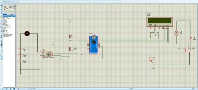
IndirectsensingisusedbytheACS712currentsensor.When currentflowsacrossthewire,directsensingusesOhm'slaw to calculatethefreefallacrossit.Inindirectsensing,themagneticfluxiscalculatedusingFaraday'slawortheAmperelaw.
This IC detects this using a low offset Hall sensor. This sensor is located on the IC's surface along a copper conduction path. It's a copper strip that connects the sensor's IP+ and IP pins internally. When current flows through this copper conductor, it generates a magnetic flux, which the Hall Effect sensor detects. The hall effect sensor produces voltage proportionaltothesensedforcefield,whichisusedtogeneratelivecurrent.
International Research Journal of Engineering and Technology (IRJET) e ISSN:2395 0056
Volume: 09 Issue: 06 | June 2022 www.irjet.net p ISSN:2395 0072
6.2 BOLT IoT features and Working:
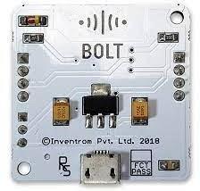
Fig 4: BOLTIoTcontents
TheBOLTIoTdevelopmentboardincludestheESP 12Emodule,whichcontainsachipwithaTensilicaXtensa32 bitLX106 RISC microprocessor. This microprocessor supports RTOS and operates at an adjustable clock frequency of80MHz to 160MHz. To store data and programmes, the BOLT IoT has 128 KB of RAM and 4MB of nonvolatile storage. Itshigh processing power, combined with built in Wi Fi/Bluetooth and Deep Sleep Operating features, makes it ideal for IoT projects.Theprimaryfunctionofthisdeviceistosenddatatothecloudandperformdataanalysisonthe cloud.
TheBOLTIoTwillbepoweredbyaMicroUSBjackandaVINpin(ExternalSupplyPin).IthasinterfacesforUART,SPI,andI2C.
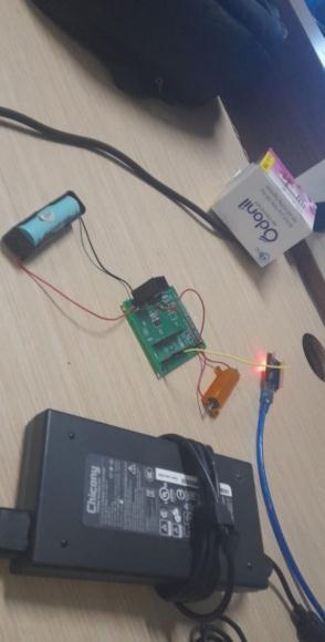
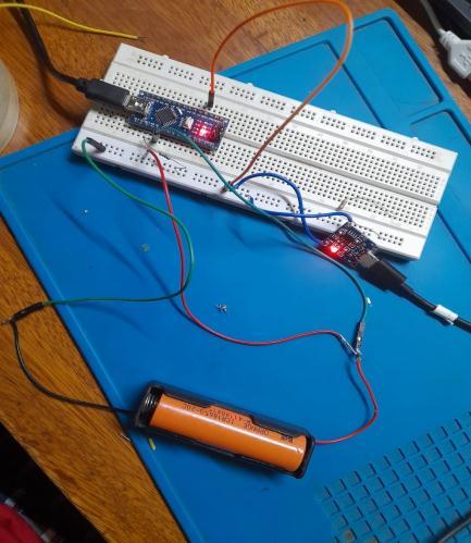
6.3 Actual Circuit Connections
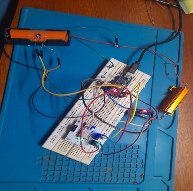
Fig 5: Hardwareconnections
Thecircuitconnectionforthe1sbatteryisshownabove.Thevoltageofthebatteryismeasureddirectlythroughthewire.The current is measured using an ACS712 current sensor. The temperature of the system is measured using an NTC Thermistor.Theseparametersarethensenttothecloudforanalysis.Thefaultycellisdetectedandtheuserisnotified.This experimentuseda2ohm,10Wshuntthatcandischargethecellinlessthan30minutes.
International Research Journal of Engineering and Technology (IRJET) e ISSN:2395 0056
Volume: 09 Issue: 06 | June 2022 www.irjet.net p ISSN:2395 0072
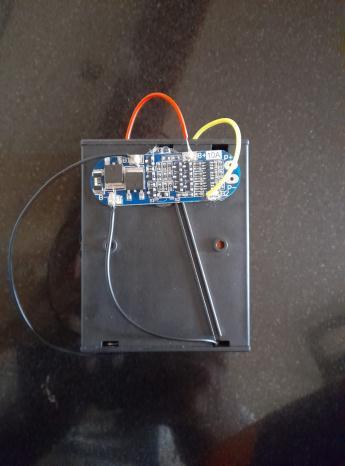
6.4 3S Battery Protection and Balancing Board 10AWorking:
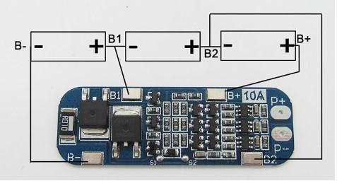
Fig 6: BatteryProtectionandBalancingBoardconnections
• Theconnectionsarestrictlyinaccordancewiththewiringdiagram
• Itwillhaveoutputonce wehavechargedtheprimaryline.
• Thiscircuitincludesthe06N03LAPowerMOSFET,whichisusedforpassivecellbalancing.
• ItalsoincludestheDW01CICModule,whichprovidesovervoltage/overcurrentprotection.
6.5 DC-DC Buck Converter 4.5-50V to 3-40VAdjustable Step Down Power Module:
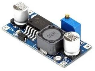
The LM2596HVS module is a high input voltage variant of the LM2596 Module. The LM2596HV module is a buck converter module with an input voltage range of 4.5 to 50 volts and an output voltage range of three to 40 volts. This variable output can be adjusted using the on board multi turn potentiometer. This will help charging our 3s battery pack.
Fig 7: LM2596HVSBuckconvertermodule
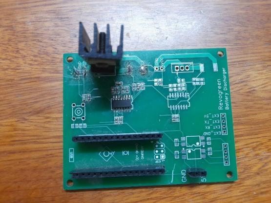
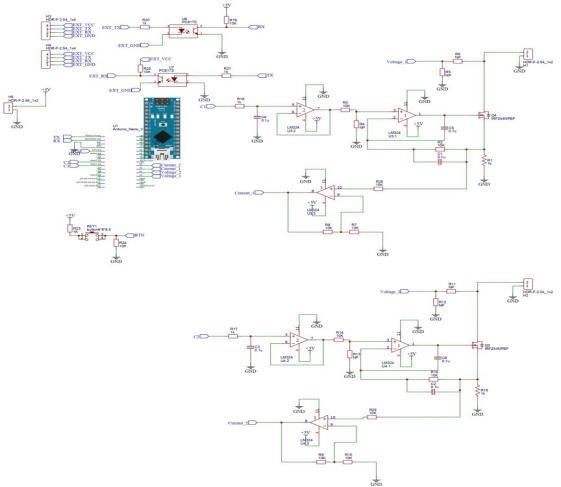
6.6 Discharger board Schematics and PCB
The Discharger board is designed for the 1s battery configuration. We have used IRF544 MOSFET to dissipate the heat and balance the voltage properly. A Shunt output is connected to the board along with a 18650 battery. We also have an operational amplifier to measure the current discharged in the circuit. This arrangement uses a direct current measurement method with a sense resistor and external amplifier (opamp in this case) to determine the current. We alsohavereservedspacesforsomeoptocouplersifwewanttousehighercurrents.
International Research Journal of Engineering and Technology (IRJET) e ISSN:2395 0056
Volume: 09 Issue: 06 | June 2022 www.irjet.net p ISSN:2395 0072
International Research Journal of Engineering
and
Technology (IRJET) e ISSN:2395 0056
Volume: 09 Issue: 06 | June 2022 www.irjet.net p ISSN:2395 0072
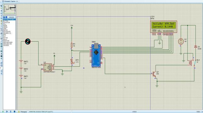
The circuit was simulated in proteus along with anACS712current sensor and a 10k NTC thermistor. The voltage was measured directly bythe A0pinoftheArduino Nano Microcontroller, currentbytheA1pinandtemperaturebytheA2 pin.Insimulationonlywe’veincludedarelaycircuitforprotection,whichwouldnotbenecessaryinthepracticalhardware.

International Research Journal of Engineering and Technology (IRJET) e ISSN:2395 0056
Volume: 09 Issue: 06 | June 2022 www.irjet.net p ISSN:2395 0072
Fig 13: ChargingHardwarecircuit
In the charging hardware, we’ve implemented it using a TP4056 IC and charged this single cell battery. There are provisionsforvoltage/currentspikesasitcontainstheDW01AIC.
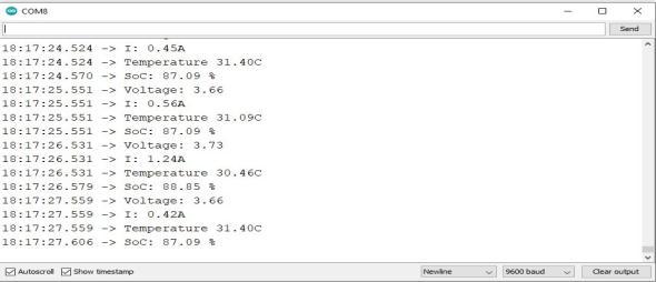
Fig 14: Resultsdisplayedontheserialmonitoraresenttothecloud
Fig 15:3scellbalancing+protection
International Research Journal of Engineering and Technology (IRJET) e ISSN:2395 0056
Volume: 09 Issue: 06 | June 2022 www.irjet.net p ISSN:2395 0072
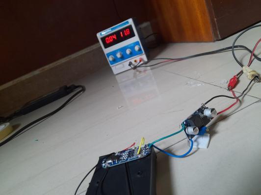
The 3s cell battery pack is protected by the charger protection board, which offers both cell balancing and protection. ThecellsarechargedbyaLM2596HVSbuck convertermodule.Thisarrangementensuresallthecellsare equallycharged andtherearenovoltage/currentspikes.
Fig 16: 3scellcharging
8. CONCLUSION
Thedevelopedsystemisusedfor a3saswellasfor a1s batterypacksystem.Thevoltage,current,temperatureandSoC values weresentto thecloud. In our system, we have implemented IoT and data analytics through cloud, which helped usstudyandobserveeachparameterandbehaviorof eachbatteryindetail. Using thisdata,wecandeducehow each cell inthebatterypackisperforming, not asacollective, butindividually, which willhelpisolate anyproblem causing cells. Faultcodeshavealsobeenimplementedwhichwillbedisplayedonthecloudsothat eventheendusercanunderstandin shortwhatmightbetheproblem.Wecanevenpreventmanyaccidentalfiresduetotemperatureorexternalstimuluswith the help of our system. The charging and discharging of both 3s and 1s cells have been shown and thus we have built a batterypackoftherequiredconfiguration.
ACKNOWLEDGEMENT
Thesatisfactionthataccompaniesthesuccessfulcompletionofthetaskwouldbeputincompletewithoutthementionofthe peoplewhomadeitpossible,whoseconstantguidanceandencouragementcrownalltheeffortswithsuccess.
It is my greatest pleasure to thank Prof. Dr. Virendra V. Shete (Vice Principal, MIT SOE and Head, Department of Electronics and Communication, MIT ADT University) forprovidingusheartfullencouragementsupportandallowing us toworkinsucharesourcefullabofthisesteemedinstituteandtherebyfulfillingoneofmydreams.
I whole heartedly thank my project guide Prof. Mahesh A. Kamthe for his consistent guidance, expert academic and supportthroughouttheproject,withouthisgreatconcepts&inspirationitwouldhavebeenimpossible.
Ithankmyparentsfortheiremotionalandfinancialsupportwhichtheyprovidedduringthisproject.
We show gratitude to our Honourable Principal Prof. Dr. Kishore Ravande, for having provided all the facilities and support.
Ithanktoallfacultieswhodirectlyandindirectlyhelpedusinthecompletionofthisproject.
International Research Journal of Engineering and Technology (IRJET) e ISSN:2395 0056
Volume: 09 Issue: 06 | June 2022 www.irjet.net p ISSN:2395 0072
REFERENCES
[1] Yow Chyi Liu and Shyue Bin Chang,“Design and Implementation of a Smart Lithium Ion Battery Capacity EstimationSystemforE Bike”inWorldElectricVehicleJournalVol.4
[2] NamithT,PreethamShankpal,“DesignandDevelopment ofEfficientBattery Charging and CellBalancing for Battery ManagementSystem”inSasTechJournalVolume11,Issue2,Sept2012
[3] lker Aydn, Özgür Üstün “A Basic Battery Management System Design with IoT Feature for LiFePO4 Batteries ” in IEEEInternationalConferenceonElectricalandElectronicsEngineering(ELECO)
[4] Nathan Scharich, Brandon Schniter, Anthony Herbert, and Md. Shafiul Islam, “Battery Management System Using Arduino”in2017IEEETechnology&EngineeringManagementConference(TEMSCON)
[5] Balakumar Balasingam, Mostafa Ahmed and Krishna Pattipati,“Battery Management Systems Challenges and somesolutions”inEnergies2020
[6] YANG Xu , SHEN Jiang and TONG XIN Zhang, “Researchand design of lithium battery management system for electricbicyclebasedonInternetofthingstechnology”in2019ChineseAutomationCongress(CAC)
[7] Goals for Advanced Batteries for EVs; United States Council for Automotive Research LLC: Southfield, MI, USA,2009; Available online:http://www.uscar.org/commands/files_download. php?files_id=27 (assessed on 1August2011).
[8] Stuart,T.;Fang,F.;Wang,X.P.;Ashtiani,C.;Pesaran,A.AmodularbatterymanagementsystemforHEVs.FutureCar Congress2002,doi:10.4271/2002 01 1918.
[9] Andrea, D. Battery Management Systems for Large LithiumIon Battery Packs, 1st ed.; Artech House: London, UK, 2010;pp.22 110.
[10] Meissner, E.; Richter, G. Battery monitoring and electrical energy management precondition forfuture vehicle electricpowersystems.J.PowerSources2003,116,79 98.
[11] Gold, S. A PSPICE Macromodel for Lithium Ion Batteries. In Proceedings of IEEE the Twelfth Annual Battery ConferenceonApplicationsandAdvances,LongBeach,CA,USA,14 17January1997;pp.215 222.
[12] DS2726 Datasheet Rev 3. MAXIM 5 Cell to 10 Cell Li+ Protector with Cell Balancing; Maxim Integrated Products, Inc.: Sunnyvale, CA, USA, 2010; Available online: http://datasheets.maxim iccom/en/ds/DS2726.pdf (accessed on 1 August2011).
[13] BQ78PL114 Datasheet. PowerLAN Gateway Battery Management Controller with PowerPump Cell Balancing; Texas Instruments Inc.: Dallas, TX, USA, 2009; Available online:http://www.ti.com/lit/ds/symlink/bq78pl114.pdf (accessedon1August2011).
[14] Vishal Sapre, “Essentials of a Battery Management System” in Tech Future section of the Electronics for You MagazineMay2022
[15] YinjiaoXing,EdenW.M. Ma,KwokL. Tsui andMichaelPecht, “Battery Management Systems in Electric and Hybrid Vehicles”inenergiesjournal2011
[16] Martin Bata and David Mike, “Battery Management Hardware Design for a Student Electric Racing Car” in ElsevierIFACConferencePaper
[17] Yiu, Nicholas. Jing, Linda. Yeh, Yen. He, Katherine. Zheng,Eric. “State of Batteries Report 2020.” BatteryBits, 16 January2021.Web.Dateaccessed.