International Research Journal of Engineering and Technology (IRJET) e ISSN:2395 0056

Volume: 09 Issue: 06 | June 2022 www.irjet.net p ISSN:2395 0072
International Research Journal of Engineering and Technology (IRJET) e ISSN:2395 0056
Volume: 09 Issue: 06 | June 2022 www.irjet.net p ISSN:2395 0072
4
123 Student, Department of Electronics and communication engineering, Mahendra engineering college, Namakkal, Tamil nadu, India.
4 Assistant Professor, Department of Electronics and communication engineering, Mahendra engineering college, Namakkal, Tamil nadu, India. ***
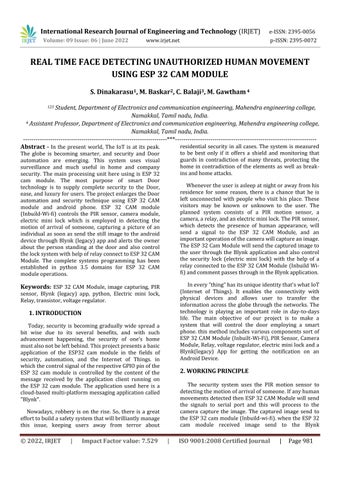
Abstract In the present world, The IoT is at its peak. The globe is becoming smarter, and security and Door automation are emerging. This system uses visual surveillance and much useful in home and company security. The main processing unit here using is ESP 32 cam module. The most purpose of smart Door technology is to supply complete security to the Door, ease,andluxuryforusers.TheprojectenlargestheDoor automation and security technique using ESP 32 CAM module and android phone. ESP 32 CAM module (Inbuild Wi fi) controls the PIR sensor, camera module, electric mini lock which is employed in detecting the motion of arrival of someone, capturing a picture of an individual as soon as send the still image to the android device through Blynk (legacy) app and alerts the owner about the person standing at the door and also control thelocksystemwithhelpofrelayconnecttoESP32CAM Module. The complete systems programming has been established in python 3.5 domains for ESP 32 CAM moduleoperations.
Keywords: ESP 32 CAM Module, image capturing, PIR sensor, Blynk (legacy) app, python, Electric mini lock, Relay,transistor,voltageregulator.
Today, security is becoming gradually wide spread a bit wise due to its several benefits, and with such advancement happening, the security of one’s home mustalsonotbeleftbehind.Thisprojectpresentsabasic application of the ESP32 cam module in the fields of security, automation, and the Internet of Things. in whichthecontrolsignaloftherespectiveGPIOpinofthe ESP 32 cam module is controlled by the content of the message received by the application client running on the ESP 32 cam module. The application used here is a cloud basedmulti platformmessagingapplicationcalled "Blynk".
Nowadays, robbery is on the rise. So, there is a great efforttobuildasafetysystemthatwillbrilliantlymanage this issue, keeping users away from terror about
residential security in all cases. The system is measured to be best only if it offers a shield and monitoring that guards in contradiction of many threats, protecting the home in contradiction of the elements as well as break insandhomeattacks.
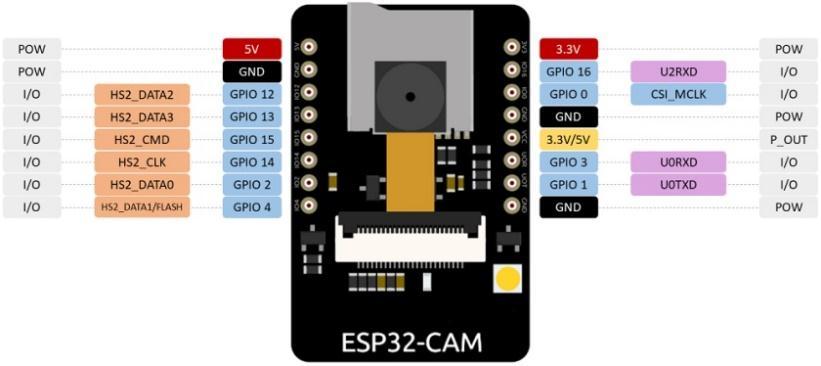
Whenevertheuserisasleepatnightorawayfromhis residence for some reason, there is a chance that he is left unconnected with people who visit his place. These visitors may be known or unknown to the user. The planned system consists of a PIR motion sensor, a camera,arelay,andanelectricminilock.ThePIRsensor, which detects the presence of human appearance, will send a signal to the ESP 32 CAM Module, and an importantoperationofthecamerawillcaptureanimage. TheESP32CamModulewillsendthecapturedimageto the user through the Blynk application and also control the security lock (electric mini lock) with the help of a relayconnected to theESP 32CAMModule (Inbuild Wi fi)andcommentpassesthroughintheBlynkapplication.
Inevery“thing”hasitsuniqueidentitythat'swhatIoT (Internet of Things). It enables the connectivity with physical devices and allows user to transfer the information across the globe through the networks. The technology is playing an important role in day to days life. The main objective of our project is to make a system that will control the door employing a smart phone.this methodincludes variouscomponentssort of ESP32CAMModule(Inbuilt Wi Fi),PIR Sensor,Camera Module,Relay,voltageregulator,electricminilockanda Blynk(legacy) App for getting the notification on an AndroidDevice
The security system uses the PIR motion sensor to detectingthemotionofarrivalofsomeone.Ifanyhuman movementsdetectedthenESP32CAMModulewillsend the signals to serial port and this will process to the camera capture the image. The captured image send to theESP32cammodule(Inbuild wi fi).whentheESP32 cam module received image send to the Blynk
International Research Journal of Engineering and Technology (IRJET) e ISSN:2395 0056
Volume: 09 Issue: 06 | June 2022 www.irjet.net p ISSN:2395 0072
applicationandalsocontroltheelectricminilocksystem itsconnectedto5pin12vrelayandthenrelayconnected totheESP32cammodule.
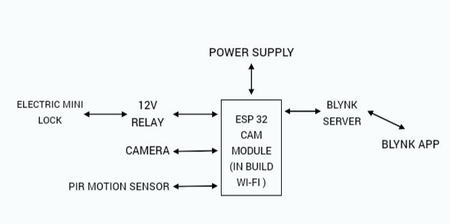
microSD card port. Another thing missing from the ESP32 CAM module could be a USB port. so as to program this device, you’ll must make use of an FTDI adapter.
Whenevertheuserisawayfromhisresidencefor some reason, there is a chance that he is left unconnected with people who visit his place. These visitors may be known or unknown to the user. For any unauthorized, the owner has to send command as open forenteringintotheresidence
The“top”oftheboardhastheconnectorforthe camera module, furthermore because the microSD (sometimes called “TF”) card socket. You’ll also note a squarewhiteLED onthehighestofthemodule,thiswill actasa“flash”forilluminatingthetopicyou'retryingto look at with the camera. The underside of the printed circuit has the ESP32 S module. It also contains a connector for an external antenna, in addition as an indoor antenna that's etched onto the card. I’ll explain thewaytousetheexternalantennashortly.Anotherkey component located underneath the board is that the resetswitch.
The ESP 32 CAM module may be a full featured microcontrollerthatalsohasanintegratedvideocamera and microSD card socket. It’s inexpensive and simple to use,andisideal forIoTdevicesrequiringa camera with advanced functions like image tracking and recognition. ThesamplesoftwaredistributedbyExpressifincludesa sketch that permits you to create a web based camera with a classy electrical device. After you get the hang of programmingthedevice,you’llfindthatit'sveryeasy to use.TheESP32 CAMmodulehasfewerI/Opinsthanthe previous ESP 32 module we checked out. Many of the GPIOpinsareusedinternallyforthecameraandalsothe
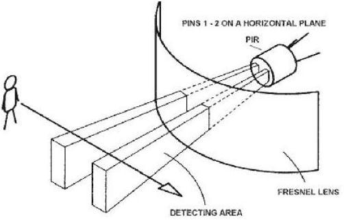
PIR (Passive Infrared sensor) is an electronic component that measures any quite object (person / animal) within the field. The window behind the lens is formed from IR transmissive material. The lens condensesilluminetosome6 7metersanditssensitive. it's a pin’s consisting of VCC, Ground and therefore the Output. The output is given to GPIO pins of ESP 32 CAM MODULE through 5V of power supply to the VCC. It is necessary to detect any intruder as early as possible in orderthatusercantakeimmediateactiontoshieldtheir properties.Thedetectionrangeofanormallow costPIR sensor based system is 10 m but this is often enough to hide most rooms with high ceilings. PIR sensor able to detect sense motion and it ready to detect whether a person'smovementwithinthesensorsrange.
Volume: 09 Issue: 06 | June 2022 www.irjet.net p ISSN:2395 0072
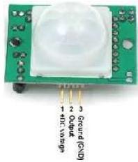
Connecting PIR sensors to a microcontroller is actuallysimple.ThePIRactsasadigitaloutputsoallyou wish to try to is listen for the pin to flip high (detected) orlow(notdetected).it'slikelythatyou'regoingtowant retriggering, so take care to place the jumper within the Hposition!PowerthePIRwith5Vandconnectgroundto ground. Then connect the output to a digital pin i.e. the GPIO pin of the RPI device. A Python code can then be accustomedreadachannelfromthePIRsensor.
Relay is one quite electro mechanical component that functions as a switch. The relay coil is energized by DC in order that contact switches are often opened or closed.onechannel5Vrelaymodulegenerallyincludesa coil, and two contacts like normally open (NO) and normallyclosed(NC).thistextdiscussesanoutlineofthe 5Vrelaymodule&itsworkingbutbeforevisitingdiscuss what's relay module is, first we've got to grasp what's relayanditspinconfiguration.
Pin1 (coil): it's accustomed activate the relay; usually this pin one end is connected to 5Volts whereas anotherendisconnectedtothebottom.
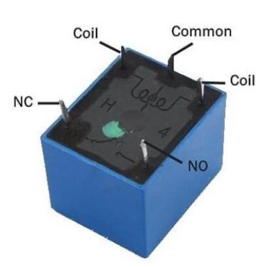
Pin2 (coil): This pin is employed to activate the Relay.
Normally Open (NO): This pin is often open unless we offer a sign to the relay modules signal pin. So, the commoncontactpinsmashesitslink throughtheNCpin tocreateaconnectionthroughtheNOpin
Common Contact: This pin is employed to attach through the load that we desire to modify by using the module.
Normally Closed (NC): This NC pin is connected throughtheCOMpintocreateacircuit.However,thisNC connectionwillbreakoncetherelayisswitchedthrough providing a vigorous high/low signal toward the signal pinfromamicrocontroller.
The primary module within the proposed system is human motion detector. it's accustomed sense the human movements through the hardware available withinthesystem.thiswill beinstalledatentryandexit points like doors, windows, etc. This work is completed by PIR sensor. This may contain different components like resistors, capacitors, IC’s, etc .and therefore the
International Research Journal of Engineering and Technology (IRJET) e ISSN:2395 0056
Volume: 09 Issue: 06 | June 2022 www.irjet.net p ISSN:2395 0072
connected to the ESP 32 CAM module and receive the signalintoPIRsensor.
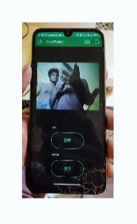
Thefunctionofthesystemtoreceivethesignalfrom PIR sensor and then image will be captured by camera oninbuildwithESP32CAMmodule.Theimagecaptured after send to the Blynk app and also continuous to captured the still images with the comment passes throughtheESP32CAMmoduleconnecttoBlynkserver andBlynkserverconnectedtotheBlynkapplication.The Blynk application used to received captured image and alsopassesthecomment.
Themain processes of a system sendingstill image of captured images to the ESP 32 cam module. ESP 32 cam module is processor and also inbuild wi fi and camera.theESP32cammoduleaftercapturedtheimage issendtotheBlynkapplication Andnotificationsendto the user and These visitors may be known or unknown totheuser.Foranyunauthorized,theownerhastosend commandasopenforenteringintotheresidence.
When the purpose of using the relay its control the electric mini lock. relay connected to the ESP 32 CAM Module processor and then processor connected to the sever and server connected to the Blynk application. WhenusingtheBlynkapplicationtosendthe comments passes through into the processor. Processor send a signaltorelay.Relaysendasignaltoelectricminilock.
The security features of data encryption and the abilitytocreatetheBlynkbotswithseveralfunctionsvia programming code using the Blynk application. The Blynk application processes comments and receives the output of the process and controls the processor with the comment passed through to the processor. when connectingtotheBlynkserveranduploadingcodetothe processor. The server is connected to the Blynk application.
The software used forthis methodused for capturing images is.net files. The programme code for the proposed system uses the Python language. Implementationis thestage of the project when the
theoretical design becomes a working system.This is oftenthe ultimateand most importantinnovation in the systemlifecycle.
Each module in our system will work with flexibility and accuracy. The programmes that were written must be well synchronised in order for the hardware part to work properly. The complete implementation of the system starts from the detection of human movements, and the result is going to be the imagesenttotheBlynkapplication.
1.Initially the hardware part after getting power supply, it will Switches the PIR sensor to detect any intrusion. After detection it'll send signal to the processortoperformfurtheroperation.
2.Theprogramruncontinuouslyandwaitsforthe signal from the processor. When the signal is received fromtheprocessorthesystemcapturestheimage.
3. The captured image send to the server and serversendtotheBlynkapplication.
4. It'll be Send to the Blynk application with the capturedimage.
5.WhentheuserSendthecommandasopenthen onlythedoor otherwiseit'llnotopen.
We have a designed a smart system which reduces the human efforts and provide the ease to operatetheSmartdoor,canaccessitfromanycornerof the world, providing a good security. It is easy to upgrade, portable. The smart door lock system using
International Research Journal of Engineering and Technology (IRJET) e ISSN:2395 0056
Volume: 09 Issue: 06 | June 2022 www.irjet.net p ISSN:2395 0072
Blynk app is very efficient technique, which allows the usertogranttheaccesstotheknownpersonbysending a back message to RPI and unlock the door. The system uses various components like PIR sensor, camera module,switchandBlynkapponanandroidphone.The codingisdoneusingpythonlanguageandinstallationof aBlynkisdoneusingCLIBlynkapp
1.NareshKumarR. SmartDoorSecurityControlSystem Using Raspberry Pi Volume 6, 2347 8616 Issue 11 November2017
2 Reeta R Smart Secure Door Lock System Using IoT And Eigenface Approach, Volume 5, Issue 4 December 2017
3. N. Saravanthi, IoT Based Home Appliance Security System Using Raspberry Pi, Advance and Innovative Research,p.65,2018
4. Shivani Desai Smart Door Security System using RaspberryPiwithTelegramJune2019