International Research Journal of Engineering and Technology (IRJET) e ISSN: 2395 0056

International Research Journal of Engineering and Technology (IRJET) e ISSN: 2395 0056
Viknesvaran C K1 , Priyadharshini P2, Santhosh R J3 , Prakash N4
123Student, Department of Electrical and Electronics Engineering, Kumaraguru College of Technology, Coimbatore, Tamil Nadu, India
4Assistant Professor, Department of Electrical and Electronics Engineering, Kumaraguru College of Technology, Coimbatore, Tamil Nadu, India ***
Abstract - The introduction and production of electric vehicles have created a major impact on automobile sector. Electric vehicles provide more cost efficient and sustainable solutionfor energy consumptionandto reduce the amount of pollution. Establishing accessible and robust network of charging infrastructure is an essential pre requisite in transitionfromconventionaltoElectricvehicles.Theproposed project aims at providing an alternate charging method of electricvehiclesthroughwirelesspowertransferimplemented through inductive power transfer technology.
The proposed system works on the principle of electromagneticinduction.Theimplementationofthesystem is done by interfacing components like transmission and receiving coils, power electronic devices that form the transmission and receiving circuit. On practical implementation on roads this system requires specially designed roads with energized coils buried underneath. Electric vehiclesingeneraltakeaconsiderably longcharging time when compared to conventional vehicles. The proposed method aims to reduce the constraint in charging time and also to provide a future without needing to stop or search resources to charge the vehicle.
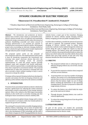
Prototypeoftheproposedchargingmethodwasdevelopedto simulate and analyze the Rate of charging of batteries and efficiency of this method compared to the solutions available.
Transitionfromconventionalvehiclestoelectricvehicleshas become a global factor for reducing the carbon emissions andtryingtoswitchtoalternativeorlessenergyintensive options.Indiaistherankedasthefifthlargestautomobile industry in the world and is currently investing and also lookingforfutureinvestmentinelectricmobilityshift
Duetocommitmenttoglobalclimatechangeandtoreduce the constraints in oil import, India has framed policies to supportthegrowthofE mobility.
TheexistingEVecosystemlacksaccessiblechargingstations, effective battery technology and in terms of market they lackedinvestments.Emergingmarketplayersplayamajor role in the development of this technology and the shift if morelikelytohappenby2030.Chargingfacilitiesforelectric
vehicles forms a major part of the transition. Charging methods for electric vehicles include charging stations, batteryswapping,privateandpublicchargingstations.
Inalltheabovemethodsaconsiderateamountofresources and time is required. The proposed project "Dynamic charging of Electric vehicles" aims to reduce these constraints.methods.Asthemethodchargesthevehicleasit travels along the road, it might not require to stop for charging stations. The battery forms and contributes the mostinE vehicles,theproposedmethodtendstoreducethe batterysizewhichreducesthesizeofthevehicle.Heavyduty vehicles that carry huge amount of load and carry long distancesbenefitsthemostfromthetechnology.
The proposed method aims in achieving fast and efficientchargingwithoutanycostoftime,money, scalability.
Toprovidelessexpensivesolutionwhencompared withthecurrentsolutions.
Atpresentthereareverylessnumberofcharging stations.Thereasonisitisadevelopingtechnology andalsothereisafearorinconvenienceamongthe drivers that the battery might run out of charge before reaching the destination or the upcoming chargingstation.Theideaisproposedtoreducethe rangeanxietyofdrivers.
To reduce the battery size which holds the major partinthetotalcostofvehicle.
Through dynamic charging battery size could be reducedsignificantly.
Toreducetheenergybeingdrawnfromthegridfor directcharging.
As part of the survey, we studied the practically implementedelectrifiedroadsinSweden.Theprojectisbuilt asdemonstrationsiteforelectricroads.
Volume: 09 Issue: 05 | May 2022 www.irjet.net p ISSN: 2395 0072 © 2022, IRJET | Impact Factor value: 7.529 | ISO 9001:2008 Certified Journal
International Research Journal of Engineering and Technology (IRJET) e ISSN: 2395 0056
Volume: 09 Issue: 05 | May 2022 www.irjet.net p ISSN: 2395 0072
Electrified road system that allows electric vehicles to be chargedfromtheroadwasbuiltandimplementedtotestthe behavior of electric vehicles on them. The electrified road systemwasalsotestedtocheckiftheycouldadaptclimate smarttechnology.
• Wireless charging stations implemented in Norway was studied. Charging was done wireless using induction technology.Chargingplatesinstalledinthegroundcharges thebatteriesoftheEVtaxisviareceiverinstalledinthem. Thetaxisareparkedabovethechargingplatesandcharged usingstaticcharging.
• From the data studied on energy consumption, carbon emissionandemissionintensityofconventionalvehicleswe couldestimatethattheproposedprojectreducesall these constraints The “E Mobility” published by the Bureau of energy efficiency, Government of India Ministry of power wasreferredtounderstandthepoliciesframedondifferent statesofIndia.
• The article “Handbook for EV charging infrastructure implementation” by Bureau of energy efficiency, Government of India, Ministry of power was referred to knowtheEVcharginginfrastructureroadmap,EVcharging requirements, location planning and arranging electricity supplytomodelsofongroundimplementation.
TheAlternatingcurrentisprovidedfromthesourcethatis thegridtothetransmittercircuitplacedintheroadorinthe pavementoftheroad.Asthepoweristransferredwirelessly using inductive power transfer method, we might need alternating current of high frequency for effective energy transfer.The50hzACprovidedfromthemainsisrectified firstthatisthatisalternatingcurrentisconvertedtodirect current.
Then to convert the direct current from the rectifier to alternating current of high frequency, power electronics basedinvertercircuitisused.ThehighfrequencyACwaveis suppliedtotheprimarycoil.
The alternating current supplied in the primary coil produces alternating flux and this flux gets linked to the secondary coil. There will be an induced emf in the secondarycoilduetoelectromagneticinduction Asthecoils wereseparatedbyairgaptheprimaryandsecondarycoils arelooselycoupled TheAcoutputreceivedinthesecondary coilisagainrectified(convertedfromACtoDC)andstored inthebatteryoftheElectricvehicle.
International Research Journal of Engineering and Technology (IRJET) e ISSN: 2395 0056
Volume: 09 Issue: 05 | May 2022 www.irjet.net p ISSN: 2395 0072
Bridge rectifier:
BLOCK A: Transmittercircuitplacedontheroad
BLOCK B: Receiver circuit with storage placed on the Electricvehicle.
BlockAofthediagramrepresentsthetransmittersideandit consistsofpowersource,Transmitterpowerelectronics,and transmittercoilarray.ThePowersourceisprovidedfrom the grid in practical implementation. The transmitter side power electronics circuit rectifies the AC input to DC. The capacitorplacedfilterstheDC.IntheinvertercircuitDCto ACconversiontakesplaceandthefrequencyisincreasedfor transmission.
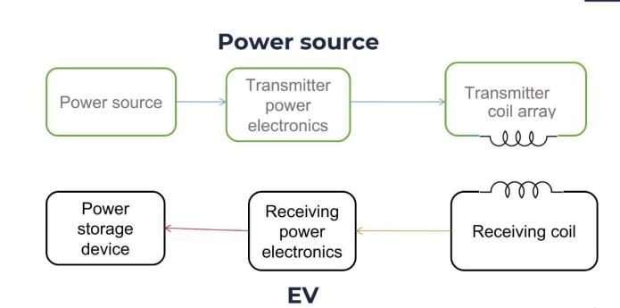
Block Bofthediagramrepresentsthe receiversideand it consists ofreceivingcoil, receivingside powerelectronics andpowerstoragedevice.TheACpoweristransferredfrom thetransmittertoreceiverthroughthereceivercoil.Inthe receiversidepowerelectronicscircuitACtoDCconversion takes place and the Voltage is stepped down in a way suitableforstoringinthebattery.
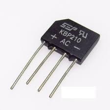
Bridge rectifier circuit converts the incoming alternating current to direct current. Bridge rectifiers are circuits consisting of four or more diodes arranged in the bridge circuitconfiguration.Theoutputwaveisofthesamepolarity irrespectiveoftheinputpolarity.
TheBridgerectifierrectifiesthesuppliedACvoltageatthe sourcetoDCvoltageinthetransmittersideandrectifiesthe ACvoltageatthereceiversidetoDCvoltage.
Polarized Capacitor:
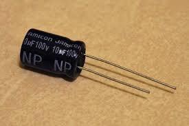
Polarizedcapacitorsareusedinthetransmittersidetofilter outtherectifiedDCoutput.Inreceiver
Side they are used to filter out the DC output from the rectifierandthenpassittothebattery.
International Research Journal of Engineering and Technology (IRJET) e ISSN: 2395 0056
Volume: 09 Issue: 05 | May 2022 www.irjet.net p ISSN: 2395 0072
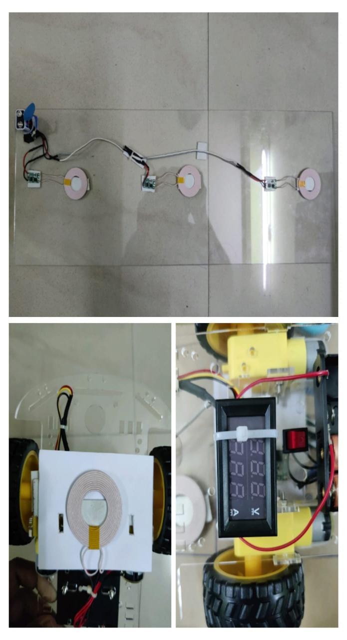
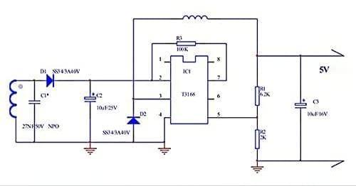
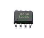
T5336 11025 IC:
This IC has an operating voltage of 5V 12.0V operating voltage and an operating current of 1.2A 2.0A operating current. It has an operating frequency of about 70Khz 110Khz.Itisplacedonthetransmittersideofthedynamic charging circuit and converts the Direct current to alternatingcurrentandproduceshighfrequency.
XKT408A1215A IC:
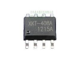
This IC has an operating voltage of 5V 12.0V operating voltage and an operating current of 1.2A 2.0A. It has an operatingfrequencyofabout70Khz 110Khz.Itconvertsthe alternatingcurrenttodirectcurrentandactsasanamplifier.

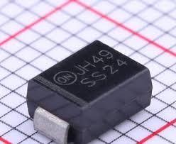
Ithasmaximumvoltagelimitof40Vandmaximumcurrent of 1.2A to 2A. It converts the alternating current to direct currentandactsasvoltagerectifier.
Intheprototypebuiltlithiumionbatteryof6Vcapacityis used as the voltage source. It is connected to the receiver sideofthecircuit.
Transmitting Coil and Receiver coil:
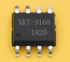
This IC has an operating voltage of 3.0V 15.0V operating voltageandanoperatingcurrentof1.0mA 10.0Aoperating current.ItamplifiestheDCvoltageandcurrent.
T3168I2022 IC:
FortransmittingandreceivingAmericanwiregaugecoilthat iscoppercoilofsize20mmisused.Thethicknessofthecoil isabout2.3mm,theinnerdiameterisabout43mmandouter diameterisabout20mm.Thetransmittercoilisdesignedin suchawayitislongerthanthereceivercoiltoreducethe cost and this results in coupling coefficient between the transmittercoil andreceivercoil.
International Research Journal of Engineering and Technology (IRJET) e ISSN: 2395 0056
Volume: 09 Issue: 05 | May 2022 www.irjet.net p ISSN: 2395 0072
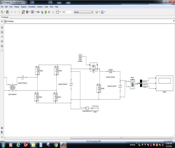
Thepowertransferfromthetransmittertoreceiversidein lineartransformerissimulatedusingMATLABtoshowthe simulationofinductivepowertransferbetweenthecharging coilsintheroadthebatteriesofelectricvehicle.Itconsistsof transmittercircuit,receivercircuitandthetransfercoils.
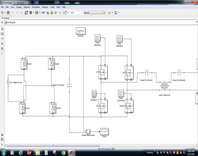
Transmitter:
ThesupplyisprovidedusinganACvoltagesourceof230V, 50HZ.ThesourceisconnectedtotheBridgerectifierwhich rectifiestheACinputtoDC.ThediodesD1,D2,D3,D4are arrangedinthebridgecircuitconfiguration.D1andD2are forward biased to rectify the positive sine wave and the diodesD3andD4are
reversebiasedtorectifythenegativesinewave.Theseries RLCbranchisusedtofiltertheDC.TherectifiedDCoutputis fed to the inverter circuit. The inverter is formed by arranging the S1, S2, S3 and S4 MOSFET switches. The switchesS1,S2andS3,S4areswitched(S1,S2ONandS3,S4 OFF) alternatively using pulse generator to produce alternating current of high frequency. The two modes of switchingare:
1)InthefirstmodeS1andS2areinONstate,S3andS4are inOFF state. When S1and S2areinONmodethecurrent flows from the switch S1 to the positive side of the load. From positive side current flows to the negative side and thenflowstotheswitchS2.
2)InthesecondmodeS3andS4areinONstate,S1andS2 areinOFFstate.Inthismodecurrentflowsfromtheswitch S3tothenegativesideoftheload.Fromthenegativeside currentflowstothepositivesideoftheloadandthenflows to the switch S2. For switching sinusoidal pulse width modulationtechniqueisused.
Thevoltagetransferfromtheprimarysidetothesecondary sideisdoneusingthetransformer.
The transferred AC voltage from the primary side is then passed through a capacitor and then fed to the rectifier circuit.
Therectifiercircuitisformedbyarrangingthefourdiodes. ItrectifiestheAlternatingcurrenttodirectcurrent.
A diode, capacitor, MOSFET switch, and an inductor are arranged to form the buck converter. The buck converter stepsdowntherectifiedDCvoltageforchargingthebattery.
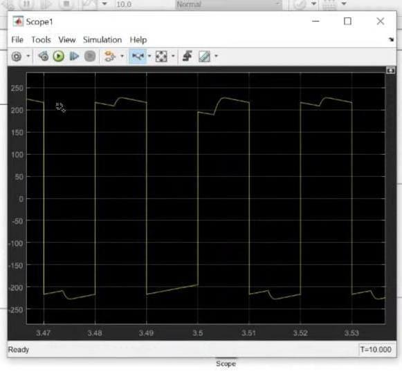
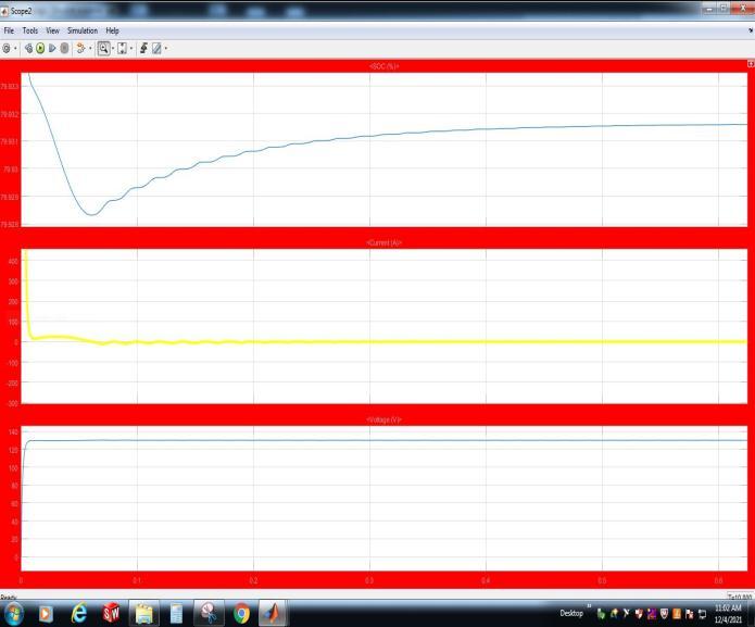
The bus selector is connected to the battery to select the batterysignal.TheStateofcharging,currentandvoltageis knownfromthescopeconnectedtothebusselector.
International Research Journal of Engineering and Technology (IRJET) e ISSN: 2395 0056
Volume: 09 Issue: 05 | May 2022 www.irjet.net p ISSN: 2395 0072
their system designs have been focused on proving the reliabilityofthesystemsratherthanoneconomicvalues.
Althoughwirelessdynamicchargingisstillinitsearlystages of development, it is likely to become one of the most essential solutions for meeting the growing need for charging infrastructure within next years. Although extra expendituresindynamiccharginginfrastructurewouldbe madeduringtheinstallationstage,wediscoveredthatthe longerbatterylifecansavesignificantlymoremoney.
[1] Reviewofstaticanddynamicwirelesselectricvehicle chargingsystemChiragPanchal,SaschaStegen,JunweiLu Griffith School of Engineering, Griffith University, NathanCampus,Brisbane4111,Australia.
[2] T.batra,‘‘DesignofStaticWirelessChargingSystemfor ElectricVehicleswithFocusonMagneticCouplingand Emissions,”DoctorofPhilosophyPh.D,Departmentof Energy Technology Aalborg University, Aalborg University,2015.
[3] Costanzo, A.; Dionigi, M.; Masotti, D.; Mongiardo, M.; Monti,G.;Tarricone,L.;Sorrentino,R.Electromagnetic EnergyHarvestingandWireless.
[4] Power Transmission: A Unified Approach. Proc. IEEE 2014,102,1692 1711.
[5] Kuncoro, C.B.D.; Sung, M. F.; Kuan, Y. D.; Battery Charger Prototype Design for Tire Pressure Sensor Battery Recharging. Sensors 2019, 19, 124, doi:10.3390/s19010124.Garnica,J.;Chinga,R.A.;Lin,J. WirelessPowerTransmission:FromFarFieldtoNear Field.Proc.IEEE2013,101,1321 1331.
This concludes the overview of the dynamic wireless charging EV system. We concluded that the dynamic charging system is more beneficial for large scale EV systems and the battery costs could be significantly reduciblewhenthepowertrackcostdrops.Althoughthere are some commercialized dynamic charging EVs, they are still in the very early stages of the commercialization and