International Research Journal of Engineering and Technology (IRJET) e ISSN:2395 0056

Volume: 09 Issue: 06 | June 2022 www.irjet.net p ISSN:2395 0072
International Research Journal of Engineering and Technology (IRJET) e ISSN:2395 0056
Volume: 09 Issue: 06 | June 2022 www.irjet.net p ISSN:2395 0072
Shriram J. More1, Prof. Jamil M.
Dabir2
1Mechanical Engineering Department, Walchand College of Engineering, Sangli.
2 Mechanical Engineering Department, Walchand College of Engineering, Sangli. ***
Abstract Finite Element Method (FEM) as a numerical method is widely used as a calculation method in the field of engineering analysis, it gets widely developed with its unique advantages of computing, ANSYS software with its multi physics field coupled analysis function has become mainstream of software applications and it is widely used in the engineering analysis. At the same time ANSYS software has powerful features dealing with thermal analysis; Mill roller, shaft and shell are assembled by shrink fitting method. In that case interference fit is generated. After some cycles the shell of mill roller is wear out. For better performance we have to re machine the mill roller. Conventional dismantling method is difficult and very expensive. To provide experimental solution for this problem is very costly and time consuming procedure. So, there is need to do analysis on mill roller. For that drawn the 3D model according to 2D drawing. Did the manual meshing using body sizing command. As not getting the results so did geometry refinement process and find out the meshing properties i.e., skewness and orthogonal quality. Doing analysis of separation condition for shrink fitting of existing mill roller in Ansys by cooling the shaft of a mill roller at 10°C in cooler chamber by using ice cubes or liquid nitrogen. Heating the shell of the mill roller at 400°C in a furnace by giving or introducing supports to avoid no constraints error. Then at what cooling and heating temperature the assembly of shaft and shell of the mill roller gets separated needs to find out. Numerical results will be validated by using Analytical method.
Key Words: Shrink fit, Skewness, Orthogonal quality, ANSYS, FEM.
Mill roller shells are among the main assembling linecomponentsinthesugarproductionprocess.Theyare painstakinglyplannedbymanysurfacerulesamongwhich wearresistanceisthemostsignificant[1] Toincreasethe lifeofthemillrollershells,theresistanceofthesurfaceto failurebyabrasionshouldbeincreased.
Ashrink fitisasemi permanentassemblysystem between two parts without utilizing another fastening device. It gives a minimal expense strategy to attaching parts and is generally utilized in industry, with applicationsto cuttingtoolholders,wheelsandbandsfor railway stock, gears, turbine discs, rotors for electric
motors and for locating ball and roller bearings. The underlying principle involves establishing a pressure between the inside diameter of a part such as a hub and the outside diameter of a shaft through interference in dimensions at their radial interface [2]. Commonly, expansionoftheexternalpartbyheating orcoolingofthe shaft is utilized, The parts are found and afterward the entire assembly is gotten back to the working temperature,whereuponthepressurekeepsuphighwith part area (resistance to pressure or compression) and additionallypermitstransmissionofatorque.
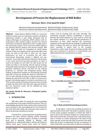
Fig 1: Assembly procedure of shaft and shell of mill roller.
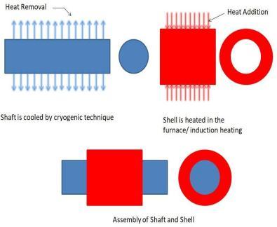
As the figure 1 shows the assembly procedure of shaftandshellofmillroller.Theshaftiscooledbyremoval of heat using cryogenic technique in which this shaft is kept in the ice box of liquid nitrogen for cooling purpose. Thenshellofmillrollerisheatedinthe inductionfurnace. Once it reaches to certain temperature the shell of mill rollerexpands,atthattimetheshaftisinsertedintheshell while this process is happening and due to expansion of shellofmillrollerandcontractionofshafttheassemblyof
International Research Journal of Engineering and Technology (IRJET) e ISSN:2395 0056
Volume: 09 Issue: 06 | June 2022 www.irjet.net p ISSN:2395 0072
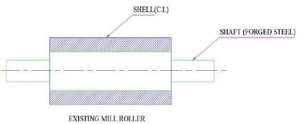
both takes place simultaneously. In figure 2 conventional dismantlingprocedureofshaftandshellofmillroller,the shellofmillrolleriscutdownandshaftisreused.Thecut downpartofshellofmillrolleristhenwasteorscrap.
The static structural analysis of roller shaft is carried out using analysis software ANSYS Workbench. Theresultsformaximumshearstressonthetop,Feedand Discharge roller are calculated analytically and compared with the results from software. R. K. Jain [3] briefly discussed tolerances and its importance. In this paper explained interchangeability thoroughly. Also described differenttypesoflimitswiththeexamples.Crawford,W.R. [4] presented known theories for shell shrink (interference)fitswithregardtostressesinducedandalso shrinkfitsrequiredtoensuredesiredmillrolleroperation. Mr. Crawford stated that the essential requirement of the shrink was to ensure that the friction between the shaft and shell was sufficient to transmit the torque necessary for crushing, including transient torque peaks and the reduction in transmittable torque due to roller wear. Walmiki S Rathod [5] has presented work related to two roller sugar mill using FEA technique. They have calculated bending moment analytically and by software. Alsohavegivenresultsthattapergiveslessvalueofstress thanthefillet.R.V.Ramachandran[6]wasoneoftheearly investigators to study the influence of surface finish on interference fits. The materials used for shrink fits were mild steel for both the hub and the shaft. The bore in the hub was reamed in all cases with a suitable reamer. The shaft finish was varied using different processes such as course/fine, turning and grinding. He found that the load carryingcapacityofthepressandshrinkfittedassemblies, among other factors, depends appreciably on the roughness of the mating parts. The results show that, in general,surfaceswithfinefinishescancarryhigherloads. However, in case of shrink fits,above a certain roughness the load carrying capacity increases with roughness. Where Interference fits are to be dismantled and resembled;finersurfacesarecapableofmaintainingtheir loadcarryingcapacity. None of the commonly established a geometrical roughness parameters are very useful in describingtheeffectofroughnessoninterferencefits.
Shaftandshellofthemillrollerareassembledby shrink fitting method. In that case interference fit is generated.Aftersomecyclestheshellofmillrolleriswear out. For better performance we have to re machine the mill roller. Conventional dismantling method is difficult and very expensive. To provide experimental solution for this problem is very costly and time consuming procedure.So,thereisneedtodoanalysisonmillroller.
Theproposedworkincludedfollowingsteps:
1)To study assembly procedure and conventional
dismantlingprocedureofmillroller.
2) To do numerical analysis of separation conditions forshrinkfittingofexistingmillrollerinANSYSsoftware.
3)To give solution for the problem and do numerical analysisforthesame.
4)To compare or check the results of analysis and commentonthesame.
Finite Element Method (FEM) is a computer based numerical technique for calculating the Strength and behavior of engineering structures. It can be used to calculate deflection, stress, vibration, Buckling behavior andmanyotherphenomena.Inthefiniteelementmethod, astructureisbrokendownintomanysmallsimpleblocks orelements.Thebehaviorofanindividualelementcanbe describedwitharelativelysimplesetofequations.Justas the set of elements would be joined together to build the whole structure, the equation describing the behaviors of theindividualelementsarejoinedintoanextremelylarge set of equations that describe the behavior of the whole structure.Thecomputercansolvethissetofsimultaneous equations. From the solution, the computer extracts the behavior of the individual elements. From this, it can get the stress and deflection of all the parts of the structure. Thestresseswillbecomparedtoallowedvaluesofstress.
1. Discretizationofthedesign. 2. Selection of appropriate addition or removal model.
Derivation of element stiffness matrices and load vectors.
Solutionfortheunknownnodaldisplacements.
Computationalelementalstressandstrains.
Metalsordinarily expandwhenheatedand contractwhen cooled.Thisreactiontoachangeoftemperatureisknown as thermal extension. With induction shrink fitting, use thermal expansion to fit or remove parts. A metal part is warmed to 150 400 °C (305 752°F), and that makes it to expand.Thisallowstheremovalorinsertionofa part.for example, for disassembly the induction is used to create thermal expansion for loosning of thejoint.Forassembly,
International Research Journal of Engineering and Technology (IRJET) e ISSN:2395 0056
Volume: 09 Issue: 06 | June 2022 www.irjet.net p ISSN:2395 0072
one part might be heated until its diameter expands sufficientlyforittofitovertheotherpartoftheassembly. Then,theheatedpartcoolsandthejointgetstrong,which is “shrink fitting.” A wide array of metals is used when shrink fitting, whether it's steel to steel, steel to copper, aluminum to steel, etc. Crushing roll shells are currently shrink fitted onto roll hubs by heating the shell until it expands,slidingit ontothe huband letting itcool,sothat theshellshrinkstightlyontothehub.Crawford(1970)[4] presented known theories for shell shrink (interference) fits with regard to stresses induced and also shrink fits required to ensure desired mill roller operation. In this paper stated that the essential requirement of the shrink fit was to ensure that the friction between the shaft and shell was sufficient to transmit the torque necessary for crushing, including transient torque peaks and the reduction in transmittable torque due to roller wear. Crawford, using simple interference fit theory, calculated the tensile hoop stresses, compressive radial stresses and axial stresses induced in the shell. The relationships between material parameters and shell geometry on induced shell stress and transmittable torque were plotted.
Table 1: Composition of Shaft material
Carbon,C 0.37 0.44% Iron,Fe 98.6 99% Manganese,Mn 0.60 0.90% Phosphorus,P <=0.040% Sulfur,S <=0.050%
Table - 2: Composition of
Totalcarbon 3.2to3.6 percent Sulphur 0:15percent, Max Phosphorus 0.5percent, Max Manganese 2.2to3.2percent Silicon 1.2to2.2 percent
Table - 3: Shaft AISI 1040 Material Properties [8]
Density
7845kg/m3
TensileStrengthUltimate 620mpa TensileStrengthYield 415mpa
ModulusOfElasticity 200gpa BulkModulus 160gpa
Poisson'sRatio 0.29 ShearModulus 80gpa
ElectricalResistivity 0.0000493ohm cm Coefficient of Thermal Expansion (CTE) 13.3μm/m℃
SpecificHeatCapacity 0.586j/g℃ ThermalConductivity 50.7w/mk
Table 4: Shell AISI 1030 Material Properties [9]
Density
7850kg/m3
TensileStrengthUltimate 525mpa
TensileStrengthYield 440mpa ModulusOfElasticity 200gpa BulkModulus 140gpa Poisson'sRatio 0.285 ShearModulus 80gpa
ElectricalResistivity 0.000034ohm cm CoefficientofThermal Expansion (CTE) 11.7μm/m℃
SpecificHeatCapacity 0.223j/g℃ ThermalConductivity 51.9w/mk
Optimization of a designing plan is an improvement of a proposed plan that outcomes in the best properties for least expense. Perhaps the simplest examples is determiningtheshapeofafencethatwillenclosethemost area. On the off chance that the wall can be any shape, however just a specific measure of fencing is accessible, then, at that point, a circle will encase the most region withthegivenmeasureoffencing.Tolimithowmuchsteel utilizedinassemblingabarrelshapedmetalcanaspecific connectionbetweenthedistanceacross canandthelevel ofthecanisfound.Thiswillencaseavolumewithminimal measureofsteelutilizedforthesurfaceregion.
International Research Journal of Engineering and Technology (IRJET) e ISSN:2395 0056
Volume: 09 Issue: 06 | June 2022 www.irjet.net p ISSN:2395 0072
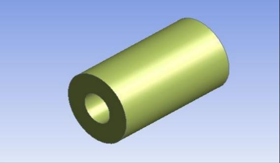
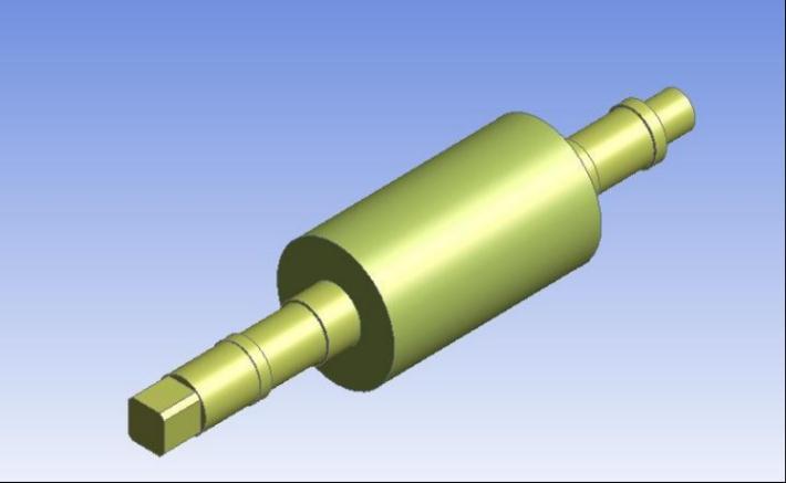
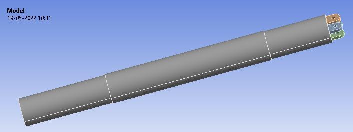
For mathematical review 3D model of shaft and shell is required.Geometryofshaftandshellwasmadeaccording to real aspects utilizing Ansys Design Modeler. Figure 3 Shows 3D model of shaft. Geometry is drawn in Ansys DesignModelerin3Daspertruescale.
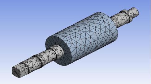
namedasAISI1040forshaftandAISI1030forshellofthe mill roller. Thermal stress analysis were performed by using the general purpose package software ANSYS, producedbyANSYSInc.Meshingistheprocessofturning irregular shapes into more recognizable volumes called elements. Before start meshing, we must first upload a geometryormodelinto,forexample,Ansysmechanicalto begin the meshing process. It is also process in which the continuous geometric space of an object is broken down into thousands or more of shapes to properly define the physical shape of the object. The more detailed any mesh is, the more accurate the 3 D model will be, allowing for high simulations. Figure 5 shows meshing of assembly usingautomeshcommandandfigure6givesdetailsabout meshqualityspectrum.
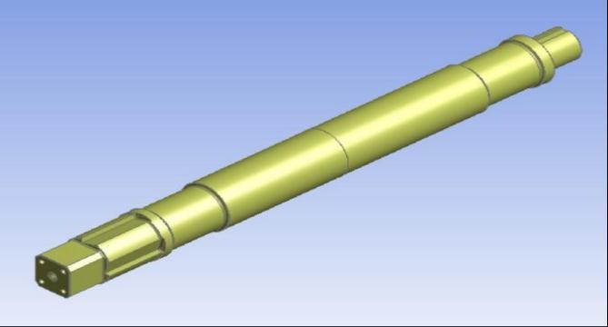
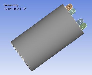
Theuseofcontactalgorithmtodetectthepenetrationand apply contact forces to push the parts apart until there is no more penetration. Figure 4 shows the actual assembly drawingofshaftandshell.
Steady state thermal stress analysis were executed to study the thermal stress effect of on the shaft and shell various materials. The variations of temperature and thermal stress on the parts are investigated for materials

Skewness is the difference between the state of the cell andthestateofa symmetrical cell ofcomparablevolume. Highlyskewedcellscandecreaseaccuracyanddestabilize the solution. Figure 6 gives the details of mesh quality spectrum where we get acceptable and unacceptable values of skewness mesh. Figure 7 shows auto mesh skewnesswhereminvalueis0.0031979andmaxvalueis 0.98263 which is unacceptable according to mesh quality spectrum.
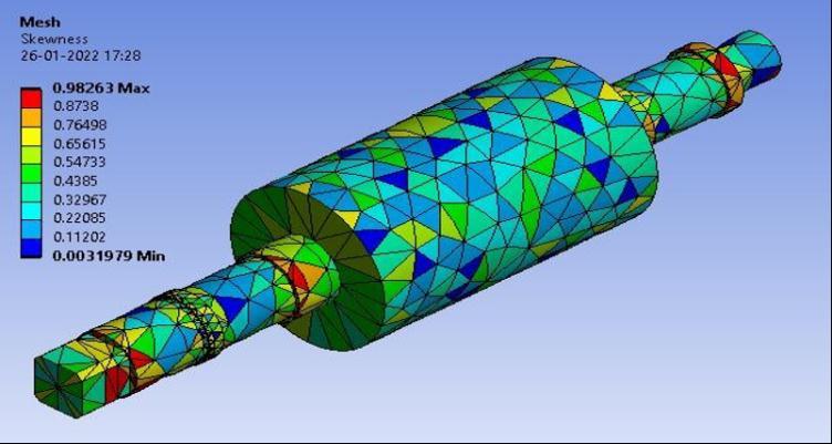
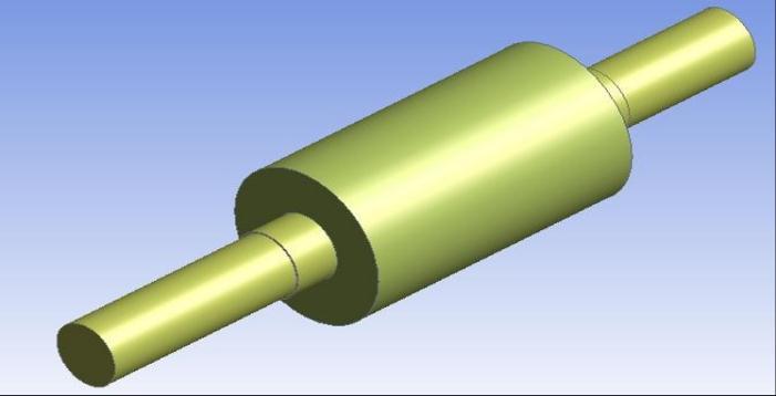
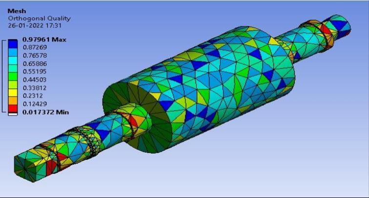
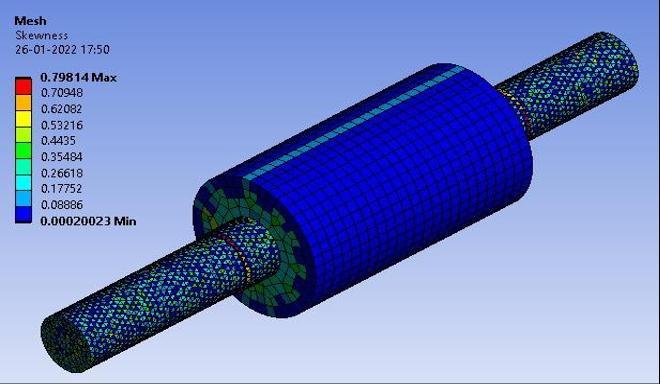
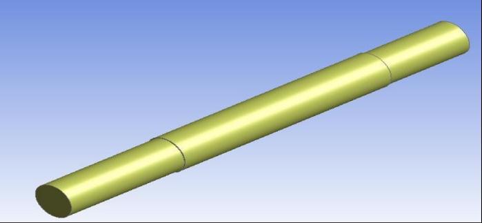
Fig 7: Skewness
OrthogonalQualityislikewisecommonlyusedtoevaluate the mesh shape quality as skewness of mesh structure. It sounds complex but what we need to know about “OrthogonalQuality”is,0isworstand1isthebest.Figure 8showsautomeshorthogonalqualitywhereminvalueis 0.017372 and max value is 0.97961 which is unaccepted accordingtomeshqualityspectrum.
As we do not get the actual result as we expected from auto mesh and manual mesh, We chose to do refinement tocomebydefiniteoutcomewhichneed.Inthisisneeded eliminate 1mm edges, steps, by refining other parts by making it same size as they are undersize of the interference fit value. Figure 9 shows refined shaft geometry and figure 10 shows refined shell geometry, we also remove the steps in the shell for better to get results inmeshingandanalysis
Tochecktheskewnessvalueofrefinedmeshgeometrywe have to run the Mesh command then mesh metric shows theskewnessvaluei.e.,0.00020023minand0.79814max that it is in good condition according to mesh quality spectrum figure 6. The skewness value of refined geometryisshowninfigure11.
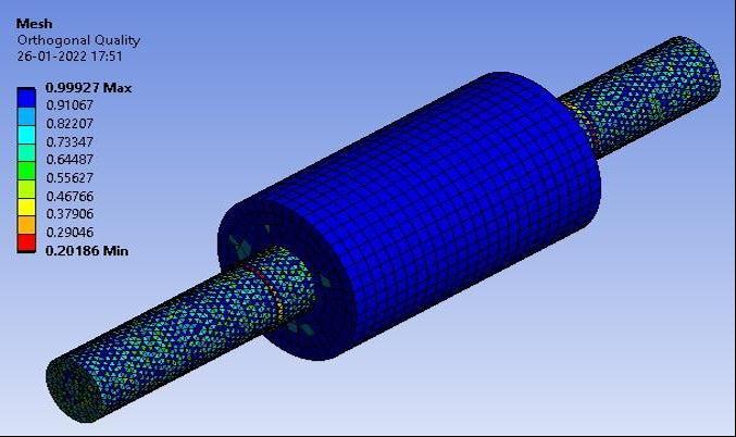
After skewness by checking orthogonal quality of refined geometryitgives0.20186minand0.99927maxthatisin excellent condition according to orthogonal mesh quality spectrum. figure 12 shows orthogonal quality of refined geometry.
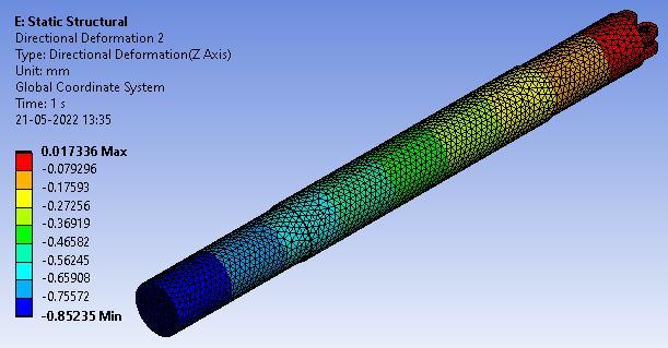
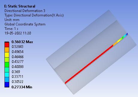
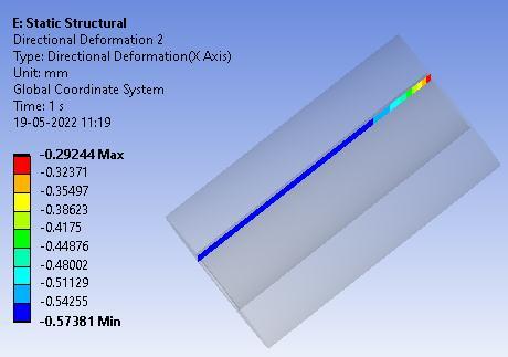
Asthemeshingofrefininggeometrydonethenneedtodo analysis of existing mill roller at seperate conditions for that tentative supports introduced. Taking the shaft first andcoolingitat 10℃inaiceboxorusingliquidnitrogen asshownin figure 13. Solvingthesolution insteadystate thermal importing its results into static structural where we could find out directional deformation through shrink fitlengthandafter running the solution got the results as the shaft gets shrink or contracted by 0.84mm as shown in figure 14. Figure 14 (a) and (b) gives the information aboutdeformationattheedgethroughoutlength.
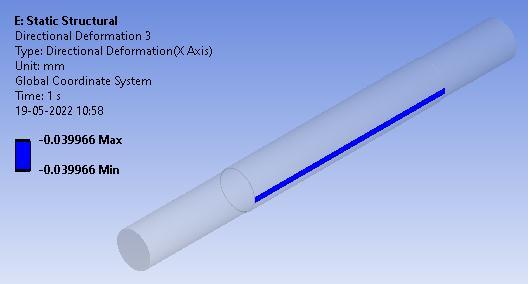
(a)
(b) (c)
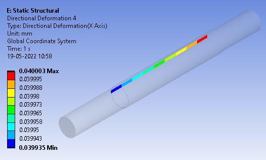
After Shaft analysis is done the shell analysis using supports as shown in fig 15. Now here used heating processwhereshellisheatedat400℃inpittypefurnace.
Now solving the solution in steady state thermal and importingitsresultsintostaticstructural.Aftersolvingthe solution in static structural it gives directional deformation at edge throughout length in figure (a) and (b). By heating the shell at 400℃ it gets expanded by 4.67mmasshowninfigure(c).
International Research Journal of Engineering and Technology (IRJET) e ISSN:2395 0056
Volume: 09 Issue: 06 | June 2022 www.irjet.net p ISSN:2395 0072
[3] R. K. Jain, Limits, Fits And Gauges, R. K. Jain, Engineering Metrology, Khanna Publishers, New Delhi, 261 362,2009.
[4] Crawford, W.R. “Roller shells and the shrink fit”, Proe. Qld. Society Sugar Cane Teeno!., 37,323 339,1970.
[5] Chetan T Rathod, Walmiki S Rathod, “Design and Analysis of Two Roller Sugar mill using FEA Techniques”, International Journal of Scientific Engineering and Technology, Volume No.1, Issue No.3, 148 152,2012.
[6] R. V. RAMACHANDRAN and V. RADHAKRISHNAN, “Influence of surface finish on interference fits”, International Journal of Production Research, VOL. 12, NO.6,705 719,2007.
[7] Matweb Material Property Data, matweb.com, http://www.matweb.com/search/DataSheet.aspx?Mat GUID=c8ada14779744d008a6c3 e80f035c5d5&ckck=1,Jan17,2022.
[8] BBN Steel Store, steelstores.com, https://www.steelestores.com/grade/is grade 280 520w is 1030.html,Jan20,2022.
ThedeformationofFEMshaftandshellofthemillrolleris calculatedusingsteadystatethermal andstaticstructural process. Static structural process is more efficient for measurement of directional deformation of mill roller parts, as it is numerical, non contact and reliable method. It can be concluded as static structural process has middle level accuracy and provides results with acceptable tolerance. The proposed system gives the resultsinlesstimecomparedtoconventionalmethodthat isused in the industriesso itcan beused to measureand analysethedirectionaldeformationofthespecimen.
[1] E.E.T.ELSawyc,M.R.EL Hebearya,I.S.E.ElMahallawib, “Effect of manganese, silicon and chromium additions on microstructure and wear characteristics of grey castironforsugarindustriesapplications”, Wear, 113 124,2017.
[2] JulianD.Booker,ChristopherE.Truman,SWittigandZ Mohammed, “A comparison of shrink fit holding torque using probabilistic, micromechanical and experimental approaches”, Journal of Engineering Manufacture 218(2):175 187,2004.
[9] Fenhua LI, Jian XING,Yuan LIU, “Thermal Analysisand Stress Analysis of the Heat exchange Pipe Based on ANSYS”, Fourth International Conference on Information and Computing, 283 285,2011.
[10] Chetan T Rathod, Walmiki S Rathod, “Design and Analysis of Two Roller Sugar mill using FEA Techniques”, International Journal of Scientific Engineering and Technology, Volume No.1, Issue No.3, 148 152,2012.
[11] Lijesh K.P., “Finite Element Analysis of Flywheel Considering Interference Fit”, International Journal of Emerging Trends in Engineering and Development, Issue5,Vol.6,163 170,2015.