Volume: 09 Issue: 06 | June 2022 www.irjet.net p ISSN:2395 0072


Volume: 09 Issue: 06 | June 2022 www.irjet.net p ISSN:2395 0072
Dr. Venugopal P4
1,2,3Student, Vellore Institute of Technology, Vellore, Tamil Nadu 4Professor, Vellore Institute of Technology, Vellore, Tamil Nadu ***
ABSTRACT: The battery management systems also referred to as BMS is a battery management unit that is not only responsible to measure the state of battery accurately, but it also ensures safe operation and also a prolonged battery life. Because of their high energy density,lifespan,nominalvoltage,powerdensity,andlow cost, lithium ion (Li ion) batteries have received a lot of attentionintheEVindustry.Asmartbatterymanagement system (BMS) is an essential component in electric vehicles it not only measures the states of the battery accurately,butitalsoensuressafeoperationandextends battery life. Estimating the state of charge (SOC) of a Li ion battery accurately is difficult due to the battery's highly time variant, non linear, and complex electrochemical system. So in this paper we will study about the various parameters related to battery performance like the state of charge, state of health and also look at over charge and under charge circuits that weredesignedtomonitorthebatteryhealth.
KEYWORDS:Stateofcharge,stateofhealth,lithiumion batteries,matlab.
The lithium ion batteries that are used now a days are very fragile in nature when compared to lead acid, or NiCd batteries which makes them useful in various applications like cell phones or industrial equipment etc. these lithium ion batteries that are used, needs a management system to monitor its health by calculating various parameters. The complexity of any battery management system totally depends on the type of application for which this system has to be designed. for applications like mobile phones or e book readers etc, a simple BMS IC can be used, this IC will monitor the voltage,current,stateofchargeandvariousother parameters. these parameters will give us the overall health of the battery. But for bigger applications like electronicvehicles,weneedabetteralternative.Anormal IC won’t be sufficient. We need very high end algorithms and processing to measure various parameters. We will go through these in detail as we move further with our paper.
First in this paper we will go through various battery management system requirements in detail to understand how can we actually optimise the performanceofthelithiumionbatteriesinanysystem.
Several factors must be considered when designing a bms. There are various Relevant parameters include temperature acquisition, voltage and current acquisition, batterypacketcthatareimportanttoensureproperEMI robustness, functional safety in terms of redundancy, galvanicisolation,balancing,andpowerconsumption.
Temperature acquisition: One of the most difficult tasks in BMS design is determining the most accuratetemperature possible. It is sometimes necessary to obtain peripheral temperatures, such as those of contactors, fuses, or even the electric busbar. Heavy copper bus bars should be avoided as much as possible. Temperature requirements must take into account three use cases: charging, discharging, and storage. Temperature sensor to voltage sensor channel ratios typicallyrangefrom2:3to2:12.Attoohighcurrentrates, the significant effect of lithium plating can occur in the normaltemperaturerange.
Voltage acquisition: A battery management system for lithiumbasedbatteriesneedstohaveatleastonevoltage acquisition channel per serially connected cell. High data acquisition rates are advisable, if oversampling is chosen to have a positive effect on the system behaviour. When largepulsesoccurinanapplication,fastermonitoringcan benecessary.
Current acquisition: For dynamic SOC determination, coulombcounting isused. This methodsimplyintegrates the current flowing into or out of a battery. The determinedSOCwillbedifferentfromtheactualSOCdue to noise and offsets. There are approaches using algorithms and parametrised models to retrieve usable SOCvalues.
Balancing:Thereareseveralfactorsthathavetobetaken care of before a battery can be charged and discharged, e.g., resulting from weight constraints, or required chargingcurrentsthatleadtobalancingcurrents.
International Research Journal of Engineering and Technology (IRJET) e ISSN:2395 0056
Volume: 09 Issue: 06 | June 2022 www.irjet.net p ISSN:2395 0072
So in this paper our main objective is to study about the thestateofchargeandstateofhealthofthebattery.Once studied, the simulation results are then observed using MATLAB (Matrix Laborotory). The flow of the paper will be such that we will first Monitor the cell voltage and temperature.Thenthevaluesofstate of chargeandstate of healthareestimated.Oncethatisdoneforthosevalues we will limit thepower input and output for thermal and overchargeprotection.
As lithium ion cells are used so we need to balance the stateofchargeoftheseindividualcells.Afterthisisdone we need to isolate the battery pack from the load whenever necessaryto avoidunnecessaryloadingeffects inthecircuit.Thentheentiredesignwasimplementedon the software using MATLAB and Simulink. Once the simulation was done, the algorithm was deployed on a raspberrypimicrocontrollerandfinallyitwastestedona lithiumionbatterypack.
[1]Many battery operated industrial and commercial equipment use battery management systems (BMSs) to make battery operation more efficient and battery estimates nondestructive state. The study is related to existing BMS methodologies and proposes a new design methodology for a generalized dependable BMS. This BMS has a number of advantages over existing systems, themostimportantofwhichisthatitisfault tolerantand hasbatteryprotection.TheproposedBMSismadeupofa series of smart battery modules (SBMs), each of which performs battery equalization, monitoring, and protection for a string of battery cells. In the lab, an evaluation SBM was designed and tested, and the practical findings back up the theoretical predictions.[2] The hardware components of battery management systems (BMS) for electric vehicles and stationary applicationsarethesubjectofthisresearch.Thegoalisto provide a high level overview of existing principles in cutting edge systems, allowing the reader to estimate what has to be considered when creating a BMS for a specific application. Following a brief review of general needs,variousdifferentbatterypacktopologiesandtheir implications for the BMS' complexity are considered. As examples,fourbatterypacksfromcommerciallyavailable electric vehicles are displayed. Later on, implementation difficultiessuchasmeasuringrequiredphysicalvariables (voltage, current, temperature, etc.) as well as balance issues and solutions are examined. Finally, safety and dependability factors are explored.[3] The battery is an importantcomponentofahybridelectricvehicle's(HEV) drivetrain. The battery's unpredictable internal resistance change throughout the operating cycle is a significant constraint to its effective performance and reliability. Because temperature has a significant impact on internal resistance, the battery management system keeps track of cell and battery pack temperature in
relation to the state of charge to avoid thermal runaway. In order to improve their performance, Li ion batteries, whichprovideprospectivesolutionstoHEVs'energyand power density demands, require a good thermal management system. The goal of this work is to create a battery pack model that looks at how internal resistance changes as a function of temperature.[4]A battery management system (BMS) is a system that controls the operationofarechargeable battery(cellorbatterypack) by preventing the battery from exceeding its safe operating limits and monitoring its state of charge (SoC) and condition of health (SoH). BMS has been a vital component of hybrid and electric vehicles (HEVs) for many years (EVs). With run time battery monitoring for any critical hazard circumstances, the BMS ensures the system's and user's safety. The design and simulation of BMS for EVs are presented in this paper. The whole BMS model, as well as all other BMS functional blocks, are implemented in the MATLAB R2012a Simulink toolbox. The Neural Network Controller (NNC), Fuzzy Logic Controller(FLC),andStatistical Model aretheBMSgiven in this research study. The testing results are used to extract the battery parameters needed to construct and simulate the BMS, which are then incorporated into the model. The SoC is estimated using the Neuro Fuzzy technique, which is utilized to mimic the electrochemical behavioroftheLead acidbattery(chosenforcasestudy). TheStatisticalmodelisutilizedtoaddresstheSoHofthe battery. The findings of the battery cycle tests were used for initial model design, Neural Network training, and later, BMS design and simulation using Simulink. ExperimentsandMATLAB/Simulinksimulationsareused to validate the simulation results. This model has a SoC accuracyofabout97percentandaSoHaccuracyofabout 97 percent.[5]The qualities and performance of batteries under various operating situations are critical in their applications, particularly in the field of electric vehicles (EVs). It is possible to forecast and optimize battery performance using an accurate and efficient battery model,particularlyinpracticalruntimeapplicationssuch asBatteryManagementSystems(BMS).Beforebuildinga solid battery model, an accurate method for predicting battery parameters is required. For battery modeling, three well known battery models are often used: the Partnership for a New Generation of Vehicles (PNGV), Thevenin, and the second order Battery Model. For the prediction of three battery models, a new technique of parameter estimation was developed utilizing the Matlab/Simulink® parameter estimation tool. A 12Ah 3.7V Lithium Polymer (Li Po) battery is put through a series of conventional tests at various states of charge (SoC), temperatures, and current rates, and the three modelparametersareestimatedbasedontheresults.The spreadsheet approach for PNGV battery parameter estimateiscomparedtothe Matlab/Simulink methodfor parameterestimation
International Research Journal of Engineering and Technology (IRJET) e ISSN:2395 0056
Volume: 09 Issue: 06 | June 2022 www.irjet.net p ISSN:2395 0072
In this paper there are 2 methods that we used to measure the State Of Charge(SoC). First is the Open Circuit Voltage Measurement method. Here we collect various parameters like voltage and current and then finallyusingMATLABsimulationresultsareseen.
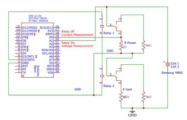
First we will need the current and the voltage values for further data processing. In the circuit shown below, the currentmeasurementisbeencarriedout
RelayOn:OCVMeasurement:ArduinowriterD2toHIGH, which energizes the relay and disconnects the batteries from load. Arduino measures the voltage drop between A1 and GND to determine the OCV of the batteries. R1 andR2create avoltagedividersotheOCVreadingstays withinthe Arduino’s5Vmeasurementbounds.
Fig.no.1a
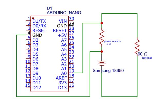
Herebatteryconnectedthetoa1Ωpowerresistoranda 60 Ω test load using a setup similar to the Arduino voltmeter. The Arduino analyses the voltage drop across the power resistor before using Ohm's Law: I=V/R The Arduinothen usesthe Serial monitor tosend thecurrent valuetoPython.
Thisisthecompletecircuitwhichhasarelayandwewill seethefunctioningofthiscircuitindetail
Fig.no.1c
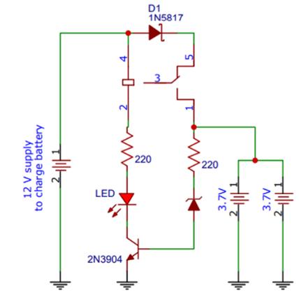
Overchargeprotectionisaveryimportantsteptoensure thatourbatteryperformanceisoptimised.
The circuit given above cuts off the charging half of the circuitbyreversebiasingaZenerdiode.
The batteries charge when the relay is in its non energized state, so to stop charging the cells, the relay mustbecomeenergizedwhenthevoltagedropacrossthe cells reaches 8.4V. To prevent the relay from energizing before then, the ground terminal is connected to the collector of a transistor whose base is connected to a Zenerdiode,aSchottkydiode,andaresistor.
When the batteries are below 8.4V, the voltage drop across the components in the base is insufficient to reverse bias the Zener, which prevents current flow and keeps the transistor in its non conducting state (which actsasanopencircuittotherelay).
Whenthebatteriesreach8.4V,though,basecurrentflows which turns on the transistor, which allows current to flow through the relay, which opens the switch and disconnects the batteries. An LED then turns on to indicatethatthebatteriesarefullycharged.
Fig.no.1b
Relay Off: Current Measurement: The battery is connected to load and discharges through R Power. Arduino measures the voltage drop across R Power by measuringthedropbetweenA0andGND.
International Research Journal of Engineering and Technology (IRJET) e ISSN:2395 0056
Volume: 09 Issue: 06 | June 2022 www.irjet.net p ISSN:2395 0072
which a polynomial function is fitted to get the state ofchargeasafunctionofopencircuitvoltage(OCV).
SOCbasedonCurrentmeasurements
• The 18650 cell is rated at 1.2Ah, so we can easily calculate the total number coulombs the battery can hold.
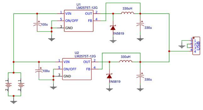
A5Vregulator needsatleast5Vtooperate,andweneed to disconnect the batteries at 2.5V So, since the 5V regulator is the only component the batteries are connected to, the circuit will open if the batteries fall below 5V as the regulator will turn off and produce no output.
• We can then calculate the coulombs used from our current reading. By dividing the coulombs used over our total coulombs, we get the state of charge used. And by subtracting/adding that to the initial state of charge, we end up with the state of charge as a functionoftimeandcurrent.
Total Coulombs Charge of the system = 1.2 Amphr*(60mins/1hr)*(60sec/1min)
The value of the above equation comes out to be 4320 coulombs.
Therefore,thetotalcoloumbsusedwillbegivenby: l*(changeint)
TheSoC(Stateofcharge)usedinpercentageisgivenby, (coulombsused/totalcoulombs)*100
SofinallySoC(t,l)=SoC0 SoCused SoC (l*(changeint/4320))*100
Thisishowthestateofchargeandthestateofhealth ofthelithium ionbatterybackisdetermined.
We trained a model on raspberry pi . the inputs to this model arevoltage,currentandthecharging,discharging rate of the battery. We took this as an input since these aresomeparametersthathasthemaximumeffect onthe batteryperformance.
Finally the output can be observed a display/monitor connected to Raspberry Pi 3. The following parameters line the SOC(State Of Charge), SOH(State Of Health) , Qm (measured maximum capacity in A hr) and EoL are observedastheoutput.
• During data collection, the Arduino collected over 50kdatapointsduringa~21hourdischarge.
• OCV measurements as [measurement number, OCV], normalizedthedatapointstoa0to100%scale,from
Once the value of the SoC is found by using both the methods mentioned above, we use a Kalman Filter model to check which output is the best for our application.Asshown inthe diagram below, firstthe data is collected and then SoC is found as a function of both current and voltage. Then these 2 values are comparedandthebestisthengivenattheoutput.
Fig3:Flowofproposedmodel

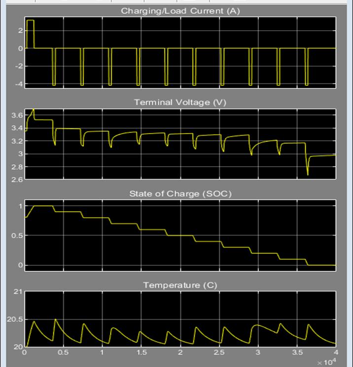
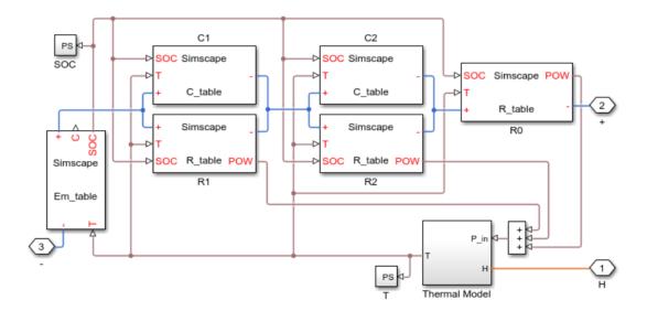
In the OCV method, for simulation Tamb ambient temperature is considered. There are 2 lithium ion cells that are connected to a voltage load in parallel. This is usedtocalculatethebatteryvoltage.Theinputcurrentis also measured as shown in the figure. Finally, these are the simulation results that were obtained. Figure below shows 2RC model taken as a reference from mathworks websiteandchangedfewparametersaspercondition.
Whenthebatteryismanufactured,theSoHofthebattery is 100% but as time goes by and battery is used, the charges in the battery are permanently lost. This affects the battery performance thereby affecting the battery health.
Using the values of the SoC this graph of SoH was obtained.
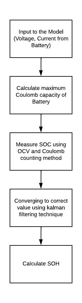
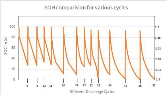
Fig.no.4
To calculate the SoC based on current measurements, mathematical analysis is done which is mentioned in section 2.3. So finally, after both these results are obtained,wepassthemthroughaKalmanFiltermodelto findthebestvalueofSoC.
AftertheSoCisfoundweneedtofindtheStateofHealth. Itisexpressedasapercentageandisdefinedastheratio ofthemaximumbatterychargetotheratedcapacity.
Intheabovegraphwecanclearlyseethatasthenumber of charge discharge cycles increase, the SoH of the batterykeepsonreducing.Oncethisvaluereachesbelow a threshold value battery should no longer be used for anyapplication.
References:
[1]Chatzakis, J., Kalaitzakis, K., Voulgaris, N. C., & Manias, S. N. (2003). Designing a new generalized battery management system. IEEE transactions on IndustrialElectronics,50(5),990 999.
International Research Journal of Engineering and Technology (IRJET) e ISSN:2395 0056
Volume: 09 Issue: 06 | June 2022 www.irjet.net p ISSN:2395 0072
[2]Lelie, M., Braun, T., Knips, M., Nordmann, H., Ringbeck,F.,Zappen,H.,&Sauer,D.U.(2018).Battery managementsystemhardwareconcepts:anoverview. AppliedSciences,8(4),534.
[3]Sen,C.,&Kar,N.C.(2009,September).Batterypack modeling for the analysis of battery management system of a hybrid electric vehicle. In 2009 IEEE Vehicle Power and Propulsion Conference (pp. 207 212).IEEE.
[4]Kumar, B., Khare, N., & Chaturvedi, P. K. (2015, October). Advanced battery management system using MATLAB/Simulink. In 2015 IEEE International Telecommunications Energy Conference (INTELEC) (pp.1 6).IEEE.
[5]Daowd, M., Omar, N., Verbrugge, B., Van Den Bossche, P., & Van Mierlo, J. (2010, November). Battery models parameter estimation based on MATLAB/Simulink®. In Proceedings of the 25th Electric Vehicle Symposium (EVS 25), Shenzhen, China
[6] Huria, Tarun & Jackey, Robyn & Gazzarri, Javier & Saginaw, Michael & Sanghvi, Pravesh. (2013). Battery Model Parameter Estimation Using a Layered Technique: An Example Using a Lithium Iron Phosphate Cell. SAE Technical Papers. 2. 10.4271/2013 01 1547.