International Research Journal of Engineering and Technology (IRJET) e ISSN: 2395 0056

Volume: 09 Issue: 06 | June 2022 www.irjet.net p ISSN: 2395 0072
International Research Journal of Engineering and Technology (IRJET) e ISSN: 2395 0056
Volume: 09 Issue: 06 | June 2022 www.irjet.net p ISSN: 2395 0072
M.A. Morsy 1, Sabry.M. Abdel Aziz 2, *, Khaled Abdelwahed 3, Sabreen A. Abdelwahab 4
1 Professor and Head of Welding and NDT Department, CMRDI, Cairo, Egypt.
2, * Ph.D. Student, Department of Production Technology, Faculty of Technology and Education, Helwan University, Cairo, Egypt.
3 Assistant Professor, Department of Automotive and Tractors Technology, Faculty of Technology and Education, Helwan University, Cairo, Egypt.
4 Associate Professor, Department of Production Technology, Faculty of Technology and Education, Helwan University, Cairo, Egypt. ***
Abstract The existence of tempered martensite in microstructure for armor steel makes the material sensitive to heat input and any thermal process. Thus, welding of this steel can negatively affect the welded joint's properties. In MAG welding process using AWS A5.18 ER70S 6 filler wire, both single V and single bevel joints passed the required tensile strength by the military standard. Moreover, with MIG welding process using AWS A5.9 ER307 filler wire, both joints passed the required tensile strength by the military standard.
Dilution was observed in single V welded joints using both carbon steel and austenitic stainless steel filler metal. The dilution percentage increased in single bevel welded joints more that the obtained in single V joints using both carbon steel and austenitic stainless steel. An increase in cooling rate resulted in a significant increase in joint strength and retainment of base metal hardness value at a shorter distance from the centerline of weld metal (lower than 14 mm). A softening region at the HAZ is formed due to the over tempering of the martensitic structure with a reduction in hardness values. This softening zone is much reduced in width with the increase in its hardness values with the application of cooling and reduction of heat input.
Both single V joint and single bevel joint passed the required absorbed energy in Charpy V notch impact at 40 °C tests whether using carbon steel and austenitic stainless steel filler wire.
Results show that the corrosion rates of weldedjointsare lower than the base metal. It is worthy to mention that the single bevel welded joints give much lower corrosion rates than the base metal and the single bevel welded joints performed using austenitic stainless steel filler wire compared to single bevel welded joint performed using carbon steel filler wire. The results were discussed on the basisofthemechanicalproperties and metallurgical properties of the welded joints.
Key Words: Gasmetalarcwelding(GMAW)process;armor steel welded joints; carbon steel filler metal; austenitic stainless steelfillermetal;weldingparameters;metallurgical properties;mechanicalproperties,corrosionbehaviourtest
Inrecentyears,thereareacceleratedeffortstodeliverarmor technologiesthatcandefeatarmor piercingprojectiles.The selection of steel alloys continues to be competitive for numerousballisticandstructuralapplicationswheretheuse ofultrahighstrengthsteelplatesresultedinthedecreasein theweightofarmorstructurewithgoodballisticproperties [1].
TheArmox500Tbelongstothecategoryofthefine grained, increased strength steels, sometimes called ballistic steels areclassifiedintheAWSstandardsandinmilitarystandards [2]. A combination of the standards is used to classify and identify the metal and methods to process it, which are manufacturedbythequenchingandtemperingprocess[3].
Therefore, these steels have high strength, hardness, and goodtoughnesswhereacquiredthesematerialsstrengthup to 1000 MPa. Most of the higher processed materials that exceedthisrangeareidentifiedinthemilitarystandardMIL St A46100 [4]. The issue with the armor steel is that it reaches very high hardness (around 500 HV) and tensile strength(around 1650 MPa) usingcomplicated processing called thermomechanical controlled processing (TMCP) at hightemperatures,includingquenchedandtempering.This processresultedinthefinegrainsmartensiticstructurewith ultrahighstrengthproperties.Consideringthatthismakesthe steel sensitive to any thermal processing including cutting andweldingprocesses[5,6].
Armorsteelsareusedinmilitaryapplicationsandcounters for banks,doors,andvehiclesforsafelypeopleand money transport,andtanksbodyshielding,andpolicevehicles[7].
An armor has three main roles in order to ensure the protection and integrity of the combat vehicle and its occupants. These three roles are often described as absorption of the penetrator's energy and/or transfer of energytothesupportingstructure;reboundingorchargingof direction of the penetrator away from the vehicle, and deformationofthepenetrator[8].
International Research Journal of Engineering and Technology (IRJET) e ISSN: 2395 0056
Volume: 09 Issue: 06 | June 2022 www.irjet.net p ISSN: 2395 0072
Theweldingcharacteristicsofarmorsteeldependonthegap between plates, types of base materials, filler wire type is used, welding voltage, welding current, wire feed rate, shieldinggas,andtheskilloftheoperator.Therefore,these parameters should be controlled in order to achieve the
Nominal
desiredweldquality[9,10].
composition %
Armox500Tarmorsteel[11]hasgoodweldabilityaccording tothechemicalcompositionbecauseitscarbonequivalentis relativelylow(0.56)[12].
CE=C+Mn/6+(Cr+Mo+V)/5+(Ni+Cu)/15[%] (1)
RequirementsofqualityfortheweldingofMIL A 46100steel aregivenbyMIL STD1185andSD X12140standards.The requirements are divided into three categories: (i) mechanical properties, (ii) weld soundness, and (iii) in serviceperformance[13].
Military standards demonstrate that the ultimate tensile strength of welded joints should exceed 750 MPa to be succeeded using carbon steel filler metal. However, they should exceed a minimum ultimate tensile strength of 550 MPa using austenitic stainless steel filler metal. The retainmentofbasemetalhardnessvaluemustbeachievedat adistanceof16mmmeasuredfromthecentrelineoftheweld bead. The Charpy V notch impact test results of both weld metalandheat affectedzonearealsoimportant[6,13].
Theaimoftheresearchworkistoinvestigatetheweldability ofArmox500Tarmorsteel usingtheGMAWprocess.Two types of filler metals will be applied and also two types of jointconfigurationwillbeused.Theeffectofheatinputand coolingratewillbestudied.Theresultswillbediscussedon the basis of mechanical, metallurgical and corrosion propertiesoftheweldedjoints.
Thissectiondescribestheusedmaterialsandexperimental andtestingmethods.
The base metal was ARMOX 500 T which is a commercial name for armor sheet metals with a dimension of 200*155*10mm.Theheattreatmentincludesaustenitizingat 900ºCthenwaterquenchingandfollowedbytemperingat 200ºC[14].Theobtainedbasemetalhashighhardnessand strength with acceptable toughness. The chemical composition and mechanical properties from the SSAB companyspecificationofbasemetalaspresentedinTables1 and2.
Table 1: ChemicalcompositionsoftheArmox500Tsteel plate,(SSABcompanyspecification),wt.%.
Table -2: TypicalmechanicalpropertiesoftheArmox500T steelplate,(SSABcompanyspecification).
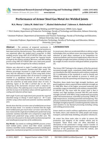
In this investigation, two different weld groove shapes namely single V and single bevel grooves were fabricated usingmachineCNChigh speedwirecutEDM(modelFW2U series Switzerland).Animpermeableholewithadiameterof 1 mm was carried out in the centreline of specimens at a distance of 2.89 mm from the root edge of the groove as showninFig.1.Withadepthof3mmfromthebottomofthe sample, using CNC electrical discharge forming machine (model DM 450 series China). A K type thermocouple is insertedintheholetomeasurethetemperaturechangeinthe heat affectedzone(HAZ).
In this research work, the gas metal arc welding GMAW is applied.Aweldingmachinetype(FroniusVARIOSTAR457 2)isused.Theweldingparametersandconditionsarelisted inTables3,4,andFig.2.Theweldertriestoapplythelowest level filler wires of welding current in order to reduce the deteriorationofHAZmicrostructureasaresultofsoftening [6,15,16].ThegasusedwithER70S 6carbonsteelfillermetal (100%CO2)withaflowrateof12l/mininMAG.However, Argongas100%isusedinthecasewithER307fillermetal with a flow rate of 14 l/min in MIG. The diameter of AWS A5.18ER70S 6wireis0.8mm,howeverthediameterofAWS A5.9ER307wireis1.2mm.Usingausteniticfillermetalisan advantage to decrease the susceptibility to cold cracking [6,16].
2022, IRJET | Impact Factor value: 7.529 | ISO 9001:2008 Certified Journal
International Research Journal of Engineering and Technology (IRJET) e ISSN: 2395 0056
Volume: 09 Issue: 06 | June 2022 www.irjet.net p ISSN: 2395 0072
(kJ/mm) (2)
Hi:Heatinput(kJ/mm)
V:Arcvoltage(Volts)
I:Current(Amperage)
µ:Thermalefficiency(GMAW=0.8)
S:Travelspeed(mm/min)
Samples
2.5
input values (kJ/mm)
2
1.5
1
0.5
2.19 1.39 1.53 1.35 1.04 1.1 1.26 1.1 0
Single V/AWS A 5.18 ER70S-6 Single bevel/ AWS A 5.18 ER70S-6
Single V/AWS A 5.9 ER307 Single bevel/ AWS A 5.9 ER307
Heat input for samples without cooling (kJ/mm)
Heat inputfor samples with cooling (kJ/mm)
Fig-2: Heatinputvaluesofallspecimens.
Table -3: Weldingprocedureparameters.
Number ofpasses Welding current (A)
Arc voltage (V) Wirefeed (m/min) Travel speed (mm/min) Heatinput (kJ/mm)*
SingleV/AWSA5.18ER70S 6 withoutcooling 5 195 27.5 7.5 117.23 2.19
Singlebevel/AWSA5.18ER70S 6 withoutcooling 5 195 27.5 7.5 183.93 1.39
SingleV/AWSA5.9ER307 withoutcooling 4 219 24.5 7.7 167.59 1.53
Singlebevel/AWSA5.9ER307 withoutcooling 4 219 24.5 7.7 190.18 1.35
SingleV/AWSA5.18ER70S 6 withcooling 4 160 25 7.5 183.07 1.04
Singlebevel/AWSA5.18ER70S 6 withcooling 3 160 25 7.5 170.72 1.1
SingleV/AWSA5.9ER307with cooling 3 220 24.5 7.7 200.20 1.26
Singlebevel/AWSA5.9ER307 withcooling 3 220 24.5 7.7 211.21 1.1
Table 4: Weldingprocedureconditions.
Basemetals ARMOX500T
Thicknessofplate 10mm
Weldingprocesstype GMAW
Weldingmachinetype Fronius(VARIOSTAR457 2)
Fillermetaltype AWSA5.18ER70S 6 AWSA5.9ER307 AWSA5.18ER70S 6 AWSA5.9ER307
Jointtypeandangle SingleV(60º)andSinglebevel(30º)
Fillerwirediameter(mm) 0.8 1.2 0.8 1.2
Gas(%) 100%CO2 100%Argon 100%CO2 100%Argon
Gasflowratel/min 12 14 12 14
Weldingmethods Continuous Notcontinuous
Coolingmethod Withoutcooling(leftatambient temperatureaftercompletionofthewhole welding) Withusingcompressedair(6bar)inthe coolingaftereachpassupto100ºC
International Research Journal of Engineering and Technology (IRJET) e ISSN: 2395 0056
Volume: 09 Issue: 06 | June 2022 www.irjet.net p ISSN: 2395 0072
TwofillermetalsareusedwiththeGMAWprocessoneisa carbon steel AWS A 5.18 ER 70S 6 and the other is an austenitictypeAWSA5.9ER307.Theselectionwasbasedon theresultsobtainedinpreviousliteratureby[6,15,16,17]and filler metal manufacturers' specifications [18,19,20] and requirementsfortheweldingofarmorsteelaccordingtoMIL STD1185standards[21].Usingausteniticfillermetalisan advantagetodecreasethesusceptibilitytocoldcracking[15, 17]. The welder tries to apply the lowest level filler wire weldingcurrentinordertoreducethedeteriorationofHAZ microstructureasaresultofsoftening[6,15,16,22,23].
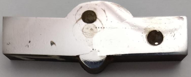
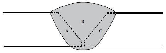
An optical emission spectrometry equipment is used to determinethechemicalcompositionsofbasemetalandweld metals.Thecross sections werepreparedfor metallurgical observations.Thisincludesgrindingbysandpapersfrom100 to 1000 mesh and finally polished using alumina paste. Etching using a 2 % Nital solution was used to reveal the martensiticstructure.However,10%oxalicacidwasusedto revealtheausteniticstructure.Microstructurecharacteristics of weld metal (WM) at various locations, base metal (BM), andheat affectedzone(HAZ)regionswereobservedbyan optical microscope (OLYMPUS MODEL PMG3 F3). A stereoscope is used to show the macrostructure of welded joints. The dilution percentage was calculated using the equation(3)illustratedinFig.3.[24].
Dilution(%)=A+B/A+B+C*100 (3)
and HAZ were performed according to ASTM E23 12 c standard[27].Fivereadingsweretakenineachlocation.
Thecorrosionbehaviourofbasemetalandweldedjointswas investigated using electrochemical corrosion testing apparatus(AutolabNOVA2.1.5)in3.5wt%NaClsolutionat roomtemperature[28].Sampleswerecorrosiontestedusing potentiodynamicpolarizationandelectrochemicalimpedance (EIS) techniques. Samples were polished up to 1200 grit finish, ultrasonically cleaned and rinsed with ethanol, and finallydried.Aconventionalthree electrodecellinasingle compartment cylindricalglasscellwasusedwithaPtcounter electrode.Allthepotentialswererecordedwithrespecttoa saturated calomel electrode (SCE) reference electrode at 25oC.Sodiumchloridemediumwaspreparedfromanalytical grade chemicals and bi distilled water. The potential was scanned starting from 0.3 V below Ecorr in the positive direction (~ 1 V above Ecorr). Corrosion parameters; corrosion potential (Ecorr), Corrosion current (Icorr), and corrosion rate (CR) were deduced from the polarization curvesusingAutoLabsoftwareasshowninFig.4.
Hardness distributions have been carried out by using the Vickers hardness testing machine model (DVK 2 Tokyo Japan) was employed with a 20 kg load for 70 seconds to measurethehardnessdistributionattheweldedjoints.The hardnessprofilethroughweldmetal,HAZ,andthebasemetal willbedeterminedwithapitchofmeasurementpositionof1 mm. The test has been carried out according to ASTM standards[25].Transversetensiletestshavebeencarriedout using a tensile machine model (Universal Testing Machine WDW 300China).Thetesthasbeencarriedoutaccordingto ASTM A370 12 [26], using two specimens. Charpy V notch impacttestwasdoneusingaCharpyVnotchimpacttesting machineusingalow temperaturechamberat 40°Candalso atroomtemperature.Charpyimpacttestsintheweldmetal
3.1.
The chemical analysis of base metal from SSAB company specificationandactualanalysisforbasemetalispresented inTable5.ThemechanicalpropertiesareshowninTable6.
The chemical composition of all weld metals is shown in Table7.
International Research Journal of Engineering and Technology (IRJET) e ISSN: 2395 0056
Volume: 09 Issue: 06 | June 2022 www.irjet.net p ISSN: 2395 0072
Table -5: ChemicalcompositionsoftheArmox500Tsteelplate,wt.%
1.2 max Yield
Hardness(HV)
0.010 max Tensile
0.7 max
0.005 max
0.67 max Bal Actualanalysis 0.154 0.2 0.88 0.009 0.003 0.5 0.89 0.36 0.001 0.56 Bal
Table 6: ThemechanicalpropertiesoftheArmox500Tsteelplate.
strength (MPa)
Thecoolingrateisdeterminedusingtwotemperatureranges. Onebetween800°Cto500°Candtheotherrangebetween 600°Cand200°C[29].
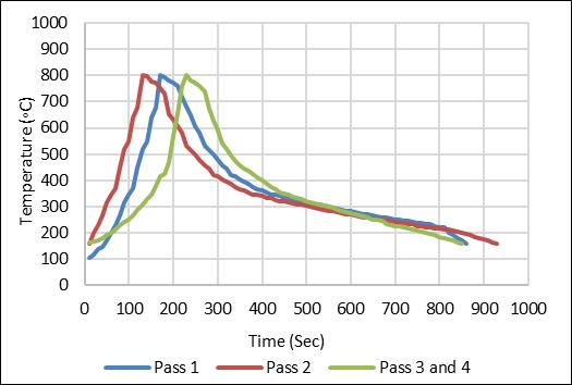
Figure5showsthecoolingrateofweldedsampleswithout using compressed air after completion of welding. The cooling time (t 8/5) of the first pass is 30 seconds, the coolingrate(t8/5)is10°C/sec.Thecoolingrate(t8/5)of thesecond,thethird,andthefourthpassesis11°C/sec.The coolingtime(t6/2)ofthefirstpassis230secondsandthe meancoolingrate(t6/2)is1.73°C/sec.Thecoolingrate(t 6/2) of the second, the third, and the fourth passes is 1.63 °C/sec.
Temperature (ºC)
1.0 max Time
strength (MPa) Elongation(%) CharpyVnotchimpacttestspecimen(10*10*55mm)at 40ºC 450 1250 1650 8.9 34(J) Elements C Si Mn P S Cr Ni Mo V Fe AWSA5.9ER307 0.09 0.9 7 0.001 0.002 19 8.5 0.13 0.03 Bal AWSA5.18ER70S 6 0.07 0.8 1.45 0.002 0.003 0.025 0.05 0.002 0.012 Bal
Table 7: Thechemicalcompositionofallweldmetals,wt.%.
1.8 max Pass
(Sec)
International Research Journal of Engineering and Technology (IRJET) e ISSN: 2395 0056
Volume: 09 Issue: 06 | June 2022 www.irjet.net p ISSN: 2395 0072
Figure 7 shows the cooling rate at the HAZ with the applicationofcompressedairimmediatelyaftercompletion ofwelding.Thecoolingtime(t6/2)ofthefirstpassis110 seconds,thesecondpassis160seconds,thethirdpassis170 seconds. The cooling rate (t 6/2) of the first pass is 3.64 °C/sec, the cooling rate (t 6/2) of the second pass is 2.5 °C/sec,andthecoolingrate(t6/2)ofthethirdpassis2.35 °C/sec.
0 100 200 300 400 500 600 700 800 900 1000 0 100 200 300 400 500 600 700 800 900 1000
Figure 9 shows the cooling rate at the HAZ with the applicationofcompressedairimmediatelyaftercompletion ofwelding.Thecoolingtime(t6/2)ofthefirstpassis150 seconds,thesecondpassis120seconds,thethirdpassis120 seconds. The cooling rate (t 6/2) of the first pass is 2.66 °C/sec, the cooling rate (t 6/2) of the second pass is 3.33 °C/sec,andthecoolingrate(t6/2)ofthethirdpassis3.33 °C/sec.
Temperature (ºC) Time (Sec) Pass 1 Pass 2 Pass 3
0 100 200 300 400 500 600 700 800 900 1000 0 100 200 300 400 500 600 700 800 900 1000
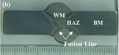
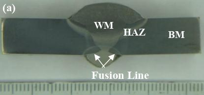
Fig -7: Temperaturecycleforsinglebevel/ER70S-6/MAG withcooling.
Figure 8 shows the cooling rate at the HAZ with the applicationofcompressedairimmediatelyaftercompletion ofwelding.Thecoolingtime(t8/5)ofthefirstpassis70 seconds,thecoolingrate(t8/5)is4.29°C/sec.Thesecond passis70seconds,thecoolingrate(t8/5)is4.29°C/sec. Andthecoolingtime(t6/2)ofthefirstpassis160seconds, thecoolingrate(t6/2)is2.5°C/sec.Thecoolingrate (t 6/2) of the second, and the third passes is 2.5 °C/sec, and 3.64°C/sec,respectively
Temperature (ºC) Time(Sec) Pass 1 Pass 2 Pass 3 0 100 200 300 400 500 600 700 800 900 1000 0 100 200 300 400 500 600 700 800 900 1000
Temperature (ºC) Time(Sec) Pass 1 Pass 2 Pass 3
Fig -8: TemperaturecycleforsingleV/ER 307/MIG with cooling.
Fig -9: Temperaturecycleforsinglebevel/ER307/MIGwith cooling.
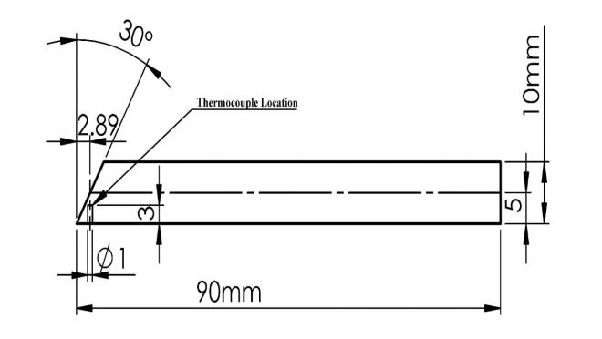
ThemacrostructuresofalltheweldedjointsareshowninFig. 10. As can be seen from the mentioned Figures, all of the samples (except for sample c) have a significant reinforcement due to the final two layers this occurs as a consequence of the reduction amperage and increases in weldingspeed.Theweldedjointsareallhomogenouswithout theoccurrenceofporesorinclusionsorcracks.Penetrationof allweldpassesissufficientandnolackoffusionwasnoticed.
International Research Journal of Engineering and Technology (IRJET)
e ISSN: 2395 0056
Volume: 09 Issue: 06 | June 2022 www.irjet.net p ISSN: 2395 0072
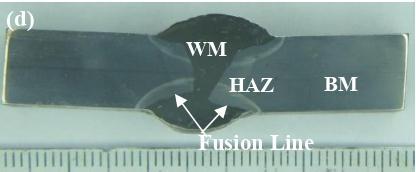
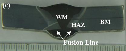
Figure 12.a shows the microstructure of weld metal WM using carbon steel wire for a single V joint groove, it is a columnar structure composed of polygonal ferrite and acicularferrite.Figure.12.bshowsthemicrostructureofthe weldmetalandheat affectedzone.Heat affectedzoneshows the over tempering of martensitic structure. Figure. 12.c showsthemicrostructureoftheover temperedzoneconsists of martensitic and over tempered martensite structures. However, Figure 12.d shows the over tempered (softening zone)whichisexposedtoatemperaturelowerthanAC1
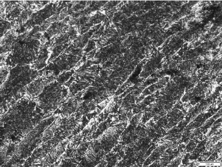
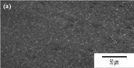
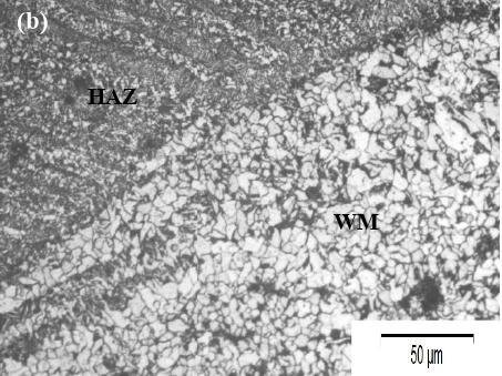
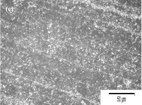
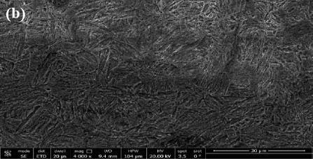
Fig 10: Macrographicofweldedsamplesa)singleV/ER70S 6/ MAG with cooling b) single bevel/ ER70S 6/ MAG with coolingc)singleV/ER307/MIGwithcoolingd)singlebevel/ ER307/MIGwithcooling.
Figure11.ashowsthemicrostructureofthebasemetal.Itis tempered martensite with retained austenite. Figure 11.b showstheSEMobservationofbasemetalwhichisalathof martensite structure that occurs due to the low tempering temperatureoftheheat treatmentprocess.
Fig -11: Themicrostructureofthebasemetal(ARMOX500T) armorsteela)opticalmicroscopeb)SEMobservation.
Fig 12: MicrostructureofsingleVweldedjointusingAWSA 5.18 ER70S 6 filler metal a) weld metal b) weld metal and HAZ c) over tempered zone composed of martensitic and over tempered martensite d) over tempered (softening zone).
Figure. 13.a shows the microstructure of the weld metal regioninthejointweldedusingcarbonsteelfillerwirewith singlebeveljointgroovepreparation.Itiscolumnargrainand ferriteandpearlite.Figure.13.bshowsthecellularstructure intheweldmetalregionandthisoccursduetotheannealing process generated by multiple passes of welding in this region.Figure.13.cshowsthemicrostructureofheataffected zone(HAZ).Itisamartensiticstructureregionthatreaches the austenitic and cooled rapidly to form a martensitic structure.However,Figure.13.dshowstheover tempering (softeningzone)thatreachesoverthanAC1temperaturethat caseover temperingandsofteningofmicrostructure.
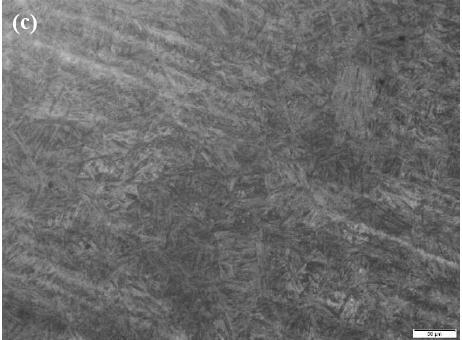
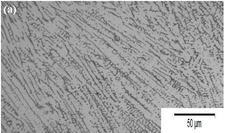
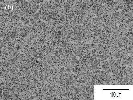
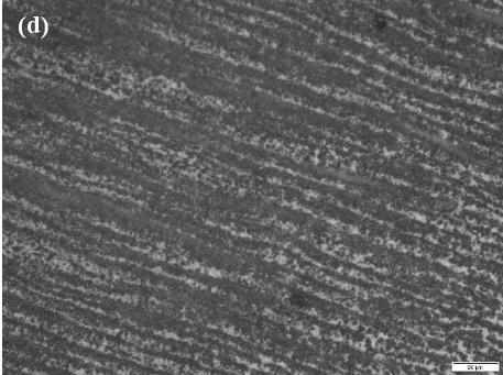
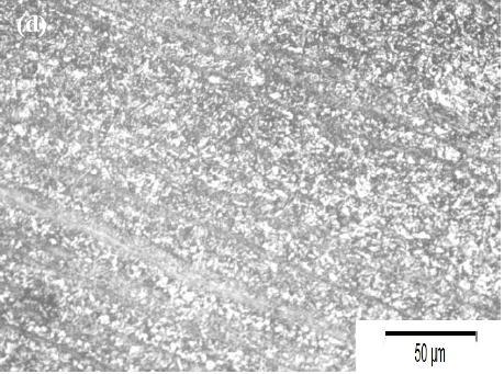
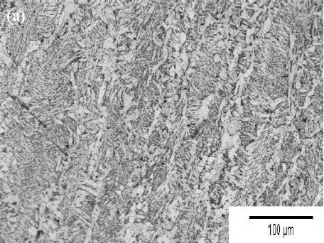
Fig 13: Microstructure of single bevel welded joint using AWS A 5.18 ER70S 6 filler metal a) weld metal b) cellular structurezoneinweldmetalc)martensiticstructureinHAZ zoned)over tempering(softeningzone).
Figure.14.aand14.bshowsthemicrostructureoftheweld metal using austenitic stainless steel wire single V joint groove,itistheausteniticcolumnarstructure.andindicates thattheweldcapreflectedlowdilutionatthecap.However, Figure.14.cshowsthemicrostructureoftheHAZforasingle bevel joint groove, it is the grain coarsening martensitic structure,andthisindicatesthatthisregionreachedaboutto temperature 1250 ºC which caused grain coarsening, Figure.14. d shows the existence of grain refinement martensite structure, and this indicated that this region reachedatemperatureofabout900ºC.Figure.14.eshows the existence of over tempering microstructure in the HAZ zoneasindicatedbytheriseoftheseregions'temperatureto a high value lower than the austenitizing temperature yet overtemperingtemperature
International Research Journal of Engineering and Technology (IRJET) e ISSN: 2395 0056
Volume: 09 Issue: 06 | June 2022 www.irjet.net p ISSN: 2395 0072
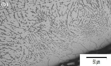
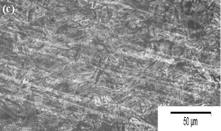
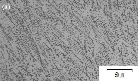
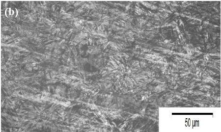
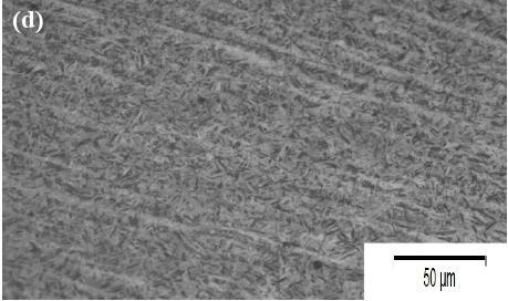
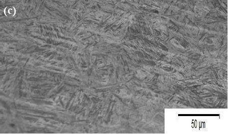
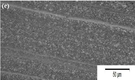
Figure.15.ashowthemicrostructureoftheweldmetalusing austeniticstainless steelwiresinglebevel jointgroove,itis the austenitic columnar structure. Figure.15. b shows the martensiticstructureattheedgeofthejointintheweldmetal of the root zone (close to HAZ) and this reflects the high dilutionpercentageoftheweldmetalarmorsteelbasemetal (seesection3.7).Figure.15.cshowsthemicrostructureofthe HAZforasinglebevel jointgroove,itisthegraincoarsening martensitic structure, and this indicates that this region reached about to temperature1250ºCwhichcausedgrain coarsening, Figure.15. d shows the existence of grain refinementmartensitestructure,andthisindicatedthatthis regionreachedatemperatureofabout900ºC.Figure.15.e showstheexistenceofovertemperingzonemicrostructure (softened zone) and this indicates that these regions were exposed to a temperature that caused over tempering of microstructure
Fig 14: MicrostructureofsingleVweldedjointusingAWSA 5.9 ER307 filler metal a) and b) weld metal c) the microstructureofHAZgraincoarseningmartensiticstructure d)grainrefinementmartensitestructuree)over tempering (softeningzone).
International Research Journal of Engineering and Technology (IRJET) e ISSN: 2395 0056
Volume: 09 Issue: 06 | June 2022 www.irjet.net p ISSN: 2395 0072
Figure. 17 shows the hardness distribution of the joint weldedusingAWSA5.18ER70S 6fillerwireandapplyinga single bevel groove joint. It can be concluded that the applicationofasinglebevelgroovewithcoolingresultedina retainmentofthebasemetalhardnessvalueatadistanceof 13 mm (480 HV) from the weld metal center. The higher hardness values could be attributed to the existence of martensitic structure in this region as a result of higher coolingrate
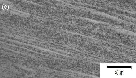
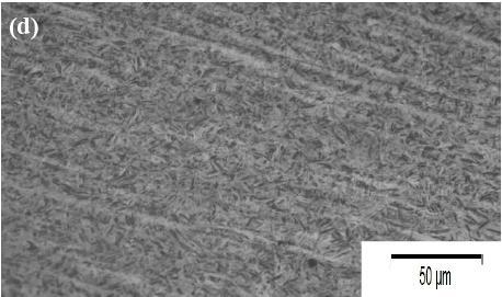
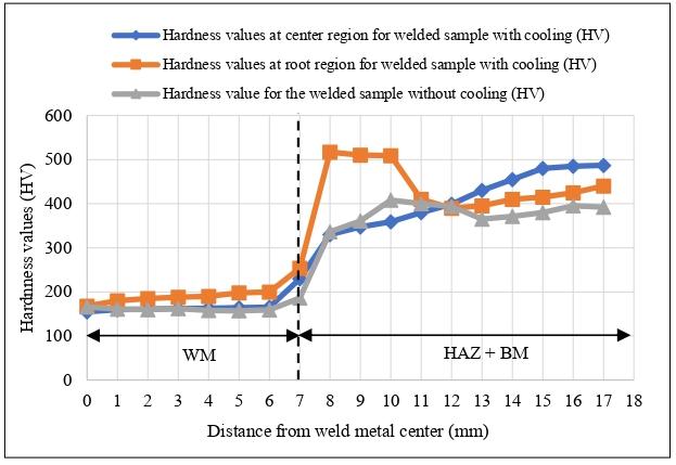
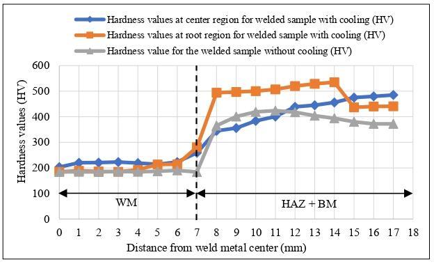
Fig 15: Microstructure of single bevel welded joint using AWS A 5.9 ER307 filler metal a) weld metal b) martensite structure in HAZ zone c) the microstructure of HAZ grain coarsening martensitic structure d) grain refinement martensitestructuree)over tempering(softeningzone).
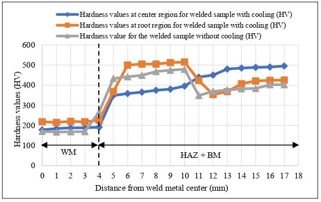
Figure. 16 shows the hardness distribution of the joint weldedusingAWSA5.18ER70S 6fillerwireandapplyinga singleV groovejoint.Thehardnessvaluesabruptlyincreased fromtheweldmetalinthegraincoarseningzoneoftheHAZ. Thehardnessthendecreasestoalowervaluethanthatofthe basemetal.Thiscouldbeattributedtotheovertemperingof thiszone.Thehardnessagainincreasestoreachtonearthat of the base metal. Application of cooling resulted in the significantretainmentofbasemetalhardnessatadistanceof 14mm(455HV)fromthecentrelineofweldmetal.Thehigh weld metal hardness at the root could be attributed to the higherdilutionofweldmetalfrombasemetal.
Fig -17: Hardnessdistributioninthespecimenweldedusing AWSA5.18ER70S-6/MAGandapplyingsinglebeveljoint.
Figure. 18 shows the hardness distribution of the joint welded using AWS A5.9 ER 307 filler wire and applying a singleVgroovejoint.Hardnessincreasesfromweldmetalto a high value at the HAZ. Retainment of the base metal hardness occurred at a distance of 14 mm from the weld metal center (450 HV) with the application of cooling. However, the retainment of base metal hardness does not occuratadistanceof16mmwithoutcoolingapplication
Fig -16: Hardnessdistributioninthespecimenweldedusing AWSA5.18ER70S-6/MAGandapplyingsingleVjoint.
Fig -18: Hardnessdistributioninthespecimenweldedusing AWSA5.9ER307/MIGandapplyingsingleVjoint.
International Research Journal of Engineering and Technology (IRJET) e ISSN: 2395 0056
Volume: 09 Issue: 06 | June 2022 www.irjet.net p ISSN: 2395 0072
Figure. 19 shows the hardness distribution of the joint welded using AWS A5.9 ER 307 filler wire and applying a singlebevelgroovejoint.Hardnesskeptincreasinggradually with a retainment of the base metal hardness value at a distanceof13mm(450HV)fromtheweldmetalcenter.
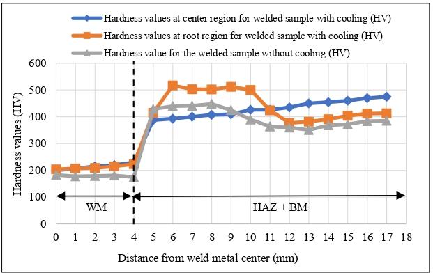
Figure 21 shows the Schaeffler diagram indicating two different dilution levels using a single V groove (18 % dilution) and single bevel groove (56 % dilution) when applying AWS, A 5.9 ER 307 as a filler metal. The Figure indicatingthatthemicrostructureoftheweldmetalismainly austeniteanddeltaferriteusingsingleV(18%dilution).On the other hand, the microstructure of the weld metal is mainly martensite and austenite using single bevel groove (56%dilution).Thiswasconfirmedwiththeobservationof microstructuresshowninFig.14and15.
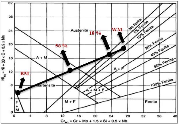
Fig -19: Hardnessdistributioninthespecimenweldedusing AWSA5.9ER307/MIGandapplyingsinglebeveljoint.
Figure20showsthedilutionspercentageofthesingleVand bevel groove joints with the GMAW welding process using AWSA5.18ER70S 6andAWSA5.9ER307fillerwires.The dilution in the single V joint was less than the single bevel joint using AWS A5.18 ER70S 6 filler wire. The dilution process affects greatly the mechanical and metallurgical propertiesofweldmetalthatdeviatefromthepurefillerwire properties. This can be observed in the tensile strength of weldedjointasshowninTable.8asmentionedinsection3.8. Also,thedilutionaffectsthemicrostructureofweldmetalas shown in Fig.15. b (see section 3.5). The existence of martensite structure greatly affects the improvement of tensilestrength.
Fig -21: Schaefflerdiagramindicatingthelocationsofpure weldmetal(WM)basemetal(BM)andthecompositionsof weldmetalwithdifferentjoints(differentdilutions).
Table 8 and Fig. 22 show the ultimate tensile strength of weldedjointsusingcarbonsteelandausteniticstainless steel fillermetalsusingsingleVandsinglebevelgroovejoints.In thisTable,theoreticalvaluesoftensilestrengthforallfiller metals(pure)usedhavebeenincluded[13].Fromthedatain Table 8 and Fig.22, it was found that in all cases the requirements for qualification are fulfilled. An increase in ultimatetensilestrengthofweldedmetalwithrespecttothe fillermetalwasalsofound.Thiscouldbeasaconsequenceof anincreaseindilutionpercentage.Thefracturesarelocated intheweldmetalinallspecimenswhetherusingcarbonsteel andausteniticstainless steelfillerwires.
Fig -20: Effectofjointtypes,heatinput,andfillermetalson dilution.
Table 9 and Fig.23 show the Charpy V notch impact tests resultsoftestsconductedatroomtemperatureandat 40ºC in the weld metal region. In addition, the Charpy V notch impacttestwasconductedatroomtemperatureandat 40 ºC in the heat affected zone region. An increase in impact energy joint welded using AWS A 5.9 ER 307 filler metal showsasignificantincreaseinimpactresistancesshownin Fig.23andTable9.Allweldmetalnotchedimpactspecimens were fractured at weld metals. However, all HAZ notched impactspecimenswerefracturedatHAZ.
International Research Journal of Engineering and Technology (IRJET) e ISSN: 2395 0056
Volume: 09 Issue: 06 | June 2022 www.irjet.net p ISSN: 2395 0072
Table -8: Tensilestrengthpropertiesofweldedjoints
Jointtypeandfillermetalclassification
Tensilestrengthof sampleswithoutcooling, MPa
Tensilestrengthof sampleswithcooling, MPa Fracturelocation
Strengthofallweld metal(pure)used, MPa, [6,20]
SingleV/AWSA5.18ER70S 6 719.92 845.5 WM 540
Singlebevel/AWSA5.18ER70S 6 815.03 890.5 WM 540
SingleV/AWSA5.9ER307 824.31 867.14 WM 620 Singlebevel/AWSA5.9ER307 834 898.5 WM 620
Fig 22: Tensile strength properties values of weldedjoints
Tensile strength values (MPa)
719.92 815.03 824.31 834 845.5 890.5 867.14 898.5 540 540 620 620 0 100 200 300 400 500 600 700 800 900 1000 SingleV/MAG / ER70S-6 Singlebevel/ MAG /ER70S-6 SingleV/MIG / ER307 Single bevel/ MIG/ ER307
Ultimatetensile strength for samples without cooling,(MPa)
Ultimatetensile strength for samples with cooling, (MPa) Strength ofall weld metal(pure)used, (MPa)
Table 9: Impactenergypropertiesvaluesofweldedjoints
Jointtypeandfillermetal classification
CharpyVnotch(CVN)resultsin(J) WMatRT, without cooling
WMat 40°C, without cooling
WMatRT, with cooling
WMat 40°C, with cooling
HAZat RT,with cooling
HAZat 40°C, with cooling
CVNofthe usedfiller metalatRT, [20]
CVNoftheused fillermetal at 40°C,[20]
SingleV/AWSA5.18ER70S 6 105 41 132 61 90 78 120 50
Singlebevel/AWSA5.18ER70S 6 75 32 84 51 85 73 120 50
SingleV/AWSA5.9ER307 85 51 95 63 140 130 120 110 Singlebevel/AWSA5.9ER307 43 61 134 65 133 126 120 110
Impact energy results in WM region at (- 40 °C), with cooling (J)
MAG ER70S-6 singleV MAG ER70S-6 singlebevel MIGER307 single V MIGER307 single bevel Fig -23:
Impact energy results in HAZ region at (- 40 °C), with cooling (J)
International Research Journal of Engineering and Technology (IRJET)
e ISSN: 2395 0056
Volume: 09 Issue: 06 | June 2022 www.irjet.net p ISSN: 2395 0072
Table 10 and Figure 24 show the potentiodynamic polarizationcurvesaswellasthecorrosionparametersofthe basemetalandtheweldingregions.Thebasemetalshavea tempered martensite microstructure. The GMAW process used welding filler wires of either carbon steel AWS A5.18 ER70S 6 with ferrite pearlite microstructure or austenitic stainless steel with austenite columnar structure microstructure.TheGMAWprocessappliedbothsingleVand singlebevelgroovejoints. Resultsshowthatthecorrosion rates of welded joints are lower than the base metal. It is worthy to mention that the single bevel welded joints give much lower corrosion rates than the base metal and the single bevel welded joints performed using austenitic stainless steel filler wire compared to single bevel welded joint performed using carbon steel filler wire. Potentiodynamic polarization curves indicate the shift of Ecorrinthenoble(positive)directioninthecaseofwelded joints performedusingausteniticstainless steel filler wire. However,thenobleshiftofEcorrismuchhigherinthecaseof asinglebevelweldedjoint. Itisalsonoticedthatthepositive shiftofEcorrisaccompaniedbyareductioninthemeasured anodiccurrent.
Table -10: Comparisonbetweencorrosionparametersofthe basemetalregionandallweldedjoints
Samples Ecorr (V) Icorr (A/Cm2) Corrosion rate mm/year
Base metal 0.598 7.97x10 6 0.0598
Single V/AWSA5.18 ER70S 6 with cooling 0.640 6.73 x10 6 0.0515
Single bevel/AWSA5.18 ER70S 6 with cooling 0.646 2.00 x10 6 0.0150
Single V/AWSA5.9 ER307 with cooling 0.571 6.66 x10 6 0.0495
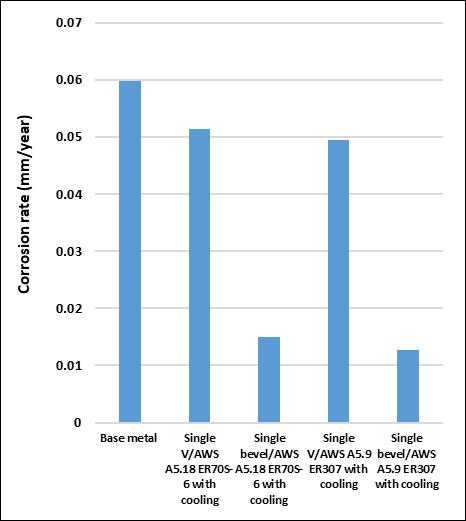
Fig -24: Comparison between corrosion rate of base metal andallweldedjoints.
3.10.1.
Thereducedcorrosionresistanceofthebasemetalcompared to the welding joints may be attributed to its tempered martensitemicrostructurewithalathshapemorphologyand a high density of dislocations [30]. On the other hand, the ferrite pearlite microstructure of the welding joints performed using carbon steel filler wire makes it less susceptible towards corrosion attack. The austenitic microstructure of the welding joints performed using stainless steel filler wire makes it the highest corrosion resistanceamongstthetestedmaterials.Theenhancementof the corrosion resistance of the austenitic stainless is attributed to its high content of Cr, and Ni resulting in the formation of a passive film that protects the metal from corrosion[31].ThepresenceofMointheausteniticstainless furtherimprovesitscorrosionresistancebytheimprovement of the passive film quality and treats defects and imperfectionsthatmayexistinthefilm[30,31].
BaseMetal
SV/AWSA5.18ER70S-6 SB/AWSA5.18ER70S-6 SV/AWSA5.9ER307 SB/AWSA5.9ER307
Single bevel/AWSA5.9 ER307 with cooling 0.316 1.32 x10 6 0.0127 LogCurrent/Acm-2
ThedesignedweldingprocedureusingtheGMAWwithAWS A5.18ER70S 6andAWSA5.9ER307fillermetalwerefound tobeasuitableoptionforweldingarmorsteel,basedonthe resultsobtainedinmechanicalandmetallurgicalobservation ofweldedjoints.Thefollowingresultscanbeconcluded.
1.InMAGweldingprocessusingAWSA5.18ER70S 6filler wire,bothsingleVandsinglebeveljointspassedtherequired tensilestrengthbythemilitarystandard.Moreover,withMIG weldingprocessusingAWSA5.9ER307fillerwire,bothjoints passedtherequiredtensilestrengthbythemilitarystandard.
2.DilutionwasobservedinsingleVweldedjointsusingboth carbon steel and austenitic stainless steel filler metal. The dilution percentage increasedinsingle bevel weldedjoints usingbothcarbonsteelandausteniticstainlesssteel.
International Research Journal of Engineering and Technology (IRJET) e ISSN: 2395 0056
Volume: 09 Issue: 06 | June 2022 www.irjet.net p ISSN: 2395 0072
3.Theultimatetensilestrengthofweldedjointsusingasingle bevel is slightly higher than that of joints welded using a singleV groove.Thiscould beattributedto theincreasein dilutionpercentagewiththesinglebeveljoints.
4.Anincreaseincoolingrateisaccomplishedbyapplyinga compressedair(6bar)coolingimmediatelyaftercompletion of each pass until the temperature falls to 100 °C. Also, a reduction in heat input was performed by a decrease in weldingcurrent.Thisresultedinasignificantincreaseinjoint strength and retainment of base metal hardness value at a shorter distance from the centreline of weld metal (lower than14mm).
5.AsofteningregionattheHAZisformedduetotheover tempering of the martensitic structure with a reduction in hardness values. This softening zone is much reduced in width with the increase in its hardness values with the applicationofcoolingandreductionofheatinput.
6. Both single V joint and single bevel joint passed the requiredabsorbedenergyinCharpyVnotchimpactat 40°C testswhetherusingcarbonsteelandausteniticstainless steel fillerwire.
7.Resultsshowthatthecorrosionratesofweldedjointsare lowerthanthebasemetal. Itisworthytomentionthatthe singlebevelweldedjointsgivemuchlowercorrosionrates than the base metal and the single bevel welded joints performed using austenitic stainless steel filler wire compared to single bevel welded joint performed using carbonsteelfillerwire.Potentiodynamicpolarizationcurves indicatetheshiftofEcorrinthenoble(positive)directionin the case of welded joints performed using austenitic stainless steelfillerwire. However,thenobleshiftofEcorris muchhigherinthecaseofasinglebevelweldedjoint. Itis alsonoticedthatthepositiveshiftofEcorrisaccompaniedby areductioninthemeasuredanodiccurrent.
CVN Charpy V Notch Impact Test
[1]Scazzosi,R.;Giglio,M.;Manes,A.(2021),“Experimental andNumericalInvestigationonthePerforationResistanceof Double LayeredMetalShieldsUnderHigh VelocityImpactof Soft CoreProjectiles”,Eng.Struct.,228,111467.
[2] Lazić Vukić, Arsić Dušan, Nikolić Ružica, Uhričik Milan, Hadzima,Branislav.(2019),“InfluenceoftheWeldingJoint typeonSafetyPropertiesoftheArmorSteelARMOX500T”, MaterialsScience.SystemSafety:Human TechnicalFacility Environment.volume1,issue1,pp.753 759.
[3]IgorBarényi,JozefMajerík,JánBezecný,MichalKrbaťa, JosefSedlák,AlešJaroš.(2019),“MaterialandTechnological Aspects while Processing of Selected Ultra High Strength Steel”,ManufacturingTechnology,ISSN1213 2489,Vol.19, No.2PP184 189.
[4]BalakrishnanM.,BalasubramanianV.,ReddyG.M.(2013), “TEMPEffectofHard FacedInterlayerThicknessonBallistic PerformanceofArmourSteelWelds”,MaterialsandDesign, 44(2013)59 68.
[5] Lazić, V., Arsić, D., Nikolić, R. R., Djordjević, D., Prokić Cvetković, R., Popović, O. (2017), “Application of the High StrengthSteelHARDOX450forManufacturingofAssemblies intheMilitaryIndustry”,KeyEngineeringMaterials,755,96 105.
[6] Morsy Amin Morsy, Rashad El Hebeary. (2019), ‘WeldabilityofArmorSteel’’,72ndIIWAnnualAssemblyand Internationalconference,7 12July2019,PP2 10.
[7] Arkadiusz Popławski, Piotr Kędzierski, Andrzej Morka. (2020),“IdentificationofArmox500TSteelFailureProperties intheModellingofPerforationProblems”,Materials&Design, ELSEVIER,Volume190,May2020,108536.
[8]IvicaGarašić,MajaJurica,DarioIljkić,AnteBarišić.(2019), “DeterminationofBallisticPropertiesonARMOX500TSteel WeldedJoint”,EngineeringReview,Vol.39,Issue2,186 196.
[9] Saiprasad. P.V, Surendra. I.V, Narayan. K. L, Narasimha Rao.L.N.V.(2014),“EvaluationofPercentageofDilution in GasMetalARCWelding”,ISSN:2249 5762,IJRMETVol.4,PP 131 134.
[10]Grujicic.M,Ramaswami.S,Snipes.J.S,Yavari.R,Yen.C.F, Cheeseman B.A. (2015), “Optimization of Gas Metal Arc WeldingGMAWProcessforMaximumBallisticLimitinMIL A46100SteelWeldedAll MetalArmor”,JournalofMaterials Engineering and Performance volume 24, pages229 244 (2015).
[11]Arsić,D.,Nikolić,R.,Lazić,V.,Hadzima,B.,Aleksandrović, S.,Djordjević,M.(2014),“WeldabilityEstimatesofSomeHigh Strength Steels”, 42. International Conference "Zvaranie 2014",TatranskáLomnica,Slovakia,11 21.
[12]TekinÖzdemir.(2020),“Mechanical&Microstructural AnalysisofArmorSteelWeldedJoints”,InternationalJournal ofEngineeringResearchandDevelopment,UMAGD12,166 175.
[13] Robledo D.M, Gomez J.A.S, Barrada J.E.G. (2011), “Development of a Welding Procedure for MIL A 46100 ArmorSteelJointsUsingGasMetalArcWelding”,78,168,65 71.
[14] SSAB OXELOSUND SWEDEN: The steel book. Sweden, 2008.[online10.6.2012].Available:http://www.ssab.com.
[15] Magudeeswarana V.G, Balasubramanianb G, MadhusudanReddy.(2018)Metallurgicalcharacteristicsof armour steel welded joints used for combat vehicle
International Research Journal of Engineering and Technology (IRJET) e ISSN: 2395 0056
Volume: 09 Issue: 06 | June 2022 www.irjet.net p ISSN: 2395 0072
construction.DefenseTechnologyVolume14,Issue5,Pages 590 606.
[16] Ambuj Saxena, Shashi Prakash Dwivedi, Shubham Sharma, Vishal Shankar Srivastava. (2021) A comparative numericalanalysisontheeffectofweldingconsumableson theballisticresistanceofSMAWjointsofarmorsteel.Appl. Sci.2021,11,3629.
[17]KrishnaMurthy.N,JanakiRam.G.D,Murty.B.S,Reddy. G.M,Rao.T.J.P.(2014)Carbide freebainiticweldmetal:A new concept in welding of armor steels. Metallurgical and MaterialsTransactionsBvolume45,pages2327 2337.
[18] SSAB Armox welding recommendations., SSAB OxelOsundAB:OxelOsund,Sweden(2005).
[19]Voestalpine(2019)Böhlerofweldingproductcatalogue. P30 P360.
[20]ESAB.(2016)Weldingfillermetal,DATABOOK,2016.
[21]DoDEFENSE,MILSTD1185.(1979)MilitaryStandard. Welding, high hardness armor, DoD, DEPARTMENT OF DEFENSE.
[22]ArkadiuszPopławski,PiotrKędzierski,AndrzejMorka. (2020)Identificationofarmox500Tsteelfailureproperties inthemodellingofperforationproblems.Materials&Design, ELSEVIER,Volume190,May2020,108536.
[23] DAVID MAZUERA ROBLEDO, JOHN ALBERTO SUÁREZ GÓMEZ, JORGE ENRIQUE GIRALDO BARRADA. (2011) DevelopmentofAweldingprocedureforMILA46100armor steeljointsusinggasmetal arcwelding.Dyna,año78, Nro. 168,pp.65 71.Medellín,Agosto.
[24]PurveshKNanavati.(2020),“ImportanceofDilutionin Dissimilar Metal Welding and Calculations of Weld Metal Compositions”,WeldingKnowledge.
[25] American Society for Testing and Materials. Standard Test Method for Knoop and Vickers Hardness of Materials, ASTME384 11.2011.
[26] American Society for Testing and Materials. Standard TestMethodsandDefinitionsforMechanicalTestingofSteel Products,ASTMA370 14.2014.
[27] American Society for Testing and Materials. Standard Test Methods for Notched Bar Impact Testing of Metallic Materials,ASTM,E23 1a.2002.
[28]PengLiu,ShanguoHan,YaoyongYi,CuixiaYan(2018), "CorrosionBehaviorofWeldedJointofQ690wifCMTTwin", International Journal of Corrosion, vol. 2018, Article ID 2368717,9pages.
[29]AleksandarCabrillo,KatarinaGeric.(2016),“Weldability ofhighhardnessarmorsteel”,AdvancedMaterialsResearch 1138,79 84.
[30] Dazheng Zhang, Xiuhua Gao, Guanqiao Su, Zhenguang Liu,NingningYang,LinxiuDu,andR.D.Misra(2018).“Effect
of Tempered Martensite and Ferrite/Bainite on Corrosion BehaviorofLowAlloySteelUsedforFlexiblePipeExposedto High Temperature Brine Environment”, ASM International,JMEPEG27:4911 4920.
[31] Chuaiphan Wichan, Srijaroenpramong Loeshpahn (2012).“EffectofFillerAlloyonMicrostructure,Mechanical andCorrosionBehaviorofDissimilarWeldmentbetweenAisi 201StainlessSteelandLowCarbonSteelSheetsProducedby aGasTungstenArcWelding”,AdvancedMaterialsResearch 581 582(1):808 816.


M A Morsy is a professor of welding technology at CMRDI, Cairo, Egypt. He is currently the head of the welding and NDT department in CMRDI, Cairo, Egypt. His Ph.D. in welding and production engineering from OSAKA University Japan He publishesmorethan50papersin metalscience,failureanalysis,and weldingtechnology
Sabry. M. Abdel Aziz is a Ph.D. Researcher in the production technology department faculty of technology and industrial education, Helwan University, Cairo, Egypt. He obtained M.Sc. (2018) in production technology (material technology specialty) fromHelwanUniversityinCairo.

KhaledAbdelwahedisanassistant professor of the automotive and tractors technology department, faculty of technology and industrial education, Helwan University,Cairo,Egypt.His Ph.D. in automotive technology from Helwan University, Cairo, Egypt. His research interest includes automotive, and tractors engineering.
Sabreen A Abdelwahab is an associate Professor at Production Technology Department, Helwan University.ShereceivedherPh.D. (2015)inMechanicalEngineering, Faculty of Engineering at Ain ShamsUniversity,Cairo Egypt.Her research interest includes mechanical engineering, mechatronics, robotics, and automaticcontrol.
© 2022, IRJET | Impact Factor value: 7.529 | ISO 9001:2008 Certified Journal | Page87