International Research Journal of Engineering and Technology (IRJET) e-ISSN: 2395-0056

Volume: 09 Issue: 06 | June 2022 www.irjet.net p ISSN: 2395 0072
International Research Journal of Engineering and Technology (IRJET) e-ISSN: 2395-0056
Volume: 09 Issue: 06 | June 2022 www.irjet.net p ISSN: 2395 0072
1M. Tech Student of Structural Engineering, Department of Civil Engineering, RGEC, Meerut 250004, U.P, INDIA 2 Assistant Professor, Department of Civil Engineering, RGEC, Meerut 250004, U.P, INDIA
Abstract A shear wall is a rigid vertical member. the lateral forces acting in a structure. These walls are mostly used in an earthquake zone. RCC structures are transferring lateral forces slab to beam, beam to column, column to the foundation, and foundation to soil. These walls are especially used high rise buildings subject to earthquake and wind forces. These walls have more vigor, and rigidity, and resist in plane loads that are applied along with their height. The special region for this wall used devastation is the destruct During the earthquake, the reduction of lateral stability and strength in the man made structure for the special reason for the extermination. The present investigation is to study about effects of the shear wall materials in a typical high rise building to repair earthquake resistance. This report determines bonzer materials of shear walls. G+12 residential building modeling, analysis and determine the results. In the present study, seven models were prepared. Case 1. Original building plan. Case 2. uses 300mm thickness of RCC walls. Case 3 thickness of shear walls 500mm. Case 4. 22mm thickness of steel plate shear wall. Case 5. 24 mm thickness of steel plate shear wall. Case 6. The thickness of the steel plate is 26mm. Case 7 without shear walls in the original plan. The behaviors of the structure by using the response spectrum method for dynamic analysis. The present study has been done by E TAB 2018. The determine the resultant shear force and bending moments diagram, shear stress, and displacement, base sear, time period, etc. property of the structure. This present research paper completes the assessment of the earthquake performance of the shear walls.
Keywords: Shear Wall, Irregular Building Plan, Story Drift, Displacement, Time period, Base Shear, Materials, Response Spectrum Method
In high rise buildings, a shear wall isa primary element. it resists the later forces. Past research indicated that loss in lateral capacity in the case of reinforced concrete shear walls exhibits a sudden loading case. In this condition the wall corner and web crushing in the plastic zone. Shear walls may give rise to low energy extravagance capacity due to these reasons. Ductile failure mechanism and high energyabsorptiontodisplacementcontrolsteelplateshear
wall system and given substantial stiffness and control ductile failure mechanism, the higher energy of steel plate shearwall.TheConstitutesoftwo boundary columns and a horizontal floor connected to a steel plate. The steel plate reduces energy, dissipation capacity, and decreases shear strength, and drops the stiffnessofthesystem.
The behavior of the shear wall depends upon the different categories like the thickness of the wall, the position of the wall, using materials property, shape,andsizeofthewall.
Shear wall transfers the loads into the foundation oftherigidverticaldiaphragm.
Theshearwallisresistedwindandgravityload.
Thebuildingstructureshearwallprovidesgeneral strengthandinertiafortheconstruction.
These walls reduce the lateral loading of the building.
Theobjectivesofthisstudyareasfollows
In the case of an irregular building plan the main objective is the find the optimal position for the shearwall.
In the case of an irregular building plan the most importantobjectiveisthedeterminewhichhunky dorymaterialoftheshearwall.
In the condition of different thicknesses and different materials evaluate the story force diagram, story drift, story shear, period, and displacement using the response spectrum method.
International Research Journal of Engineering and Technology (IRJET) e-ISSN: 2395-0056
Volume: 09 Issue: 06 | June 2022 www.irjet.net p ISSN: 2395 0072
The present study has been carried out on G+12 residentialbuildingswiththeshearwalls.
Heightofthebuilding=44.94m
Xdirectiondistance=47.53m
Ydirectiondistance=36.08m
Concretegrade=M30,M35,M40,M45.
Rebargrade=500HYSD
Steelgrade=Fe250,345.
ISMB=350,400,450.
Columnsize
C1=400mmx600mm
C2=600mmx400mm
C3=600mmx600mm
Beamsize
B1=900mmx500mm
B2=230mmx300mm
B3=300x500mm
Slabthickness=200mm
Dead load:
AllspecificationsaregivenasI.S875(part1):1987
UnitweightofRCC=25KN/m
Unitweightofplaster=20KN/m
Unitweightofbrickmasonry=19.2KN/M
Unitweightofsoil=17KN/m
200thicknessofRCCslaband400mmfloor finishing.
Live load:
AllspecificationsaregivenasI.S875(part2):1987
Allroomandkitchen=2.0
Toiletandbath=2.0
Balconies=3.0
Corridors,passages=3.0
Stair caseincludingtimeescapesandstoreroom= 3.0
Wind load:
AlltheparametersgivenasI.S875(part 3):1987.
Windspeed=47m/s
Terraincategory=3
Riskcoefficient(k1)=1
Topography(K3)=1
Seismic loading:
AlltheparametersgivenasI.S1893(part 3):1987.
Seismiczone=IV
Seismiczonefactor=0.24
Soiltypes=mediumsoftsoil
Storyrange=baseto12
Importancefactor(I)=1
Timeperiodxdirection=0.6733
Timeperiodydirection=0.5866
In this work, seven models of different materials and thicknesses are considered to be under gravity and lateral loading. Case 1 original building plan modeling case 2 in this case 300 mm thickness of RCC shear wall. Case 3 500mm thickness of RCC shear wall. Case 4 thickness of steelplateshearwall22mm.case524mmthickness.Case 6 thickness of steel plate 26mm. case 7 without a shear wallintheoriginalplan.Usingthesestepsformodelingand analysisofstructure.
Step 1. Setup the standard country codes.
We selected the new model template open and mention countrycodesanddisplayunits.
Step 2.
The crate grid dimension and story dimension define the masterstoryaccordingtoplan.
Step
Wedefinethematerialpropertyandgotothedefinemenu, Material properties template. we add a new material definedasconcrete,rebar,andsteel.
Gotodefinemenuandgosectionpropertytemplated.Crate beam, column, slab, and shear wall size according to the buildingplan.
International Research Journal of Engineering and Technology (IRJET) e-ISSN: 2395-0056
Volume: 09 Issue: 06 | June 2022 www.irjet.net p ISSN: 2395 0072
After defining section properties next step is to start the modelingprocess.Placebeam,column,slab,andshearwall.
Go to the assign menu and apply joint/ frame /fixed reaction.Selectthebaseareaandapplyfixedsupports.
Step
Gravity load is frame loads available in the structure. Calculated dead load value and assign outer walls and internal walls. We have gone to assign menu, frame loads, distributedandabsolutedistance,applyloadthenok.
As per I.S code for given the all specification value. apply liveload.Gotoshellload,uniform,applythenok.
ItdefinesI.S1893:2016.Allparametersaregivenliketime period,seismiczonefactor,soilprofile,etc.properties.
Using I.S 875(part3): 1987, this code is given wind speed, risk coefficient, terrain roughness, topography factor, importancefactor,etc.properties.
The Combinationis defined as it applies to the result for every object in the structure. Go to define menu, loadcasestemplate,andaddnnewcombination
Step 12. Define p delta, mass source, and response spectrum method:
Apply response spectrum method and define p delta value sand,masssourcesvalue.
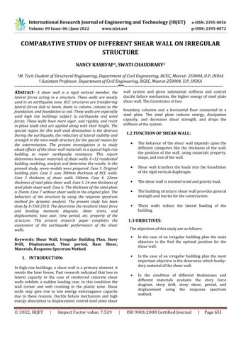
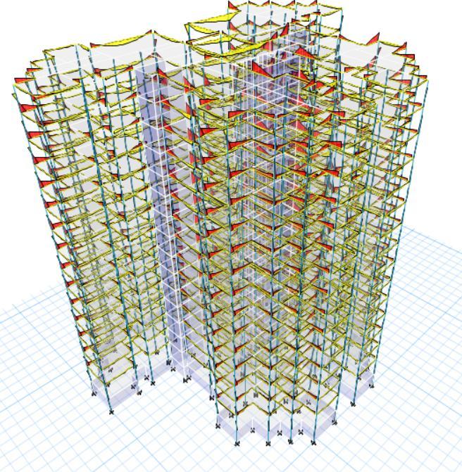
Figure: 1. 3DModellingoriginalplan, Case1
After the completion of all the modeling steps. We have performed the analysis process and checked errors. Go to the analysis menu and the first step is to apply the check model. The next step is the active degree of freedom, set loadcaserun,automeshsettingforfloorandwall,andthen run analysis. These are analysis steps are completed and read the last analysis. In this list check the stability of the model, linear static case using for p delta readings, RITZ model analysis, response spectrum x, y, and z direction Severaljointswithrestraintsandmosssources
Figure: 2 plan,Case6
International Research Journal of Engineering and Technology (IRJET) e-ISSN: 2395-0056
Volume: 09 Issue: 06 | June 2022 www.irjet.net p ISSN: 2395 0072
Thegraph4,5,6,7,8,and10 given belowdepictthe displacementalongthexandydirectionminimum steelplateshearwall.
The base shear for steel plate wall and RCC shear wallisdepictedintable2.
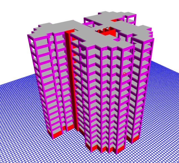
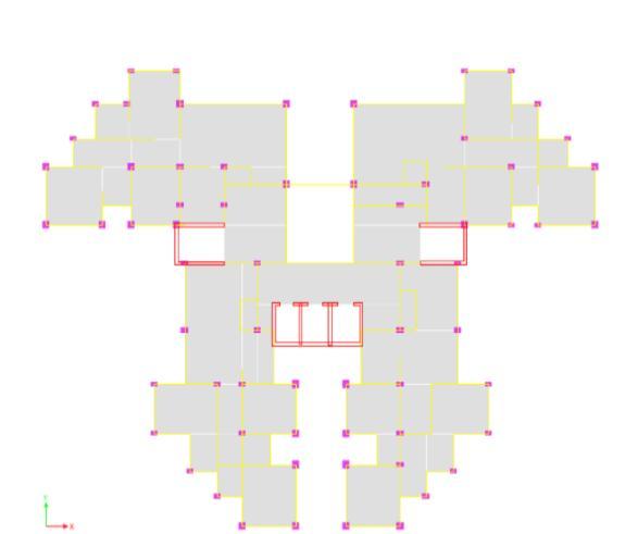
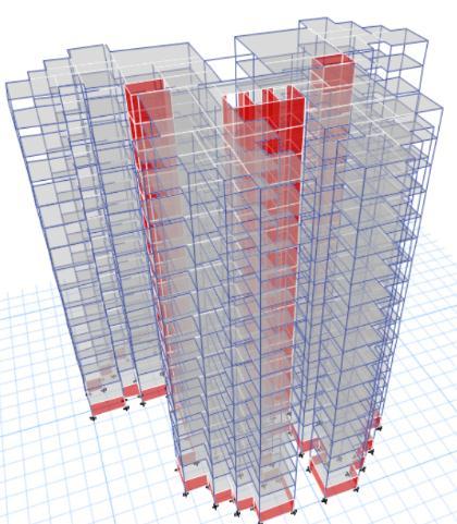
Figure: 3. 3DModelling, Case 6
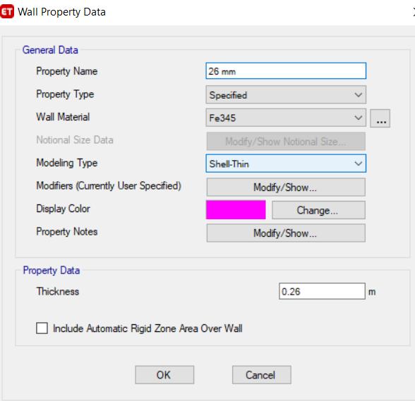
Figure: 4 case6 26mmthicknesswallmaterial
Whenthethicknessofthesteelplateisdecried,the steel plate wall case and the composite story drift isbeincreasing
Figure 8. Depicts that the time periods shear slightly reduces. when the thickness of the RCC shearwalldecreases.
Table2.Depictsthatthebaeshearisslightlywhen thicknessofsteelplate.
Whenthethicknessofthesteelplateisdecried,the steel plate wall andthe composite storydrift is be increasing.
Figure 5. X Direction Time Period Case
6.06 3.67 83.57 5 3.38 8 2.32 1 2.24 2.18 1 2 3 4 5 6 7 Case
1.213968 1.008931 0.967683 0.803141 0.619937 0.445971 0.000039 0.000038 0.000027 0.000006
EQ x EQ y EQX ( E.C) EQ Y ( E.C) EQX(+E.C)
9937 0.67 6917 0.57 6396 0.35 4436
8359 0.32 3872 1.27 6244 EQ (Y) 0.96 7683 1.07 1975 0.89 0181 0.49 1641 0.46 5721 0.44 2602 1.99 5065 E.Q X(+E C) 0.80 3141 0.87 3275 0.74 9098 0.47 4506 0.45 3696 0.43 4869 1.49 697 E.Q X( EC) 0.44 5971 0.50 4101 0.40 3693 0.23 4367 0.22 3022 0.21 2874 1.55 0734 E.Q Y(+E C) 1.21 3968 1.33 7798 1.20 798 0.64 3559 0.61 1245 0.58 2293 2.33 9465 E.Q Y( EC) 1.00 8931 1.11 1316 0.93 1937 0.54 3331 0.51 6175 0.49 1906 2.26 7242 Win dX 0.00 0006 0.00 0007 0.00 0006 0.00 0004 0.00 0003 0.00 0003 0.00 0022 Win dY 0.00 0038 0.00 0043 0.00 0035 0.00 0019 0.00 0018 0.00 0017 0.00 0099 Win d X 0.00 0027 0.00 003 0.00 0025 0.00 0014 0.00 0014 0.00 0013 0.00 01 Win d Y 0.00 038 0.00 0043 0.00 003 0.00 0019 0.00 0018 0.00 0017 0.00 0099
Table 1. MaximumDisplacement
Where, EQX=Earthquakex direction
EQ Y (+EC) Wind X Wind y Wind x Wind y 1.337798 1.111316 1.071975 0.873275 0.676917 0.504101 0.000047 0.000043 0.000007 0.000003
Figure 8. Displacement,mmincase1


EQX(+, EC)=Earthquakexdirectioneccentriccase(+, ) EQY(+, EC)=Earthquakeydirectioneccentriccase(+, ) EQY=Earthquakeydirection.
Figure 9. Displacement,mmincase2
International Research Journal of Engineering and Technology (IRJET) e-ISSN: 2395-0056
Volume: 09 Issue: 06 | June 2022 www.irjet.net p ISSN: 2395 0072
1.20718 0.931937 0.890181 0.749098 0.573696 0.403693 0.000066 0.000039 0.000035 0.000025 0.64359 0.543331 0.491641 0.474506 0.354436 00.234367 0.000019 0.000018 0.000014 0.000009
Figure 10. Displacement, mm in case 3
Figure 12. Displacement, mm in case 4
0.582293 0.491606 0.442602 0.434869 0.323872 0.212874 0.000019 0.000017 0.000013 0.000009 0.611245 0.516175 0.465721 0.453696 0.338359 0.223022 0.000019 0.000018 0.000014 0.000009
2.339465 2.267242 1.995065 1.550734 1.496765 1.276244 0.000094 0.000024 0.000022 0.000006
Figure 13. Displacement, mm in case 6

Figure 14. Displacement, mm in case 7
Figure 12 Displacement, mm in case 5
International Research Journal of Engineering and Technology (IRJET) e-ISSN: 2395-0056
Volume: 09 Issue: 06 | June 2022 www.irjet.net p ISSN: 2395 0072
TheRCCwallandsteelwallistraditionalinseismic behavior.
The minimum displacement in 26mm thickness of steelplateshearwall.
Intheoriginalplanwithoutashearwallwasgiven more displacement, time period, and story drift as tocomparedtotheplanwiththeoriginalplan.
Calculation of the values manual and software almostsameresults.
[1] I.S 1893(Part 1):2016 Indian Standard Criteria for earthquake resistant design of structure general provision andbuilding(sixthrevision).
[2] I.S 875 (Part 3):2015 Indian Standard Design loads (other than earthquake)for buildingandstructure codeof practice(part3)windload(thirdrevision).
Base Shear ( maximum)
S.NO EQ X EQY RSZ Shear X dir Shear Y Shear Z
Case 1 0.05092 0.024001 0.7971006 580.0522 273.4041 386.7015
Case 2 0.08803 23931576 6370355 0.0001255 34110.93 0.666667
Case 3 0.00585 0.240707 0.9630144 55.167482 2269.565 0.666667
Case 4 0.10907 2419299 2501971 0.0003958 8779.972 0.666667
Case 5 0.00283 0.242372 2.5740292 9.968838 854.9764 0.666667
Case 6 0.02483 0.000099 0.2976071 757.47249 3.020493 0.666667
Case 7 7.5E-05 0.207288 0.3431188 1.9847353 5485.5 0.666667
Figure :15. Force/Stress Diagram Case 1 Table 2. Maximum Base Share
The maximum time period is without the shear wallinoriginalplanandtheminimumtimeperiod isthicknessofsteelplatein26mm.
[3]I.S875(Part2):1987IndianStandardCodeofpractice for design loads (other than earthquake) for building and structurepart2ImposedLoad(secondrevision).
[4]I.S875(Part1):1987IndianStandardCodeofpractice fordesignload(other than anearthquakefor building and structures) Dead Load the unit weight of building materialsandstoredmaterials(secondrevision).
[5] I.S 13920: 2016 Indian Standard Ductile design and detailing of a reinforced concrete structure subjected to seismicforces Codeofpractice(secondrevision).
[6] Maksudul Haque, Hasibul Hasan Rahat, Rifat AL Saif, S. Reza Chowdhury. April 2018. Analysis of shear wall location due to the earthquake. Effect in high rise RCC structure(volume.5)
[7]C.j.GAN,X.L,Lu,W.Wong.October2018,Beijing, China. Seismic behavior of steel plate reinforced concrete shear wall.
[8] I.S 456:2000 Indian standard Plain and reinforced concrete codeofpractice(Fourthrevision).
[9] I.S 800: 2007 Indian Standard General Construction in Steel codeofpractice(Thirdrevision)
The time period slightly reduces when the thickness of the RCC wall and steel plate is decreased.
The story drift decreases in the case of RCC shear wall and increases in the case of steel plate shear wall.
[10] Youssef I. Agag, Mohamed E. El Madwy, Raghda I. Halima (vol. 7 issue 2, February 2019) the effect of shear wall positions and dimension variation on the analysis of themulti storybuilding.
International Research Journal of Engineering and Technology (IRJET) e-ISSN: 2395-0056
Volume: 09 Issue: 06 | June 2022 www.irjet.net p ISSN: 2395 0072
[11]DipanduBhunia,Vipul PPrakashandAshokDpadey. Aconceptualdesignapproachofcoupledshearwalls.2013.
[12]SeyedMohamadseyedkolbadi,NematMassani,Seyed Mahdi Kalbadi , and Masound Mirtaneri. “ Analysis parametericsensitivityonthecyclicBehaviorofsteel wall. (volume2021,ArticleI.D3976793).