International Research Journal of Engineering and Technology (IRJET) e ISSN: 2395 0056

Volume: 09 Issue: 06 | June 2022 www.irjet.net p ISSN: 2395 0072
International Research Journal of Engineering and Technology (IRJET) e ISSN: 2395 0056
Volume: 09 Issue: 06 | June 2022 www.irjet.net p ISSN: 2395 0072
1MTech student L.J University, Ahmedabad, India. 2 Assistant Professor, civil engineering department, L.J University, Ahmedabad, India ***
Abstract Shear walls are ordinarily used in excessive earthquake susceptible areas, as they are tremendously inexperienced in taking the masses, and in excessive upward thrust homes in which massive column length isnotviableand the consignment is additional. Steel concrete composite,steel, and R.C.C. choices are taken into thought for the comparative study. AN equal static approach of analysis was applied. For modeling of composite, steel, and R.C.C. structures, the ETABS software system program is utilized, and also the outcomes are compared. The analysis is the methodology of decidingthe conduct of the form below distinct load mixtures. style is the system, that demands the proper specification of the form. mistreatment software package program analysis and layout system are completed. If there is any surprising shift, it'sgoing to cause constructing stiffness/ torsionalinstabilityiftheform is stricken with the help of employing a sturdy seismic fore or with the help of employing a few completely different a lot of less horizontal forces. The improvement methodology is employed and during this, it's initially taken into the thought that the scale of the shear wall square measure identical withinside the development when that the analysis is dead, and since that, the failing shear wall dimensions square measure changed to overcome the full form, thereby optimizing for no. of instances until the full structure is powerful to resist the force. There square measure many structural parameters that have a bearing on the general performance of the structure as story drift, base shear, and story displacement that affected the behavior of the structure towards the wind and seismic masses. The optimized shear wall is also determined by the outcomes of shear force, Bending Moment, story shear, story displacement, story drift, and quantity of concrete and steel.
Key Words: Shear wall, ETABS, Earthquake loads, Load combination, Base shear
The layout of tall homes basically includes a conceptual layout,approximateanalysis,initiallayout,andoptimization, to securely convey the gravity and lateral masses. The primary motive of all sorts of structural structures used withinside the constructing sort of systems is to transfer gravitymasseseffectively.
Themaximumnotunusualplacemassesasaconsequenceof theimpactofgravityareuselessload,stayload,andsnow
load.Besidesthoseverticalmasses,homesalsoaresubjected tolateralmassesbecauseofwind,earthquakeforces.Lateral masses can broaden excessive stresses, produce sway movement, or cause vibration. Therefore, it's miles very criticalfortheshapetohaveenoughpoweragainstvertical massescollectivelywithgoodenoughstiffnesstofaceupto lateralforces.
The static and dynamic structural responses of excessive upward thrust homes are ruled with the aid of using the distributions of transverse shear stiffness and bending stiffness consistent with storey. “Making changes to the structureswithinsidetheconstructingormaybetheshape itselfsoonerorlaterafteritsinitialcreationandoccupation.”
Providing Lateral Strength to the building: Shear Wall must provide lateral shear strength to the buildingtoresistthehorizontalearthquakeforces, wind forces and transfer these forces to the foundation.
Providing Lateral Stiffness to the building: Shear Walls provide large stiffness to building in the directionoftheirorientation,whichreduceslateral swayofthebuildingandthusreducesdamagetothe structure.
International Research Journal of Engineering and Technology (IRJET) e ISSN: 2395 0056
Enoughwell distributedreinforcements.
ShearwallCost effectivenessrespectofearthquake.
Minimized damages to structural and Non structural elements.
Ratioofbreadth/width>0.4
Finishedcornersarepossible.
Clearsurfacewithoutanyoffsetispossible.
Normallylessconsumptionofbricks/blocks.
Shearwallsrunalongthefulllengthofwalls.
Thelateralloadisresistedbysheardeformation.
The shear wall system is more efficient for high rise structures.
Shearwallcross sectionislikeaverticallyorientedwide beam.
Morecarpetareaisavailableascomparedtothecolumn beamsystem.
[1] BuildingR.C.C.isbeingmodeled,studied,anddeliberated in this report. Shear wall structure through the state of affairs is a call for Vs functionality ratio evaluation accompaniedtothetraitsofsegmentshearwall.Considering the earthquake and wind forces, this may be advanced throughthepreciseversionproducedatEtabs.Theprimary intention of this plan is to look at and examine diverse fashions of Shear partitions the usage of ETABS is now practicedinthedirectionofreachingthemostadvantageous placement of approximately Shear partitions within the shape.
The constructing is effectively built using ETABS with the havealookatofreactionspectrumturnedintoappliedinthe directionofdegreeconstructing'sperformance.Thegadget labored admirably additionally the effects have been mentionedbelow.
1.Storeyflowapproximatelyshapebewithintheboundary inthevicinityofclauseno7.11.1ofIS 1893(Part 1):2002.
2. Storey Rigidity approximately shape be within the boundaryofclauseno4.20ofIS 1893(Part 1):2002.
3.Duetothelifeofshearpartitionsoneachcapacitybend location,theharmthatcouldshowupbecauseofwindand earthquakeforcesmaybemonitoredinthisproject.
L. Rahul, M.Akbar, M.Sriraman [2] Shear partitions are vertical factors of a pressure resisting machine that is horizontal. They are built to behave in opposition to the consequencesoflateralhundredswhichcanbeperforming attheshape.Inresidentialconstruction,shearpartitionsare immediatelyoutsidepartitionsthatshapeafieldthatgives lateralassistancetotheconstruction.Lateralhelpisdueto wind,earthquakes,theburdenoftheshape,andoccupants. These hundreds can tear or shear a construction apart. Reinforcing a body with the aid of using attaching an inflexiblewallinteriorcontinuestheformofthebodyand forestallsrotationonthejoints.Especiallyinhigh upward thrusthomesthataresubjectedtoseismicforcesandlateral windforces.Shearwallhomesareforresidentialfunctions to deal with 100 500 populations consistent with construction.
Dynamic linear evaluation of the usage of the reaction spectrumtechniqueisfinishedandlateralloadevaluationis completedforshapewithRCshearwallandSteelplateshear wall.Resultsareascomparedfortheearthquakeforcesand abendingsecondofeachcase.Itislikewisedeterminedthat lateralforcesaredecreasingwhiletheshearpartitionsare introduced atthe proper placesofframeshaving minimal lateral forces. Therefore, it's far inferred that Steel plate shearpartitions(t=6mm)aregreaterproofagainstlateral hundredsinanabnormalshape.
Authors: M. Pavani, G. Nagesh Kumar, Dr. Sandeep Pingale [3] Thebuildingspresentontheslopingfloorare veryexceptionalfromtheonesontheplainground,inthe sloping ground, the buildings are very abnormal and unsymmetrical in horizontal and vertical planes. The buildings in the sloping ground motive extra harm in the course of earthquakes because, in the sloping ground, the shapeisbuiltwithuniquecolumnheights.Inthisexamine the3 Danalyticalversionof10storiedbuildings,theplanof every configuration consists of four bays withinside the Y courseandsixbayswithinsidetheXcoursethat'ssavedthe identicalforallconfigurationsoftheconstructingframe,the slope became selected in among zero to 30 degrees. The shapewasefficientlyconstructedthroughtheuseofETABS andtheresponsespectrumevaluationwasusedtomeasure thebehavioroftheshape.Theshapeisexecutedadmirably andtheeffectsarementionedbelow.
Theshapenownolongerbetheidenticalformallround hasmodifiedthedisplacementoftheshapeinXandY course.
DisplacementisextrainXcoursethaninYcourse.
The tale waft is likewise very excessive whilst in comparisontotheYcourse.
Volume: 09 Issue: 06 | June 2022 www.irjet.net p ISSN: 2395 0072 © 2022, IRJET | Impact Factor value: 7.529 | ISO 9001:2008 Certified Journal | Page609
International Research Journal of Engineering and Technology (IRJET) e ISSN: 2395 0056
Volume: 09 Issue: 06 | June 2022 www.irjet.net p ISSN: 2395 0072
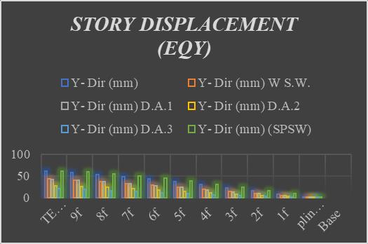
Thequalitymannertolessenwaftanddisplacementfor thedurationoflateralloadingistocontainashearwall inanunevenconfigurationineachdirection.
Table 3.1 GENERAL DATA
DESCRIPTION DATA
Dimension of the plan : 25x13.5m
No. of stories : 10
Floor to floor height : 3.15m Type of soil : Medium Support condition : Fixed
Table 3.2 MATERIAL PROPERTIES
DESCRIPTION DATA
Grade of Concrete (Beam) : M25
Grade of Concrete (Column) : M25 Grade of Concrete (Slab) : M25 Grade of Steel (Beam & Column)
: Fe500 Grade of Steel (Slab) : Fe500
Table 3.3 EARTHQUAKE PARAMETERS
DESCRIPTION DATA Zone : III Zone factor : 0.16 Importance factor, I :- 1.5 Response reduction, R : 5
Model 1(G+10w/oS.WALL)
Table 3.4 SIZING OF COLUMN & BEAM MEMBERS
DESCRIPTION DATA
Column : 0.45mx0.75m
Beam : TB:0.30mx0.60m MB:0.45mx0.55m(terrace) SB:0.30mx0.45m
3.2 Model 2 (G+10 w S. WALL)
Table 3.5 SIZING OF COLUMN & BEAM MEMBERS
DESCRIPTION DATA
Column : 0.45mx0.75m
Beam : TB:0.30mx0.60m MB:0.45mx0.55m(terrace) SB:0.30mx0.45m
3.3 Model 2 (G+10 w S. WALL) (D.A.1)
Table 3.6 SIZING OF COLUMN & BEAM MEMBERS
DESCRIPTION DATA
Column : 0.45mx0.75m
Beam : TB:0.30mx0.60m MB:0.45mx0.55m(terrace) SB:0.30mx0.45m
Wall : 230mm
3.4 Model 2 (G+10 w S. WALL) (D.A.2)
Table 3.7 SIZING OF MEMBERS
DESCRIPTION DATA
Column : 0.45mx0.75m
Beam : TB:0.30mx0.60m MB:0.45mx0.55m(terrace) SB:0.30mx0.45m
Wall : 230mm
International Research Journal of Engineering and Technology (IRJET) e ISSN: 2395 0056
Volume: 09 Issue: 06 | June 2022 www.irjet.net p ISSN: 2395 0072
Table 3.8 SIZING OF MEMBERS
DESCRIPTION DATA
Column : 0.45mx0.75m
Beam : TB:0.30mx0.60m MB:0.45mx0.55m(terrace) SB:0.30mx0.45m
Wall : 230mm
Table 3.9 SIZING OF MEMBERS DESCRIPTION DATA
Column : 0.45mx0.75m
Beam : TB:0.30mx0.60m MB:0.45mx0.55m(terrace) SB:0.30mx0.45m Wall : 230mm
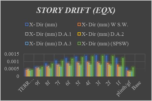
Similarly,another12modelsofG+15andG+20havebeen analyzedandfromthat,itisconcludedthat
1. Whenincomparisontoabuildingw/oashearwall, thebuildingwiththeshearwalliseffective.
2. Whencomparedtoatypicalbuilding,theweightofa buildingwithashearwallisrelativelymore.
3. When it comes to story stiffness steel plate shear wallhasalittlebitlessstorystiffnesscomparedtoabuilding w/oashearwall.
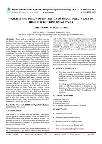
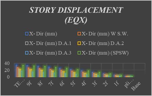
4. Whenitcomestostorydisplacementbuildingwitha shearwall(D.A.3)hastheleastdisplacementoftheothers.
5. In short, building with a shear wall is more economicalthanbuildingw/oashearwall,andtheeconomy ofashearwalldependsonthematerialsused,arrangement andconvenienceofconstructionofashearwall.
[1] Institute for steel development & Growth, "B+G+40 Storied Residential Building with Steel Concrete CompositeOption”IndiaDec2007.
[2] M.Nageh,“HowtoModelandDesignHighRiseBuilding UsingETABsProgram”Cairo2007.
[3] M. Willford, A. Whittaker and R. Klemencic, “Recommendations for Seismic Design of High Rise Buildings” Council of Tall building and Urban habitat Feb2008.
[4] J.ZilsandJ.Viis,“AnIntroductiontoHighRiseDesign” StructureMagazineNov2003.
International Research Journal of Engineering and Technology (IRJET) e ISSN: 2395 0056
[5] IS: 456, Code of practice for plain and reinforced concretecodeofpractice,BureauofIndianStandards, NewDelhi,2000.
[6] IS: 1893, Criteria for earthquake resistant design of structures general provisions for buildings, Part 1, BureauofIndianStandards,NewDelhi,2002.
[7] IS: 875, “code of practice for design load (other than earthquake) for buildings and structures” Bureau of IndianStandards,NewDelhi,2002.
[8] IS: 800, Code of practice for general construction in steel,BureauofIndianStandards,NewDelhi,2007.
[9] AISC360 05,Specificationofstructuralsteel building, An American national standard, American Institute of SteelConstruction,Inc.,2005
[10] IS:11384,Codeofpracticeforcompositeconstructionin structural steel and concrete, Bureau of Indian Standards,NewDelhi,1985.
[11] Esmails.epackachim.samadzadands.r.mirdhaderi― studyofRCshearwallsystemina56 storeytallbuilding (14WCEE 2008).
[12] Abiffazlshamsai,loghmanrahemi,kamalrahemi,saber peroti―arangementofshearwallsincontroloflateral displacement of 16 and 32 storey concrete frames (WASJ 2012).
[13] Peter K. Dean1 and Harry W. Shenton (2005), “Experimental Investigation of the Effect of Vertical LoadontheCapacityofWoodShearWalls”,Journalof StructuralEngineering;ASCE,pp1104 1113.
Links of the photos of the models https://drive.google.com/drive/folders/1_cPPWc7gYtarDM vNHWlGJpMN7TlfC0yD?usp=sharing
Volume: 09 Issue: 06 | June 2022 www.irjet.net p ISSN: 2395 0072 © 2022, IRJET | Impact Factor value: 7.529 | ISO 9001:2008 Certified Journal