International Research Journal of Engineering and Technology (IRJET) e ISSN: 2395 0056

Volume: 09 Issue: 06 | June 2022 www.irjet.net p ISSN: 2395 0072
International Research Journal of Engineering and Technology (IRJET) e ISSN: 2395 0056
Volume: 09 Issue: 06 | June 2022 www.irjet.net p ISSN: 2395 0072
1Assistant Professor, Dept. of E&C Engineering, GLA Mathura 2Profesor & Director IQAC, Dept. of E&C Engineering, GLA Mathura ***
Abstract This paper projects a thorough comparative study of the development and validation of control analysis of a model based heat exchanger system for different controllers such as feedback, feedback plus feed forward and internal model controller to control the temperature of product inasystem.Forcomparativeanalysisanexample of Heat exchanger system is considered in this study. For analysis of system behavior a mathematical model is formulated and different control algorithms are developed with the help of sensory system. The temperature is delimited at the desired set point automatically The performance of considered control strategies are assessed on the basis of transient response criterion (overshoot and settling time) and error based criterion (Integral of absolute error and square error for set point). On the basis of performed studies for a second order plus dead time system, it can be inferred that internal model control outperforms feedback PID and feedback plus feed forward controller.
Key Words: HeatExchanger,PID,Temperaturecontrol, Feedback Controller, Feedforward Controller, Internal ModelController.
Pressure,level,temperatureandflowarethemaincontrol parameters on which most of the process industries rely forcontrollingbothsetpointandloadvariations.Inaheat exchangerthemainoperationistransferofheatwhichcan be fluid to fluid or gas to gas [11]. The modeling and controllingthedynamicsofheatexchangeriscomplexdue to its non linearity and poor dynamics. Finding a good controlalgorithmisoneofthechallengingtasksonwhich the design of heat exchange controller depends. To develop this controller a system designer needs an accurate mathematical model of the entire process (with all control parameters) and then should consider other aspects like process uncertainty, measurement noise and robustness of the system. A controller should perform in two operating regimes: The first one is servo control in whichset pointtrackingisthemainconcernandtheother one is regulatory control where the focus is on load disturbance rejection and maintaining steady state conditions. So this study will focus on estimating the performance of some distinguished control algorithms to controlthetemperatureofheatexchangersystem.
What are the expectations from an industrial control system? It should have a fast response to transients like inputvariationandloadvariation.Itshouldexhibitlowest possible error at steady state and lowest possible settling time for any disturbance induced. So If summarized the primary objective of a controller is low overshoot, minimum settling time and minimum steady state error. Processes like temperature control, valve control are individually single order control system which probably may or may not have a delay but a heat exchanger is derivedbyintegrationofthesesingleordersystemswhich makes it a second order system with a dead time. So the transfer function of a heat exchange system will be a second order plus dead time (SOPDT) function and it would need a second order PDT mathematical model to design its controller. However, there are approximations thatwillbeusedinthisstudytoconvertSOPDTmodeltoa second order systems without dead time or delays. This will enable us to estimate the tuning parameters for the processcontroller.
Using a PID control configuration for a process controller hasbeenvery popularsince itsinceptionintheindustrial and automation control. According to estimation, 98% systems controllers which are employed in this industry are PID controllers. The reason for their wide acceptance is: their simpler structure and implementation, low cost and ease in understanding the behavior of the individual control actions. However, using only PID controller as a controlstrategyinyourprocessmaynotalwayscoverthe entire objective of controlling the system. A single PID controllercaneitherprovidebetterservoactionor better regulation action. But in real time problems, it is usually desired that the control strategy should provide both desired regulation. There are established tuning rules for firstorderandsecondordercontrolsystemsbutwhenwe add delay to these systems then it changes order for it which makes it complex to tune. So for such cases best possible assumptions are to remove these delays and compensate them system time constant so as to make it standard second order process control model. This study revolves around comparing the industry best control algorithm for a heat exchange system. It will present 3 different types of controllers, all designed to achieve the control objectives declared at the beginning of this study. Firstly, would be a conventional PID controller, which is themostcommonlychosenapproachforaprocesscontrol because of its simplistic nature [6]. After that a more
International Research Journal of Engineering and Technology (IRJET) e ISSN: 2395 0056
Volume: 09 Issue: 04 | Apr 2022 www.irjet.net p ISSN: 2395 0072
advancedfeedback control witha feed forwardcontroller is applied to understand the improvement over conventional PID i.e. comparison of desired robustness, system stability and how well they control the overshoot. The feed forward controller when combined with a feedback controller worked better than conventional PID alone but still there was a scope of improvement visible. To further improve the control performance a most advancedindustrialcontrolmethodknownastheinternal method controller was implemented on the same system. IMC gained widespread acceptance because of single control variable of the entire system which is the closed looptimeconstant.Furthertoit,asyouwillgothroughthe designyouwillfindotheraddedreasontouseit.
This paper is organized as follows: Section 2 provides a preliminary idea about heat exchanger and individual process transfer functions. Section 3 presents different control algorithms and controllers modeling. Section 4 provides the problem formulation where the mathematical modeling of the heat exchanger is illustrated. It also shows simulation results of different controllers for set point regulation as well as disturbance rejection. Finally, the conclusion is provided in Section 5. In this study MATLAB Simulink platform is used to perform system level simulation and derive the tuning parametersinallcontrolstrategies.
In the process industries, heat is transmitted via radiation by mixing of hot and cold fluids or by conduction through thewallsofaheatexchanger[10].Therearedifferenttypes ofheatexchangerusedinindustrieswhicharecategorized with respect to construction, transfer process, flow and phase. Shell and tube heat exchangers are the most versatile type of heat exchangers applicable for a wide range of operating temperatures and pressures [8, 9]. These types of heat exchanger make availability of relatively large ratio of heat transfer area to volume and weight. These are quite easy to construct in an inclusive collection of sizes and configurations. They are mechanically rugged enough to withstand normal shop fabrication stresses, shipping and field erection stresses, andnormaloperatingconditions.It’speriodicmaintenance andcleaningiseasyduetoitssimplestructurewhicheases disassembly so that those components most subject to failure gaskets and tubes can be easily replaced. They are widely used in the process industries, in conventional and nuclear power stations, refrigeration, power generation, heating, air conditioning, chemical processes, and medical applications.
A shell and tube heat exchanger is an extension of the double pipe configuration (single pipe within a larger pipe). As its name indicates, this type of heat exchanger
comprises of a large pressure vessel i.e. cylindrical shell withabundleoftubesinsideit.Colderfluidrunsinsidethe tubes, and hotter fluid is allowed travel over the tubes (through shell) which will then transfer heat to the colder tubes eventually raising the temperature of colder fluid. Theheatexchangetubesmightbemadeupofseveraltypes of tubes: plain, longitudinally finned, etc. In thisstudy, the heat exchanger considered is a fluid fluid two pass countercurrent type and real time experimentation is performed for model identification of laboratory shell and tubetypeheatexchangersystem.Thesolepurposeofusing the heat exchanger is to control industrial fluid temperaturecomingoutofthissystem.
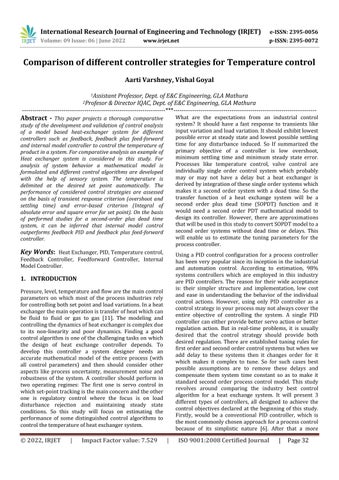
Figure1showsarealtimeworkingblockdiagramofaheat exchanger system. The cold water is the input which suppliesfromtheoverheattanktotheshellsideoftheheat exchanger.Temperaturesensormeasuresthetemperature of output fluid. A 3 wire PT 100 RTD is used to measure the temperature as it can withstand high temperature while it maintains stability and is connected to the transmitter. The temperature transmitter drives the measurement signal to the controller. The RTD circuit produces a standard output of (4 20) mA which is proportional to the temperature. Then this output is read by the main controller using a data acquisition (DAQ) device (Analog to digital converter). The controller processes the error signal and decides the needed control action for temperature control. The controller unit sends thecorrespondingcontrolsignalto(currenttopressure)a converter via another DAQ (Digital to analog converter) device converting it in range of (4 20) mA and output of the converter is a signal in (3 15) psi. The current to pressureconverteriscalledasactuatorwhichconvertsthe outputcurrentofcontrollertoappropriatepressuresignal. The pressure signal is transmitted to control valve which acts as a final control element. The control valve triggers according to the control signal and allows the necessary steamtoentertheheatexchangerforcontrollingtheoutlet temperatureofheatexchanger.
The PID controller algorithm comes inside the main controller which takes the important processing of comparing the input received from sensor, comparing it witha referencetemperatureandthen sendinga signal to valve to take action to reach that desired temperature. A mathematical modeling of this system thus involves the transfer functions of all the individual processes to create thecompleteheatexchangesystem.
International Research Journal of Engineering and Technology (IRJET) e ISSN: 2395 0056
Volume: 09 Issue: 04 | Apr 2022 www.irjet.net p ISSN: 2395 0072
2.2.1
Considering temperature system as a first order system withtimedelayhavingtransferfunction,Gp[13]
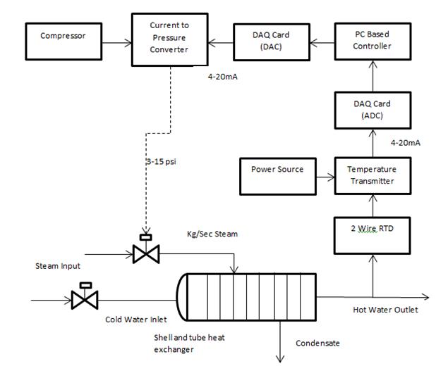
Figure 1:Blockdiagramofheatexchangersystem
An actual heat exchanger was fabricated [1] according to the derived dimensions by carrying out the validation of this theoretical model based heat exchanger. After the setup on running practically in open loop configuration the derived results at 800 rpm of hot water pump and givingastepinputof50℃areasunderdepictedinTableI.
Time (sec) Temperature( c) 0.5 25.00 7.71 25.14 21.7 29.03 38.8 31.89 70.27 35.77 114.69 39.53 181.83 42.75 257.65 44.19 297.73 44.80 409.62 45.37 486.44 45.62 573.28 45.76 596.66 45.85 596.66 45.92
Table 1: ReadingsofPracticalPerformanceinOpenLoop: 800rpm&50℃
In the heat exchanger system, actuator, valve, sensor are mathematically modeled using the available experimental data[1].
(1) N=FinalvalueofOutput; M=finalvalueofthestepinput; M=50(Stepinput) fromTable1; N=46(Responsefinalvalue) fromTable1; Delaytime=0.5s GP= GP=
2.2.2
Let’sconsidercontrolvalveT.F.anddisturbances; Datareference[1]
Maximumtravelofcontrolvalveisgivenas=15mm. Timeconstant=3sec PressureRange=(3 15)psi Controlvalvegain
TransferFunctionControlValve(Actuator) GP= GP= (2)
2.2.3 Sensor Transfer Function
Considering Control Valve and Sensor T.F. with filter coefficient
Datareference[1]
International Research Journal of Engineering and Technology (IRJET) e ISSN: 2395 0056
Timeconstant=1 2sec(considering1sec)
Range= ℃
Sensorgain
TransferFunctionofsensor
H(s)= (5) H(s)= (6)
Datareference[1]
DisturbanceGain=1
TimeConstant=3sec
TransferFunctionofDisturbance
Gd(s)= (7)
Gd(s)= (8)
Theheat exchangerissupportedbyfeedbackandoverride control system to control, modify and regulate the temperature of water. PID Controller, Feed Forward ControllerandIMCControllerarethreemostprevalentand usedmethodsforcontrol.
Thiscontrollerisordinarilyestablishedbycombiningthree termsviz.,proportionaltermdifferentialtermandintegral term together in a linear form. The proportional term reduces error due to disturbance, integral term eradicates steady state error and the derivative term dampens the dynamic response, and hence improving the system stability. This controller is easy for development and implementation which also makes it available for widely usedinsolvingprocesscontrolproblems.
Figure 2 shows the functional block diagram of PID controller based control system where a PID controller mathematicalmodelrepresentedasfollows;
* + (9)
PIDcontrollersaretunedwithvarioustuningmethodslike Zn Ns, Cohen coon [7], GM PM, IMC etc. However, the internal model control (IMC) tuning gives the best results for PID parameters. So the paper uses IMC tuning parameters.
3.1.1. Internal Model control (IMC) Based PID controller
Theheatexchangerprocesscontroltransferfunction isgivenby: (10)
Step 1 Use Pade approximation to accommodate delay compensation
It can be approximated with zero order ‘Pade ’approximation[2] [ ][ ] (11)
Considering, Generating the second order delay equation to second orderwithoutdelay (12) Step-2 Formtheidealizedcontroller (13) (14)
Step 3 Addthefilter ̃ (15)
Volume: 09 Issue: 04 | Apr 2022 www.irjet.net p ISSN: 2395 0072 © 2022, IRJET | Impact Factor value: 7.529 | ISO 9001:2008 Certified Journal | Page35
International Research Journal of Engineering and Technology (IRJET) e ISSN: 2395 0056
Volume: 09 Issue: 04 | Apr 2022 www.irjet.net p ISSN: 2395 0072
(16)
Step-4 FindthePIDequivalentforIMCtuning (17) (18) [ ] ( ) * + (19)
Comparing with IMC based controller transfer function, gc(s),where * + (20)
Henceforth,IMC PIDtuningparametersderivedhereare ( ) (21) (22) (23) (24) ( ) (25) ⌈ ⌉ (26)
Thisis the IMC tuning for which will use to determine the parametersofthefeedback/PIDcontroller.Forthiswork
The parameters of PID controller can determine by using thisdataintheequations(22),(24)and(26),
Finding few more tuning points of PID in similar way for differentvaluesoffiltertimeconstant,
Afeedforwardalgorithmeliminatestheintrinsiclimitation of feedback control scheme i.e. in the feedback system the controller acts after the disturbance distorts the required control objective but a feed forward controller estimates theerrorandchangesthemanipulatingvariablebeforethe disturbance can affect the output. A feedback control cannot attain the desired steady state if frequent disturbances occur. To minimize the overshoot and get steadystate, feed forward control isused whichlimitsthe deviation caused by the disturbance which is necessaryto estimate for proper working of Feed forward control. Feed forward control cannot work alone, so it works
© 2022, IRJET | Impact Factor value: 7.529 | ISO 9001:2008 Certified Journal | Page36
International Research Journal of Engineering and Technology (IRJET) e ISSN: 2395 0056
Volume: 09 Issue: 04 | Apr 2022 www.irjet.net p ISSN: 2395 0072
alongside feedback control. A feed forward controller is used with the feedback (PID) controller introduced in the forward path of the process. It is expected that the combined effect of both feedback and feed forward controller improves the control strategy over standalone feedbackcontrol.
Looking at the above equation it is clear that filter time constant, , is the only tuning parameter for this feed forwardtransferfunction.
(30)
Now, this feed forward controller transfer function will be used in simulation model in the forward path of the process along with other system transfer functions and feedback controller with same P,I,D parameters but will be tuned with different filter time constant along with Feed forward controller. This is describedinFEEDFORWARDsimulationsection4.
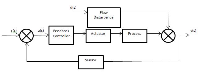
Infeedforwardcontrollerweprovidetheflowdisturbance as the input fluid. Figure 3 shows the block diagram Feed forwardcontrolalongwiththefeedbackcontrol.
The flow disturbance is measured or estimated and the feed forward controller tries to compensate the disturbance effect on the system. The processed signal from Feed forward controller and feedback controller are summedupandprovidedtotheprocess.
Thetransferfunctionoffeed forwardcontrollercanbe representedas (27)
Here, TransferFunctionoffeed forward controller
TransferFunctionofflowdisturbance
Feedingthevaluesofentireprocess,weget; (28) (29)
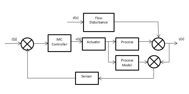
3.1.3. Internal Model controller (without PID )
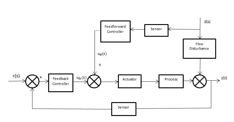
In the field of chemical engineering IMC (internal model control)isoneofthemostpopulartechniqueswhichoffers a translucent frame for control system design and tuning[4].The basic aim of introducing IMC is to limit the effects of error and disturbance caused by model mismatch. The process model derived can be a forward model or inverse model. The controller is carved out from theinverse model whereastheforward model is placed in parallelwiththeactualprocess.Thatisstandardmodeling method for IMC control strategy. The structure of internal model controller is shown in figure 4. Filter time constant, is introduced in the system to achieve good disturbancerejection.
Thetransferfunctionoftheprocessisshownineq. (31)
Step 1 Useasecond orderPadeapproximationfordead time
International Research Journal of Engineering and Technology (IRJET) e ISSN: 2395 0056
(32) Where ̂ (33)
Step 2 Factoroutthenon invertibleelements
(34) (35)
(36)
This study has considered combination of 3 performance parameters of the step response which can provide a better indication of the efficiency of the control algorithms. The considered parameters are maximum overshoot,settlingtime,IAEandISE.
4.1.1.Maximum Overshoot
Peakovershootisdefinedasthedeviationoftheresponse at peak time from the final value of response or desired value. It is the normalized difference between the peak of the time response and steady output. It is also called the Peak overshoot.
( ) (42)
Step 3 Addthefilter
(37) (38) (39) (40)
Fromtheaboveequation,theonlytuningparameterisλ andhenceIMCcontrollerissimple.
Step 4 FindtheTransferFunctionofIMCcontroller * + (41)
IMCMethoddoesnothaveanyP,I,Dtuningparameters;it onlyneedsfiltertimeconstant tobetunedwithbest possibleoutputs.
In this work different controllers are used to control the temperature of a shell and tube heat exchanger system. This section discussed the simulated study of the controller performance which is one of the widely researchedareaswhichdeterminetheperformanceofthe controllerbyvariousmethods.
Itisthetimerequiredfortheresponsetoreachthesteady stateandstaywithinaspecifiedtolerancebandofitsfinal value.Thetolerancebandistakengenerallyas2 5%.
In closed loop system the error signal is the difference between input signal and the feedback signal. IAE integrates the absolute error over time [5]. It doesn't add weighttoanyoftheerrorsinasystemsresponse.Ittends toproduceslowerresponsethanISEoptimalsystems,but usuallywithlesssustainedoscillation.
∫ (43)
4.1.4.
ISE integrates the square of the error over time [5]. ISE will penalize large errors more than smaller ones (since the square of a large error will be much bigger).Control systems specified to minimize ISE will tend to eliminate large errors quickly, but will tolerate small errors persistingforalongperiodoftime.Oftenthisleadstofast responses, but with considerable, low amplitude, oscillation.
∫ (44)
Where,e(t)istheerrorofsystem, isthetimeatwhich setpointor disturbanceisapplied.Inthisworktheset pointanddisturbancebothareappliedat t =0s.
Volume: 09 Issue: 04 | Apr 2022 www.irjet.net p ISSN: 2395 0072 © 2022, IRJET | Impact Factor value: 7.529 | ISO 9001:2008 Certified Journal | Page38
International Research Journal of Engineering and Technology (IRJET) e ISSN: 2395 0056
Volume: 09 Issue: 04 | Apr 2022 www.irjet.net p ISSN: 2395 0072
In this study of temperature control of a shell and tube heatexchangersystemisanalyzedforthedifferentcontrol mechanism i.e. PID, feed forward and IMC controllers respectively and the simulated study of the controller performance is discussed in this section. The simulations are carried out using MATLAB (version R2018) software, for set point tracking and load regulation. The transient responsei.e.peakovershootandsettlingtimeforunitstep responseofandtheerrorresponsesoffeedback,feedback plus feed forward and internal model controllers are summarizedinTable5.
Overshoot Settling time IAE ISE
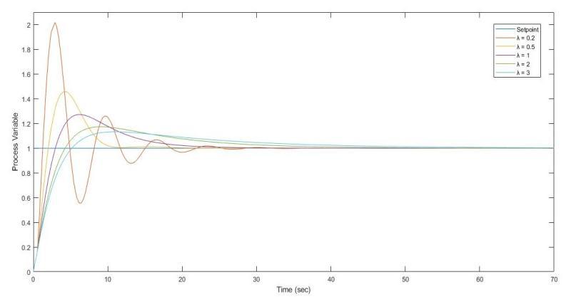
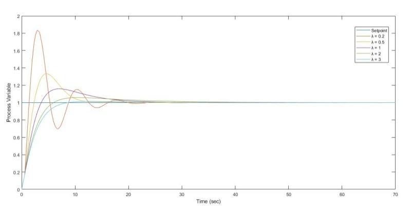
0.2 101.71 21.01sec 0.728 0.060
0.5 45.92 10.01sec 0.595 0.049
1 17.30 32.89sec 0.721 0.052
2 27.20 20.35sec 0.853 0.055
3 13.24 42.10sec 0.925 0.057
Table-2: ResponseofFeedbackPIDcontrollerfor differentvaluesof
Figure 7: ProcessVariablevariationinFeed forward controller
Overshoot Settling time IAE ISE
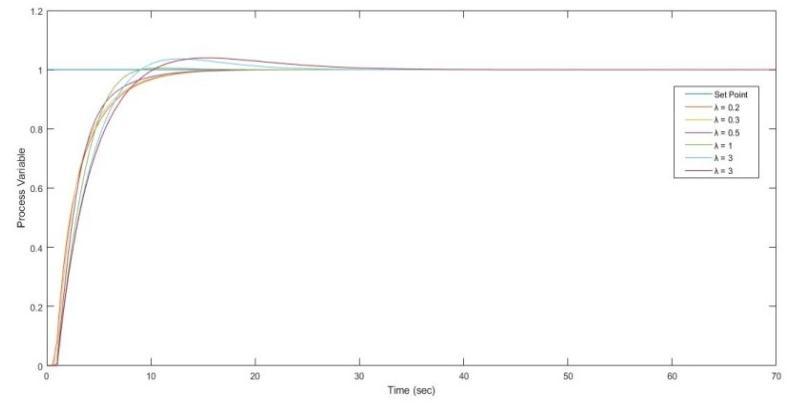
0.2 0.013 11.50sec 0.799 0.088
0.3 0.015 11.28sec 0.799 0.088
0.5 0.010 10.59sec 0.799 0.088
1 0.546 7.62sec 0.803 0.086
2 3.651 17.80sec 0.800 0.087
3 3.946 22.92sec 0.800 0.086
Table 4:ResponseofIMCcontrollerfordifferentvaluesof
Figure 6: ProcessVariablevariationinFeedbackPID controller
Overshoot Settling time IAE ISE
0.2 83.50 18.70sec 0.623 0.052
0.5 33.35 11.35sec 0.559 0.046
1 15.91 20.30sec 0.626 0.048
2 5.81 25.17sec 0.626 0.051
3 1.42 7.23sec 0.561 0.054
Table-3: ResponseofFeedbackFeed forwardcontroller fordifferentvaluesof
Figure 8: ProcessVariablevariationinIMCcontroller
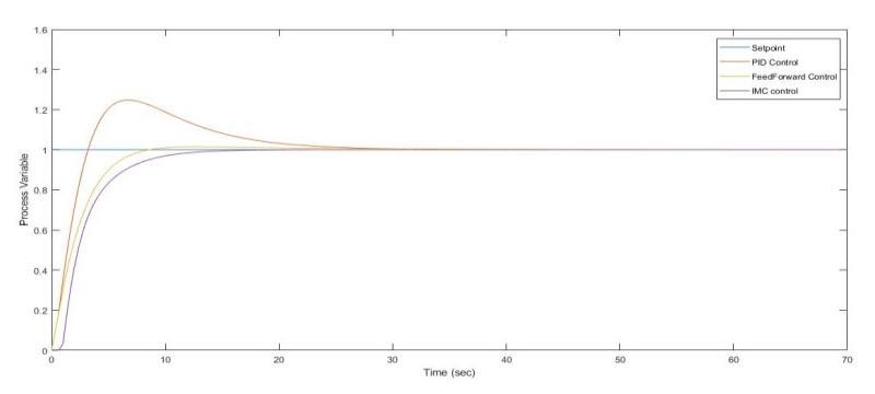
Figure 9: ProcessVariablevariationindifferentcontrol systems
International Research Journal of Engineering and Technology (IRJET) e ISSN: 2395 0056
Volume: 09 Issue: 04 | Apr 2022 www.irjet.net p ISSN: 2395 0072
Controller Overshoot Settlin g time IAE ISE
FeedbackPID ( ) 17.30% 32.89 sec 0.74 0.05
Feed forward 1.42% 7.23 sec 0.56 0.05
IMC 0.51% 7.64 sec 0.80 0.08
Looking over the simulation results, it is evident that at the best tuned filter time constant value, the overshoot and setting time is decreased significantly. The filter time constant is significance of filter cut off frequency and delay it introduces in the system. Because time constant decreasing means higher frequency cut off is being used, which is one of the reasons why lower time constants valuehavelowerovershootvalues.
Lookingattable5itcanbeconcludedthatevenwithbest filter time constant the PID and Feed forward control systemsarenotthatgoodasIMCControl.ComparingIMC with PID and Feed forward methods, it is visible that by choosing right filter time constant or filter frequency the IMC comes out to be best control strategy than other controllers.
In PID controller we set the parameters by using IMC tuningmethodtogetsatisfactoryresponse.Foraunitstep setpoint we foundovershootand large settling time both of which are undesirable. The feedback PID controller shows17.30%ofovershootand32.89secofsettlingtime. Then feed forward controller is added with feedback controller to avoid high overshoot of classical PID controller. The arrangement of feedback plus feed forward controller reduces the overshoot to 1.42 % and settling time to 7.23 sec. After that model based control (IMC) is used to minimize the overshoot further which displays an overshoot of 0.51% with the 7.64 sec settling time.
This paper presented a thorough comparative study between different control algorithms to control the outlet temperature of a shell and tube heat exchanger system. This work strives to find a best suitable method for the heat exchanger system which can give most satisfactory performance parameters of a system, i.e., tracking performance, disturbance rejection, and robustness. To achieve and analyze this, three different controllers have
value:
beentriedoutusingsomewidelyacceptedtuningrulesfor simpleconventionalcontrolstructures.
Firstly, wehave developed a mathematical process model of the heat exchanger through experimental data [1] and then cultivated the respective controller by using this process model along with the experimental data. The assessment of different controllers has been evaluated on the basis of transient characteristics and error indices. Fromthesimulationresults,itisfoundthatIMCcontroller outperformed the feedback and feedback plus feed forward controller. IMC gives good and reasonable result for both tracking performance as well as disturbance rejection. The feedback and feed forward controllers display a higher degree of overshoot and settling time while the internal model control negates the overshoot andtakesadaptablesettlingtime.
[1] Control Analysis Using Tuning Methods for a Designed, Developed and Modeled Cross Flow Water Tube Heat Exchanger, World Academy of Science, Engineering and Technology, International Journal of Mechanical, Aerospace, Industrial and Mechatronics EngineeringVol:8No:12,2014,ShaivalH.Nagarsheth, UtpalPandya,HemantJ.Nagarsheth.
[2] IMC PID Controller Designing for FOPDT & SOPDT Systems,INTERNATIONAL JOURNAL OFINNOVATIVE RESEARCH IN ELECTRICAL, ELECTRONICS, INSTRUMENTATION AND CONTROL ENGINEERING. Vol.4,Issue5,May2016,Miss.LondheP.P,Prof.Kadu C.B,Prof.ParvatB.J
[3] Simple PID Controller Tuning Method for Processes with Inverse Response Plus Dead Time or Large Overshoot Response Plus Dead Time, I Lung Chien,* Yu Cheng Chung, Bo Shuo Chen, and Cheng Yuan Chuang, Department of Chemical Engineering, National Taiwan University of Science and Technology,Taipei10672,Taiwan.
[4] Process control: modeling, design, and simulation, Chapter8,InternalModelcontrol,B.WayneBequette· 2003.
[5] IAE and ISE Performance Criterion Based Loop Filter Tuning of Transport Delay Phase Locked Loop (TD PLL)forSinglePhaseGridConnectedInverters,Mohd AfrozAkhtar&SumanSaha,AcademyofScientificand Innovative Research (AcSIR), CSIR CMERI Campus, Durgapur Scientist, CSIR Central Mechanical EngineeringResearchInstitute,Durgapur.
International Research Journal of Engineering and Technology (IRJET) e ISSN: 2395 0056
[6] Modeling and Control of Shell and Tube Heat Exchanger using MATLAB Simulation ,NANG SEIN MYA1, CHO KHAING2, EI THAR3, AYE MYA THANDAR4, International Journal of Scientific EngineeringandTechnologyResearchVolume.08,Jan Dec 2019,Pages:221 224.
[7] Review Paper on Comparison of various PID ControllersTuningMethodologiesforHeatExchanger Model, Sumit, Ms. Kajal, Department of Electrical Engineering,R.NCollegeofEngineering,Rohtak.
[8] D. P. Dash and A. S. Deshpande, “Design and Simulation of Fuzzy Controller for Heat Exchanger,” Int.J.Syst.Appl.,vol.3,no.13,pp.83 85,2013.
[9] S. Rajasekaran, “An Improved PID controller Design based on Model Predictive Control for a Shell and Tube Heat Exchanger,” Aust. J. Basic Appl. Sci., vol. 7, no.7,pp.679 685,2013.
[10] T. Kuppan, Heat Exchanger Design Handbook, Marcel Deker,2000,chapter1,pp.27 43.
[11] Dynamic Mathematical Model of a Heat Exchanger, Patel, A.M. and March, 2003, PhD Thesis, Chemical Engineering,UniversityofTennesseeatChattanooga.
[12] M. Jelali, “An overview of control performance assessment technology and industrial applications,” Control Engineering Practice, vol. 14, no. 5, pp. 441 466,2006.
[13] N. V. Suryanarayana, Engineering Heat Transfer, Penram International Publishing Pvt. Ltd, 2008, pp. 844 890.
[14] ImprovingthePerformanceofHeatExchangerSystem by better Control Circuits, Eslam Ezzat, Roshdy AbdelRassoul Ismail, International Journal of Computer Applications (0975 8887) Volume 121 No.11,July2015.
Volume: 09 Issue: 04 | Apr 2022 www.irjet.net p ISSN: 2395 0072 © 2022, IRJET | Impact Factor value: 7.529 | ISO 9001:2008 Certified Journal | Page41