International Research Journal of Engineering and Technology (IRJET) e-ISSN: 2395-0056

Volume: 09 Issue: 06 | June 2022 www.irjet.net p-ISSN: 2395-0072
International Research Journal of Engineering and Technology (IRJET) e-ISSN: 2395-0056
Volume: 09 Issue: 06 | June 2022 www.irjet.net p-ISSN: 2395-0072
1
, Hassan.E .Elkhidr2 , Gurashi .A Gasmelseed31Red Sea University, Department of Chemical Engineering, Port Sudan, Sudan 2Shendi University, faculty of science and Technology, department of chemistry, shendi, Sudan 3University of Science and Technology, Omdurman, Sudan ***
ABSTRACT:
A controlstrategy wasdeveloped fromHegleig to Khartoumrefinery .The distance between station is 250 Km ,eachstation has a controlsystemofthreeloops,theseare:loop1,controlsofadditivesrates,loop2and3 arethecascadeofviscosityasmastercontroller withtemperaturesecondarycontroller,thesehavethe dutyforcontrollingandreportingtotheSCADAsystemwhichintervenesasthe casemayrequiretoadjustthesetpoint.Thetransferfunctionsweredeterminedandtheoveralltransferfunctionsofthecloseandopen loopswerecalculated .Fromthesetuning andstabilityanalysiswereobtainedandcompared witheachother.Theseparameter were foundtobeinagreement .Theeffectandresponsesimulationwerealsodeterminedandfoundtobereasonablewithaverageoffsetof 0.484,and0.Thismeansthatalltheresponsesreachthefinalvaluewithoutanyovershoot.ItisrecommendVis breakingunithastobe installedatthecentralprocessingfacilities;particularlyifthereserveispromisingforsomemoreyearsofproduction.
Key Words: Control Strategy, cascade system, Waxy Crude oil, Khartoum refinery
1 Introduction:
Waxisacompoundofcrudeoilthatremainsinsolutionuntiloperatingconditionsarefavorabletoitsprecipitation,acondition causedbychangesinthe temperature pressureequilibriumofthecrudeoil.Uponprecipitation(crystallization),waxisdepositedon thecomponentsoftheproductionsystembyvariousmechanismsincludingmoleculardiffusion, sheardispersion,Browniandiffusion , and gravity settling .Brownian diffusion and gravity settling are not very significant in the dynamic condition obtainable in crude oil production Waxdepositionhasbeenreportedinallfacetsoftheproductionsystemincludingthereservoir,wellbore,tubing,flowlines, and surface facility .Wax deposition causes loss of production, reduced pipe diameter, and increased horsepower requirement, and negatively impacts production economic. The available remedial measure includes mechanical, chemical, and thermal techniques. Temperaturereduction/heatlossisadominantfactorinwaxproblems,aswaxbeginstoprecipitatefromcrudewhenthetemperature fallstoorbelowthecloudpoint(waxappearancetemperature) [1]
2 Tuning of cascade control:
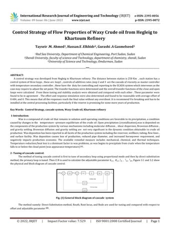
Themethodoftuningcascadecontrolisfirsttotuneofsecondaryloopusingproportionalmodeandthenbydirectsubstitution method,theprimaryloopistuned.ThenZ Nisusedtocalculatetheadjustableparameter , , , , Figure3.1and3.2show thephysicalandblockdiagramofcascadecontrol.
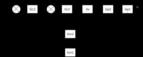
Fig. (1) General block diagram of cascade system
Themethodnamely:DirectSubstitutionmethod,Routh,Rootlocus,andBodeareusedfortuningandcomparedwithrespectto offsetandadjustableparameter [2]
3
International Research Journal of Engineering and Technology (IRJET) e-ISSN: 2395-0056
Volume: 09 Issue: 06 | June 2022 www.irjet.net p-ISSN: 2395-0072
The stability of the control system is very important and almost should be checked using different methods .The stability of system deepens on the location of the roots of the characteristic equation on argand diagram .The roots are determined by direct substitution ,bode diagram ,root locus and nyquist plot .The stability of the system are also determined by Routh criterion which has specialtechniquetoshowifthesystemcriticalstable,stableorunstablefromthesemethodstheadjustableparameterscanbeobtained usingZeigler Nicholstechnique[3]
3
Apply the Routh test on the closed loop characteristic polynomial to find if there are closed loop poles on the right hand plane. Evaluatedtheestablishlimitsonthecontrollergain.Generally,forann thorderpolynomial,weneed(n+1)rows.Thefirsttworowsare filled in with the coefficients of the polynomial in a column wise order .The computation of the array entries is very much like then negativeofanormalizeddeterminantanchoredbythefirstcolumn [4]
3 2 Direct substitution: Substitutess=іω in characteristic polynomial and solve for closed loop poleson Im axis. The Im and Re parts of the equation allow the ultimate frequency to be solved. Evaluated the ultimate gain and ultimate period ( )that can be used in the Ziegler Nicholescontinuouscyclingrelations.Andresultsonultimategainisconsistentwiththe Routh arrayanalysisandlimitedtorelatively simplesystem [4] .
Thisempiricalmethodisbasedonclosed looptesting(alsocalledon linetuning)ofprocesseswhichareinherentlystable,but wherethesystemmaybecomeunstable.Weuseonlyproportionalcontrolintheexperiment.Ifitisnotpossibletodisabletheintegral andderivativecontrolmodes,wesettheintegraltimetoitsmaximumvalueandthederivativetimetoitsminimum.Theproportional gainisslowlyincreaseduntilthesystembeginstoexhibitsustainedoscillationswithagivesmallstepsetpointorloadchange [5] .
Theideaofarootlocusplotissimple,ifwehaveacomputer.Wepickonedesignparameter,say,theproportionalgainKc, and writeasmallprogramto calculaterootofthecharacteristic. Polynomialforeachchosen valueofKcasin 0,1,2…..100,etc.The results (the values of the roots) can be tabulated or better yet, plotted on the complex plane. Even though the idea of plotting a root locus soundssosimple,itisoneofthemostpowerfultechniquesincontrollerdesignandanalysiswhenthereisnotimedelay.
Rootlocusisagraphicalrepresentationoftherootoftheclosed loopcharacteristicpolynomial(i.e.,theclosed looppoles)asa chosen parameter is varied .Only the roots are plotted. The values of the parameter are not shown explicitly. The analysis most commonly uses the proportional gain as the parameter .The value of the proportional gain is varied from 0 to infinity, or in practice, just"largeenough [4]
3 5 Bode Method:
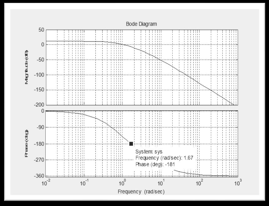
5BodeMethod:Bodeplotisdrawnforthesecondarylooptocalculatetheultimategainandultimateperiod,thentheultimategainfor primaryloopiscalculatedfromthesecondaryloop[2]
4 MATLAB Software:
MATLABisintegratedtechnicalcomputingenvironmentthatcombinesnumericcomputation,andvisualization,andahighlevel programminglanguage.TheMATLABsoftwarewasoriginallydevelopedtoamatrixlaboratory.Itscapabilitieshaveexpandedgreatlyin recent years and today it is a leading tool for engineering concepts in mathematics (15).Being able to plot mathematical functions and
International Research Journal of Engineering and Technology (IRJET) e-ISSN: 2395-0056
Volume: 09 Issue: 06 | June 2022 www.irjet.net p-ISSN: 2395-0072
data MATLAB, can be used in research, development and in industry. It is used in this research for tuning through different tuning techniques [6] .
5 Tuning of Loop1: AdditivesLoop: ProportionalController(P): 4.1 ( )( ) ( ) ( ) Fig. (2) Loop1 block diagram
Analysis and optimum settings: 5 1 Routh _Hurwitz Method: Thecharacteristicequationis: 1+OLTF=0 1 1+πl=0 2 ( )( )( )( ) ( )( )( )( ) KC=2.13
Theultimategain,Ku=2.13

5-2 Direct substitution method: Set S=іω ( ) ( )
2022, IRJET | Impact Factor value: 7.529 | ISO 9001:2008 Certified Journal
International Research Journal of Engineering and Technology (IRJET) e-ISSN: 2395-0056
Volume: 09 Issue: 06 | June 2022 www.irjet.net p-ISSN: 2395-0072
Takingtheauxiliaryequationandfromthattheimaginarypartofthecharacteristicequationisequaltozero:
5 3 Applying Ziegler Nichols method:
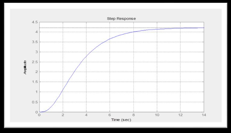
Table (2): Ziegler Nichols adjustable controller parameters for additives loop for Routh _Hurwitz (sec) (sec) Kc Typeofcontroller 1.065 P 3.21 0.553 PI 0.48 1.93 0.738 PID 5 4 Offset investigation: ( ) ( ) ( ) Kc=1.065fromtuning, ( ) Where: ( ) Magnitude of unit step change =1 = ( ) [ ( ( ) ( )( )( )( ) )] ε Using MATLAB Program:
International Research Journal of Engineering and Technology (IRJET) e-ISSN: 2395-0056
Volume: 09 Issue: 06 | June 2022 www.irjet.net p-ISSN: 2395-0072
International Research Journal of Engineering and Technology (IRJET) e-ISSN: 2395-0056
Volume: 09 Issue: 06 | June 2022 www.irjet.net p-ISSN: 2395-0072
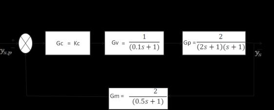
5 7 Applying Ziegler Nichols method : Table (3): Ziegler Nichols adjustable controller parameters for additives loop for Root Locus (sec) (sec) Kc Type of controller 1.01 3.275 0.909 0.491 1.965 1.212
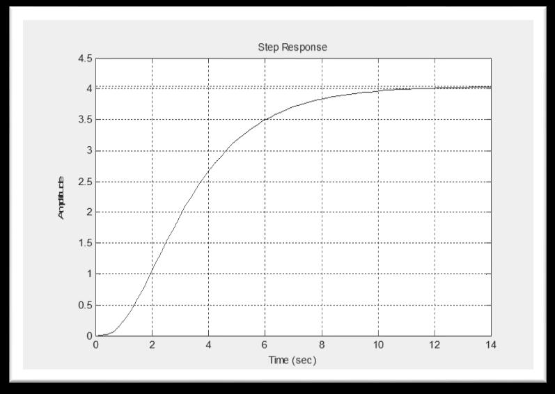
5 8 Offset investigation: ( ) ( ) ( ) 21 ( )( )( ) Kc=1.01fromtuning, ( ) Where: ( ) 24 Magnitude of unit step change =1 = ( ) * ( ( ) ( )( )( )( ) )+ ε
5 9 Response of the step disturbance
Using MATLAB Program: Thisismadeuponastepchangeinsetpointusingthetransferfunctionoftheadditivesloop ( )( )( )( ) =
28
International Research Journal of Engineering and Technology (IRJET) e-ISSN: 2395-0056
Volume: 09 Issue: 06 | June 2022 www.irjet.net p-ISSN: 2395-0072
International Research Journal of Engineering and Technology (IRJET) e-ISSN: 2395-0056 Volume: 09 Issue: 06 | June 2022 www.irjet.net p-ISSN: 2395-0072
1.835
International Research Journal of Engineering and Technology (IRJET) e-ISSN: 2395-0056
5-13 Response of the step disturbance:
Using MATLAB Program
Thisismadeuponastepchangeinsetpointusingthetransferfunctionoftheadditivesloop. ( )( )( )( ) Fig. (7) Step response of P control by Bode adjustable parameter
Table (4.6) Comparing between the adjust parameter using different method of tuning 6 Tuning of loop2 Secondary Loop: ( ) ( ) =Gp ( )
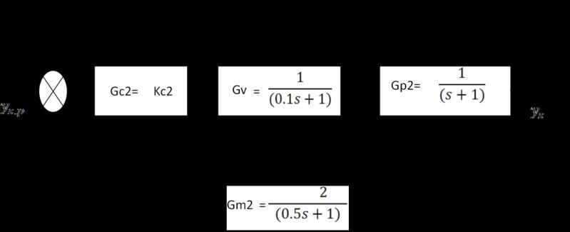
Volume: 09 Issue: 06 | June 2022 www.irjet.net p-ISSN: 2395-0072 © 2022, IRJET | Impact Factor value: 7.529 | ISO 9001:2008 Certified Journal
Fig. (8) Block diagram of secondary loop
International Research Journal of Engineering and Technology (IRJET) e-ISSN: 2395-0056
Volume: 09 Issue: 06 | June 2022 www.irjet.net p-ISSN: 2395-0072
6-1 Appling Ziegler-Nichols method:
Table (5) Ziegler Nichols adjustable controller parameters for loop2 for Root Locus (sec) (sec) Kc Typeofcontroller 22.35 1.43 20.12 0.21 1.965 26.82
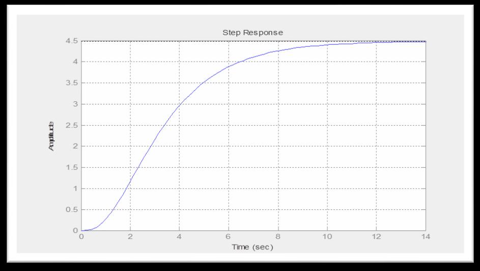
6 2 Response of the step disturbance: Using MATLAB Program: Thisismadeuponastepchangeinsetpointusingthetransferfunctionofthesecondaryloop. =22.40 ( )( )( )
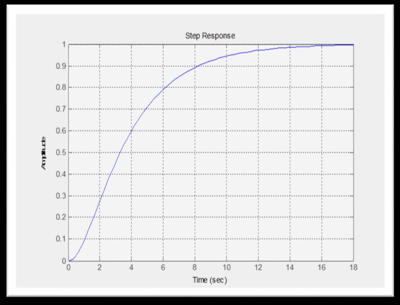
Fig (9) Step response P Bode adjustable parameter
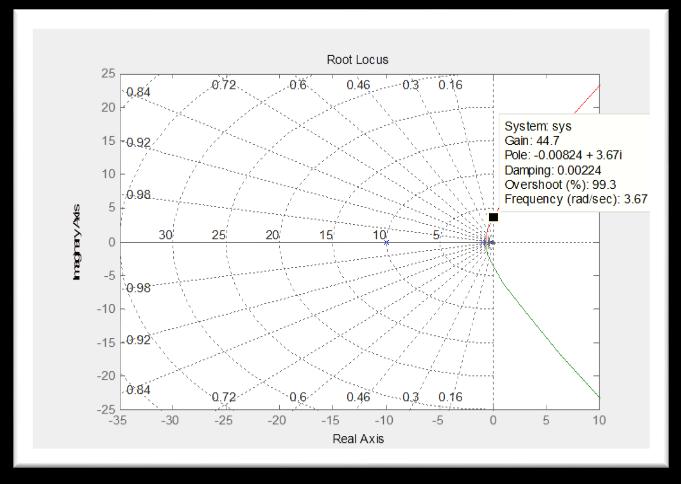
6 3 Root locus method: ( )( )( ) 48
International Research Journal of Engineering and Technology (IRJET) e-ISSN: 2395-0056
Volume: 09 Issue: 06 | June 2022 www.irjet.net p-ISSN: 2395-0072
Fig. (10) Root Locus
Table (6): Comparing between the adjust parameter using different method of tuning
Direct substitution method Parameter 22.40 22.35 22.73 1.71 1.71 1.70
Bodeplot method Root locus method
7 Response of the step disturbance of loop3 :
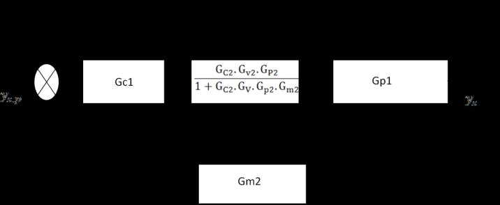
Using MATLAB Program: 1 ( ) ( )
Fig. (10) Reduce cascade block diagram
International Research Journal of Engineering and Technology (IRJET) e-ISSN: 2395-0056
Volume: 09 Issue: 06 | June 2022 www.irjet.net p-ISSN: 2395-0072
( )( )( )
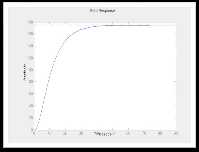
Fig. (11) Response of loop3
The control strategy was developed to control the temperature inside the pipeline cascaded with the viscosity at downstream point of measuring the viscosity which is transmitted to the master controller that reported to the SCADA systemandadjustthesetpointoftheslavecontrollerasthecasemayrequire.Ontheotherhandtheviscositydepressant rate was controlled by single loop flow controller .This controller will reported to the SCADA which in turn adjusts the manipulatedvariablesothatthecontrollervariabletracksthedesiredvalue.
TheauthorswouldliketoacknowledgesupportofCollegeofGraduateandKhartoumRefineryparticularly.
1 Shreve,R.N.andBrink,J.A.,1977,‛chemicalprocessIndustries,4th ed.,NewYorkMcGraw hillBook.CO.
2 Gurash.A.Gasmelseed,ATEXTBOOKOFENGINEERINGPROCESSCONTROL,2014.
3 Dale,E,Edger,T.F.andDuncan,A.M.(2011).,ProcessDynamicandControl,JohnWilyandSons,NewYork.
4 StephanopoulosGourge,2005‛ChemicalProcessControl‛,IndiaPrenticeHall,pp248 257.
5 StephanopoulosGourge,2005‛ChemicalProcessControl‛,IndiaPrenticeHall,pp248 257.
6 Ramirez,W.F,1997,‛CoputationMethodsForProcessSimulation,(SecondEdition),BostonButterWorth.