International Research Journal of Engineering and Technology (IRJET) e ISSN: 2395 0056

Volume: 09 Issue: 05 | May 2022 www.irjet.net p ISSN: 2395 0072
International Research Journal of Engineering and Technology (IRJET) e ISSN: 2395 0056
Volume: 09 Issue: 05 | May 2022 www.irjet.net p ISSN: 2395 0072
Thirumoorthi P1 , Andrew Jebraj Godson A2 , Arun Prasath S3, Mohan Kumar S4
1,2,3,4 Department of Electrical and Electronics Engineering, Kumaraguru College of Technology [autonomous], Coimbatore, India ***
Abstract There has been a rise in renewable energy demands and windmills are commonly used. Production costs have fallen, but operating and maintenance costs haven't. It's difficult to operate and maintain windmills in remote areas with human intervention every day, as humans are susceptible to making mistakes.[2] Designing a data acquisition system based on the Internet of Things can collect data and monitor windmills from anywhere, alerting the individual if necessary. The analog data is converted into digital data by sensors and is fed to an Arduino controller. Depending on the data the controller responds to, the live data from the sensors are visualized directly on a dashboard for remote monitoring. Users can monitor live energy, voltage, current, and other measurements for every windmill on their dashboard. There are several measurements that are monitored, which can be visualized for each windmill.
Key Words: Arduino UNO, Voltage sensor, Current Sensor, Temperature Sensor, GSM Module, Data Acquisition, IOT.
[1]Withtheincreasingdemandforrenewableenergysources and falling construction costs, studies show that the wear and tear on the structures begin to increase substantially, quicklyleadingtoanoverallreductioninproductionbutan increaseinOperatingandMaintenancecosts.[3] Tocombat this, owners and operators can deploy SCADA systems to detectfaultsbeforethereisanysecondarydamage.Through this early detection, repair costs can be reduced, representingsignificantsavings.
Windmillsareusuallylocatedinremoteareas.Continuous monitoring of these windmills in these remote areas requiresalotofhumaneffortifitismonitoredbyhumans. Ashumansarepronetomakingmistakes,electronicdevices such as sensors and microcontrollers can be entrusted to collectdataandhelpinmonitoringtheequipmentfromany locationandtakenecessaryactionsaccordingly.
ThisprojectdealswithdevelopingaDataAcquisitionwhich records various parameters in a windmill that should be monitoredinorder tomaintaintheoptimum operation of theWindmill.
Exposing owners to the true operations and maintenance costs of wind farms and component failures are driving excessivemaintenancecosts.[1] Tocombatthis,ownersand operators can use SCADA (Supervisory Control and Data Acquisition) systems to detect faults before they cause secondarydamage.Byidentifyingthereasonforafaultcan reduce the repair costs, which would result in significant savings.Hence,theaimofthispaperistodevelopaprototype ofamonitoringsystemforwindmillsplacedinremoteareas andtoensureefficientworkingregularlyandfordatalogging, whichiscostefficientanduserfriendly.
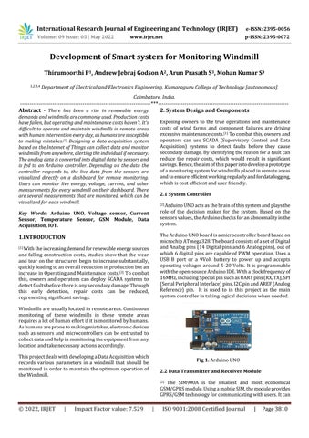
[2]ArduinoUNOactsasthebrainofthissystemandplaysthe role of the decision maker for the system. Based on the sensorsvalues,theArduinochecksforanabnormalityinthe system.
TheArduinoUNOboardisamicrocontrollerboardbasedon microchipATmega328.TheboardconsistsofasetofDigital andAnalogpins(14Digitalpinsand6Analogpins),outof which6digitalpinsarecapableofPWMoperation.Usesa USB B port or a 9Volt battery to power up and accepts operating voltages around 5 20 Volts. It is programmable withtheopen sourceArduinoIDE.Withaclockfrequencyof 16MHz,includingSpecialpinsuchasUARTpins(RX,TX),SPI (SerialPeripheralInterface)pins,I2CpinandAREF(Analog Reference) pin. It is used to in this project as the main systemcontrollerintakinglogicaldecisionswhenneeded.
2.2
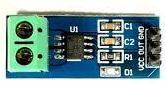
[2] The SIM900A is the smallest and most economical GSM/GPRSmodule.UsingamobileSIM,themoduleprovides GPRS/GSMtechnologyforcommunicatingwithusers.Itcan
International Research Journal of Engineering and Technology (IRJET) e ISSN: 2395 0056
Volume: 09 Issue: 05 | May 2022 www.irjet.net p ISSN: 2395 0072
transmitandreceivemobilecallsandmessagesona900and 1800MHzfrequencyband.Ithasacommandmodeandadata mode. Every country has its own GPRS/GSM and protocol/frequencysetups.Developersmaychangedefault settingsincommandmodetomeettheirownrequirements. WithaPowerInputof(3.4 4.5)V,TransmittingPowerrange of2V,DatatransferLink(Downloadspeedof85.6kbpsand uploadspeedof42.8kpbs).IthasanAntennaSupport,Audio Input/Outputports,serialport(I2CandUART).
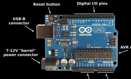
The ACS712 is a hall effect based linear current detector integrated with 2.1kVRMS voltage isolation and a low resistancecurrentconductor.Ithasanoutputsensitivityof (66 185mV/A),80KHzbandwidth,Low noiseanalogsignal path, almost zero magnetichysteresis, stable output offset voltageand1.2mΩinternalconductorresistance.
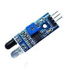
AnInfraredsensorisa radiation sensorcomponentwhich can detect radiations in infrared wavelength range. It comprisesanemitter,whichisbasicallyjustanIRLED,anda detectorwhichissimplyanIRphotodiode.Whentheemitted IR light falls on the photodiode, the resistances and the outputvoltageschangeinproportiontothemagnitudeofthe IRlightreceived.Ithasanoperatingvoltageof5VDC,witha range of 20cm, the range of sensing is adjustable. It has a potentiometerwhichcanbeadjustedtovarythemeasuring range of the IR sensor. In this paper, we’ll be using the IR sensor along with a metal piece to measure the rotational speedoftheWindmillBlades.
Fig 5. IRSensor
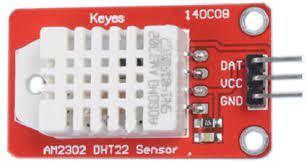
[2] The DHT22 is a digital output relative moisture and temperaturesensor.Ithasacalibratedoutputdigitalsignal.It hasacapacitivemoisturesensorandathermistor.Thereis also a very basic chip inside that does an analog to digital conversion and sends out a digital signal with the temperatureandhumidity.Amicrocontrollercaneasilyread thedigitalsignal.Itoperatesat(3 5)V,hasanaccuracyof2 5%for(0 100%)humidityreading,anda±0.5°Caccuracyfor ( 40to80°C)temperature,noover0.5Hzsamplingrate.
Proteus8Professionalisaproprietarysoftwaretoolsuite designedmainlyforelectronicdesignautomation. Wecan useitforSchematicCapture,simulations,PCBlayoutdesign, microcontrollersimulationsand3Dverifications.
ArduinoIDE(IntegratedDevelopmentEnvironment)isan open sourceelectronicprototypingsoftwarethatfunctions fromCandC++.Itisusedtowriteanduploadprogramsto Arduinocompatibleboardsorotherdevelopmentboards.
International Research Journal of Engineering and Technology (IRJET) e ISSN: 2395 0056
Volume: 09 Issue: 05 | May 2022 www.irjet.net p ISSN: 2395 0072
i. To get the generated voltage we use the voltage dividertechnique.
ii. A30kohmand7.5kohmresistorsareusedtofind thegeneratedvoltageandisconnectedtoA0pinof theArduino.
iii. TheACS712Currentsensingmodulehas8pins.Pin 1,2and3,4areshortedrespectively.Thismoduleis poweredbytheArduinowith5Vatpin8(Vcc).Pin 7(Vout) is connected to Arduino pin A5 and pin 5(Gnd)isconnectedtotheground.
iv. Aload(lamp)isconnectedinseriestothecurrent sensorpins(1/2)andpins(3/4)areconnectedwith thecommonground.
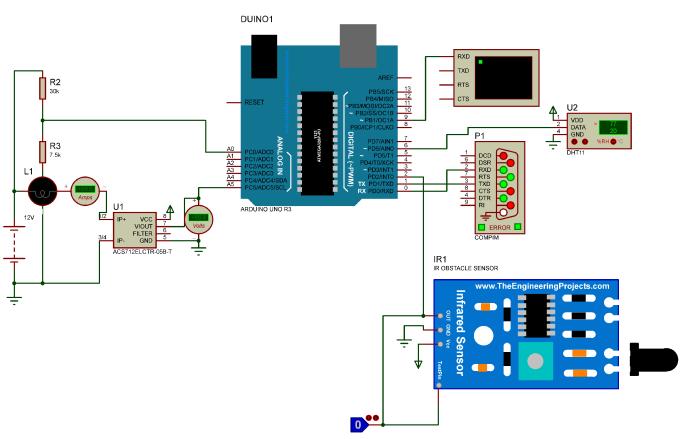
v. TheSpeedmeasuringmoduleispoweredwith5V and the signal pin is connected to Arduino digital pin(2).
vi. The humidity and temperature module is also powered by the Arduino and the data pin is connectedwithArduinopin(6).
vii. Tx and Rx pins are connected to the virtual data transfermoduleandpin(9)ofArduinoisconnected to a virtual terminal to visualize the data in the virtualsimulator.
Start Read Sensor values
Checking for faults (if values exceed limits)
User Alert Notifications
User Information dashboard End
i. Data acquisition: Translation of the physical phenomenonintoananalogmeasurement,whichis thenconvertedintodigitalformat.
ii. Data processing: conversion of the digitized measurements into meaningful indications of componenthealth.
iii. Detection:Classificationoftheconditionindicators as“normal”or“abnormal”.
iv. Diagnosis:Validationofthefaultanddetermination ofitslocationandseverity.
v. Prognosis: Estimation of how much longer the faulted component will last before it needs to be replaced.
vi. Transmission: Transmitting Data to the user dashboardusinglowlatencyprotocol.
vii. Recommendation: Determination of what maintenanceactionisnecessaryandwhenitshould beperformed.
International Research Journal of Engineering and Technology (IRJET) e ISSN: 2395 0056
Volume: 09 Issue: 05 | May 2022 www.irjet.net p ISSN: 2395 0072
ThisprojectshowsthedesignofaworkingmodelWindmill MonitoringSystem:
DifferentSensorsareusedtorecordandconverttheanalog signalsoftheenvironmentintodigitalsignals.Herewehave used DHT22 sensor to measure the heat levels at the oil tanks, gearbox and brakes. A Hall effect sensor is used to record the speed. The ACS712 is used to read the current beingsuppliedbythegenerator.Thevoltagedividerisused toreadthegeneratedvoltage.Thedataistransmittedtothe Arduino.
TheArduinocomparesthevalueswiththepresetvaluesand checksforerrors,ifany;itnotifiestheownerorusereither through SMS or app notification. The voltage, current and othervaluesaredisplayedintheuserdashboard,whichis transmittedwiththehelpoftheGSMmodule.Theowneror manager can view the data with the help of the mobile or webapplication.
This helps record and analyze the data with no human intervention, needing to check and monitor the windmill regularly.
ADCShuntGeneratorWindmillwasusedinplaceofanAC Alternator Windmill. Which gave an output of 25V, which wasusedtochargeLead Acidbatterieswithinthebuilding. TheParameterssuchasVoltage,Current,Power,Speedetc, wererecordedwithahelpofaDataAcquisitionsystemand transmittedwiththehelpofGSMModule.
TheWindmillisautomaticallyturnedaccordingtotheWind directiontousethewindenergyefficientlywiththehelpofa mechanicalyawwhichisfittedattherearofthewindmill.A brake system is used in maintaining the windmill in standstillpositionwhenpowerproductionisnotneeded.
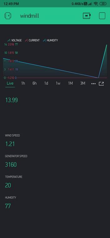
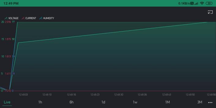
Fig 8. AndroidAppInterface
Fig 8.1 DashboardOutput
i. TheSimulationoftheWindmillMonitoringSystem model has been designed and tested. The DAS or SCADA system can be used to efficiently monitor and maintain the performance and operating characteristicsofnotjustanindividualwindmillbut alsoawholewindmillfarm.
ii. If any parameter is not within the set limit the systemwillalerttheuseraccordingly.
iii. AImethodscanbeinstalledtoallowself repairand self control, enhancing performance and maintenance.
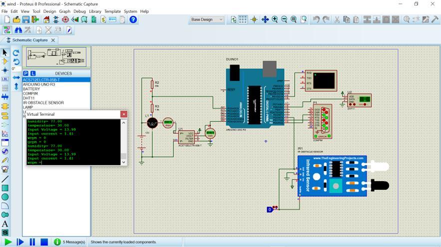
Fig 7. SimulationOutput.
International Research Journal of Engineering and Technology (IRJET) e ISSN: 2395 0056
iv. Due to cost constraints, only few important parameters are being monitored. If cost wasn’t a constrain the more sensors can be used to read moreanalogvaluesofthesystem.
[1] P.AshwiniandR.Umamaherwari,"Wirelesssensor networkforconditionmonitoringofremotewind mill",2017InternationalConferenceonInnovations in Green Energy and Healthcare Technologies (IGEHT).
[2] Zeashan Hameed Khan; Jean Marc Thiriet; Denis Genon Catalot,“WirelessNetworkArchitecturefor Diagnosis andMonitoringApplications.",20096th IEEE Consumer Communications and Networking Conference.
[3] NedelchoNedelchev,DimitrinaKoeva"Automated SystemforControl,MonitoringandDiagnosticsof Windmill.”
Componentsmodel:
i. SystemController ArduinoUNO
ii. DataTransmittermodule GSM(SIM900A)
iii. CurrentSensingModule ACS712
iv. HumiditysensingModule DHT22
v. SpeedDetector IRsensor
Volume: 09 Issue: 05 | May 2022 www.irjet.net p ISSN: 2395 0072 © 2022, IRJET | Impact Factor value: 7.529 | ISO 9001:2008 Certified Journal